Transcription
Design and Verification of Mixed-SignalASICs Using MATLAB and SimulinkAniruddha DayaluPrincipal Application Engineer –Analog/Mixed-Signal Design 2015 The MathWorks, Inc.1
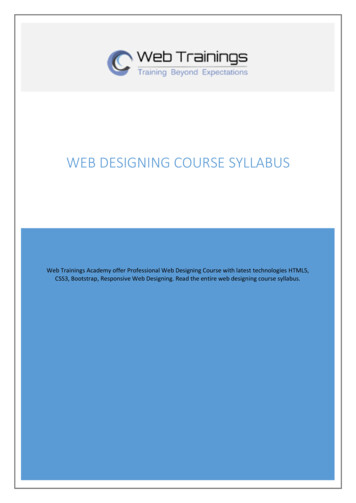
Agenda System Level Design of Analog and Mixed-Signal Components Linking Behavioral to Circuit design and Verifying AMS designs Post-processing of simulation results Conclusion2
Challenges in ASIC Design WorkflowSPECIFICATIONSpecificationisolated fromverificationLimited wareDigitalAnalogC/C HDLSPICEINTEGRATIONSlow areTEST & VERIFICATIONDesign tradeoffs isconnectedteams3
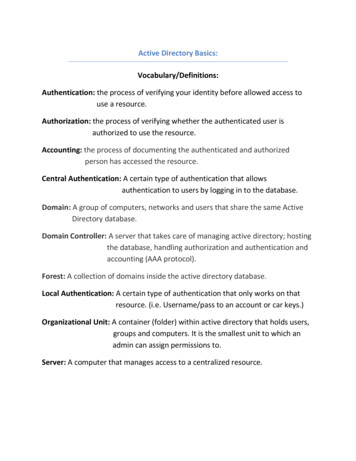
Shifting-LeftWhere Errors are Introduced and Detected55%60%60%50%Shift-left elling & SimulationTestClive Maxfield and Kuhoo Goyal“EDA: Where Electronics Begins”Traditional Verification4
Why Model-Based Design: Achieving the Shift-LeftReduce overall development time All studies point to benefits of top-down designShorter design iteration cycle by 80%Improved product qualityCustomer Study: Benefit of MBD elopment timeEE Times - Top-down verification guidesmixed-signal designsK. Kundert and H. Chang, Partners,Designer's Guide Consulting“Top-Down Mixed-Signal DesignIn order to address these challenges, manydesign teams are either looking to, or elsehave already implemented, a top-downdesign methodology. In a top-down approach,the architecture of the chip is defined as ablock diagram and simulated and optimizedusing a system simulator such as MATLABor Simulink. From the high-level simulation,requirements for the individual circuit blocksare derived.”5
Customer Successes - AllegroAllegro designs ASIC using Simulink: Interpolation engines Digital filters Signal Processing Algorithms Digital PLL’s Digital Sigma Delta DAC’s MATLAB EXPO Link6
Analog Devices – Builds Simulink Behavioral ation-models/mathworks-behavioral-models.html7
Multi-Domain Modeling: AD9361 Agile RF rammablegain tableTunableRF receiverCW, LTE orcustom test signalThird orderDelta-Sigma ADCAnalog continuous-timeprogrammable filtersMulti-rate finite-precisionprogrammable decimation filters 8
Agenda Current Trends in Semiconductor Design and Verification Linking Behavioral to Circuit design and Verifying AMS designs Post-processing of simulation results Conclusion9
Modeling Mixed-Signal Systems in Simulink: Example gnal/index.htmlHow much time does it take to build such a Simulink model?10
Mixed-Signal Systems Require Different Modeling ApproachesAlgorithmsBehavioral ModelsAnalog CircuitsControl Logic11
Simulink is the Platform for Mixed-Signal System DesignMATLAB & C Code IntegrationSimscape Electrical and Physical ModelingBlock LibrariesStateflow12
Fast Simulation and Large Scale Modeling with SimulinkContinuous and discrete time simulation Multi-rate schedulers and ODE solvers Multi-core parallel simulations Solver profiler and acceleratorScale up adoption across large organizations Variants and model management Build libraries of components Model encryption OrderOrderIII Switched Capacitor Order II13
Start with Designing and Implementing Digital Filters Realize model with basic Simulink blocksExport coefficients to MATLABCreate multi-rate filtersGenerate synthesizable HDL code14
Agenda Current Trends in Semiconductor Design and Verification System Level Design of Analog and Mixed-Signal Components Post-processing of simulation results Conclusion15
Linking System-Level Algorithms and Circuit-Level ImplementationLinking MathWorks and EDA tools: Suitable for analog, digital or mixed-signal systems Target system-level and circuit-level designersALGORITHMS & ARCHITECTURETEST & VERIFICATIONDesign methodologies are true differentiators: Innovate more rapidly Achieve faster design cycles Introduce fewer errors Understand the system and its implementationREQUIREMENTS &SPECIFICATIONSAlgorithms & Control ION & INTEGRATIONHardwareSoftwareFirmwareMCUDSPVHDL, VerilogFPGAASICSpice-likePCBASIC16
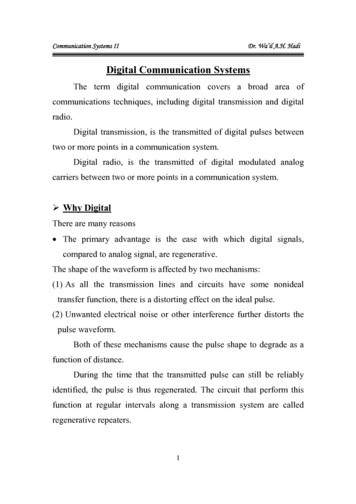
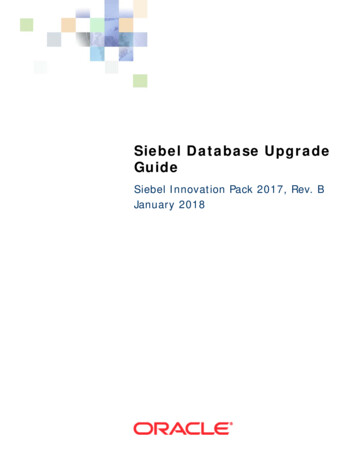
EDA Workflow Integration: Co-simulationAlgorithm DevelopmentSystem Design & Architecture RTL Co-SimulationCadence IncisiveMentor Graphics QuestaADMSSynopsys VCS RTLSimulatorFPGAIn-the-LoopAnalog Co-SimulationCadence VirtuosoCadence PspiceSPICESimulatorImplementation and IntegrationEDA Flow (Digital, Analog, Software)Product17
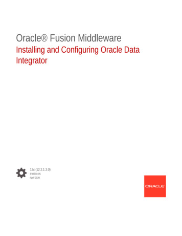
EDA Workflow Integration: Model ExportAlgorithm DevelopmentSystem Design & ArchitectureRTLVHDL, VerilogC/C SystemCTLM 2.0SystemVerilogDPI-CImplementation and IntegrationEDA Flow (Digital, Analog, Software)Product18
Two Complementary Verification ApproachesAnalog / Digital co-simulation Test your IP within the context of a full system simulation Use the visualization and analysis capabilities of Simulink and MATLAB Test each module independently of other modules Validate the IP behavioral model and speed up system-level simulationSystemVerilog (DPI-C) code generation Fast simulation using the native SystemVerilog API HDL simulator independent Real number models for analog and digital IPs Most suitable for testbench generation and IC verification (regression tests)19
Agenda Current Trends in Semiconductor Design and Verification System Level Design of Analog and Mixed-Signal Components Linking Behavioral to Circuit design and Verifying AMS designs Conclusion20
Post-Processing of Simulation Results with MATLAB Analyze all kinds of simulation results in MATLABImport files from Spectre, HSPICE, Eldo, Questa ADMS, etcFunctions, Measurements, and VisualizationSignal Processing, Statistical analysis, Model fitting,RF Analysis, Sensitivity Analysis, Monte Carlo, Cadence Virtuoso,Spectre, Pspice Synopsys VCS,HSPICE, Mentor Graphics QuestaADMS,Eldo, QuestaSim, 21
Cadence MathWorks Integration for Advanced Data Analytics Cadence ADE XL interface to MATLAB in latest MMSIM– Enables Simulation data to be seamlessly transferred into MATLAB Environment– Leverage MATLAB advanced data analysis capabilities to post-process and verifysimulation resultsCadence Virtuoso ADE-XL– Cadence Newsroom Link22
Agenda Current Trends in Semiconductor Design and Verification System Level Design of Analog and Mixed-Signal Components Linking Behavioral to Circuit design and Verifying AMS designs Post-processing of simulation data23
Design and Verification of Mixed-Signal Systems with MathWorks Use many trusted functions for algorithmic design You don’t have to be a modeling guru Anticipate implementation impairments in Simulink Iterate more rapidly in a truly mixed-signal simulation environment Build and reuse system-verification test-benches through your development process Reduce the verification effort Use MATLAB for the analysis and visualization of your circuit simulation results Automate the large scale analysis of data and gain deeper insights24
Call to Action – MathWorks Resources Semiconductor solutionsUser storiesTechnical SemiconductorDevelopsDesignsand ifies3G SemiconductorMixed-Signal40TimeGbpsby 50%and Leadin inTwoNew-GenerationMonths “Circuit-levelHDA vironmentVerilog-Ahelpedsimulationustheybreakfor issueweto ntmillionstheexplorationSimulinktasksof Usingand letsMATLABto ransientsimulationverysimilarensureseffects.timeto �theup positiononlywith ultimatelytoolinfasta FujitsuToyocomSemiconductorLaboratories ofCorporationAmerica25
Call to Action – Download Mixed Signal Example gnal/index.html Shorten your learning curve starting with validated examples, tutorials, best practices– Most popular mixed-signal examples for ADC, PLL, SerDes, and SMPS– Getting started with Simulink using step-by-step tutorials– Full documentation and latest features26
Call to Action – MATLAB Central File leexchange/ An open exchange for the MATLAB and Simulink user community– Get answers, challenge yourself and others, and share your knowledge– Tap into the knowledge and experience of over 100,000 community members andMathWorks employees.27
Speaker DetailsContact MathWorks IndiaEmail: Aniruddha.Dayalu@mathworks.inProducts/Training Enquiry BoothLinkedIn:Call: dayaluEmail: info@mathworks.inShare your experience with MATLAB & Simulink on Social Media Use #MATLABEXPOI use #MATLAB because Attending #MATLABEXPO Examples I use #MATLAB because it helps me be a data scientist! Attending #MATLABEXPO Learning new capabilities in #MATLAB and #Simulink at #MATLABEXPO.Share your session feedback:Please fill in your feedback for this session in the feedback form28
Allegro designs ASIC using Simulink: . Cadence Incisive Mentor Graphics QuestaADMS Synopsys VCS Algorithm Development System Design & Architecture FPGA In-the-Loop SPICE Simulator RTL Simulator Analog Co-Simulation Cadence Virtuoso Cadence Pspice. 18 Product Implementation and Integration EDA Flow (Digital, Analog, Software) EDA Workflow Integration: Model Export RTL VHDL, Verilog C/C .