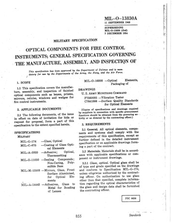
Transcription
Eii.Fili: lfi::Fi,MIL O-I3B3OAiili11 SEPIEIfBEA 1963'['t-,jiTiffffiå.i,F,t:.7 DECEMBER 1951i,;MILITARY SPECIFICATIONFOR FIRE ICATIONGOYERT',{INGA}{D NSPECTIQNOFASSEMBLY,TTM MANUF'ACTURE,This qecif.cotionÐelcuc end' b nølllta b¿at e1qrottcd by tha Department-ofend' th¿ ai¡ Fotcc'thcNo,tv'armv'tluoft "-là;im t",,;;;;i;*;;';t'MIL-O-168981. SCOPE1.1 This specifrcation covers the manufacture, assembly, and inspection of frnishedopticel components such as lenses, prisms't ri.rotr, reticle-s, windows and wedges forfire control instruments.2. APPLICABIEDOCUMENTS'2.1 The following documents, of the issuein effect on date of invitstion for bid's or.qo"åt for proposal, form a part qf this.specificetion to the extent specified Glassi OPticel-Coating of Glass OPtical omPounds;Non-Curing, PolYsulfide Base-Mirrors,Glass, FrontSurface Aluminized,OPtical Eìeforments-Adhesives,. Glass toMetal for Bondingof Lenses-OPtic¿lElements'Packaging ofDRA*INGSU. S.A¡uY Muxnroxs Coxu-rxPF?660086 -Vibration TesterQuality StendardsC?641866 -surfacefor OPtical Elenents(Copies of apeciñcetion¡ end drawingr requi'redby aupplierr in connection with ryeciflc procurer¡cntluncti,ons ghould b obt¡ined from tùe pro'cori¡rg ¡c- "tivity or ss dircct d by the contracting o4*t')3. REQIIIREMENTS3.1 Genenl AJI optical eleurents, components and systetts sh¿ll comply wit'Ìr therequirements of ,this specification, except asfurther defrned in the detailed instrumentspeciñcationor on applicable drawings fonning a part of the contract.3.2 Materiats. ]fateriats shall b i¡ accordsnce with applicable specifications or component or instrument drawing-s.3.2.1 Gløss, optical. Optical glass shall beof type and grade specified on the drawingsand conform to Specification MIL-G-174'unless othçrwlse authorized by the contracting officei. On authorization to use giassother ',han that specified, complete information regarding the optical cha¡acteristics ofthe gìass and tiesign data shall be furnishedthe contracting officer., ';.R55Siondords
MII-{FI3B3OA. 3.5.1.1l. rsignallon of delect srze. Limiting slzls uf surf:,ce defects shall be designatrxi oú tha dran'irrgsby two numberswhichrefcr to t',r'r; graded sets of surface qualitystanrla¡dsDrawing C7641866.The first number shall refer to scratches and the secondriumber shall rcfer to digs (see6.3).3.2.2 Ad'he¡¿'le.Unlessspeci!ìcdby the contract or order, optical cemcnt' shall l¡e inaccordance with Specificatior. IvIII-A--392C.3.2.3 Bondíng compound. Bonding compound for glass to met¿l bonding sh'ail b inaccordancewith SpecificationIfII-Ä-14443'.3.2.4 Sealing compønú. Sealing compouadshall be in accordance with SpecificationMII-S-11030.i.ã.2 Scraf¿fus.3.5.2.1 Círculnr el¿mcnt. The combinedìength of meximum size scratcheslocated oneach surface of an optical element sh¿ll notexceerlrine quarter the diameter of that element.3.2.5 Refl'ectbn reduci'ng rtIm. Reflectionreducing fiim required for coating of specifiedoptical surfaces shall be in accordancewithSpecifrcation MII-G6?5.3.2.5.1Reflecting wrf ones.Reflecting surfaces aluminized shall be in accordarrceu'ithSpeciñcationMII-M-13508.3.3 Mechanical d.imensions- Optical elements shall conform to the mechanical dimensions and optical dats specified on thedrawings of in the contract.3.3.1 .Rizr edges.Rim edges of all opticalparts shall have a chamfer of 0.020 inchO.OOS 45o - 15o as messured along the"tunless otherwise specified by theface widthdrawing. Edges rneeting'at angles of 136oand larger need not be beveled unless specified by the drawings.3.4 Finish and defects. Finish and defectsof t1re oplical glas.sshall conJorm with requirenrents of this specificetion or as indicated on applicable drawings or optical diagTsrrur.3.4.1 GI*ss defects. Striae, cords, ream'b'trbbles,seeds,strain, laps, or folds in p¡essings, or alry other defect p'ermitted in Specification If II-G-l?4, locatedin such a point,plane, or position as to impair the perform. ance r¡f the element shall be cause for ¡ejection of that element.3.5 Optical glass surface quality.3.5.1 Opticald'rausings and' di grama. Component optical drawings shall indicate surface quality, and optical system diagramsshall indic¿rtethe diameter of an axial beamof rays.3.5.2,1.1 trfa,rirnun combined' I¿ngths of\lthe¡r a meximum size scratch isscrø¿c/r.c.\'.presettt, th,e sunr c'f the products of thescratr:i¡ nurlrbers times the ratio of theirlength to llrr: dianleter of the elementor apone half thepropriate zone shall not ev-ceedmaximum scratch number. When a maximumsize scratch is not present, the sum of theproducts of the scratch'numbers times the¡atic of their length to the diameter of theelementor appropriate zone.shallnot'exceeilthe maximum scratch number.'9.5.2.2Non¿irntl.o.r shaped e enent- Thecomputing diameter of element shapesotherthan'cjrc:ular shall be that of s circle of equalarca. Scratches beyond the free aperture oflny element as given on the optical systemdrawings t¡r detail dlawings shall ¡ot be considerccirvhen applying the appropriateformuìa specificdin 3.5.2.1.1.3.É.2.2.f True roof surfa'ces on prísms.True roof surfaces on prisms shall be consideretl equivalent to a single surface of an,,equal to the sum of the individual roof areasfor purposes of scratch anrl dig computation,excepbtlrat the roof edge shall not be consideredin the summation of the length of theallorvable scratches. Scratch and dig tolerances for roof prisms are set on the basisthat the equivalent surface above is viewedfrom the air side. (3.?.10.1).3.5.2.2.2 Surfa,ce qttality, centra,l zone.Areas of surfaces whose specified scratchqualities are 20 or better shall have no conglomeration of scratches such that in any2MISCELIANEOUSq{Á
MII,4-T3B:¡OAleugth and the rn¡,ximum width' Bubble ¡izet¡lerances are identical in all respectsto digs;but the identical bubble tolerances, whileidentical, are in addition to the digs-area there are morela-inchdiameler circularfou" separate scratches' This requireít"t""nt ¿o.t nãt appty for scratches sm¿ller10. Smslt reticle surfaces equaltftt""u-Uerto or less than 20rnm (0'?8? inch) diametærshsll be hendled separately on the drawingswith elimination of zones' partícularly forcementedreticles.3.5.2.3 Surfone PnJity, outer zone' Surfaceeleouality outside the free aperture of enyotherå"rrt tn"lt be coruidered 80-50, unlesswise required.3.5.?-4Coøtíng sct øt ches. Coati n g scr atches'glassscratches which do not penetrate the'samelimitstheshall be within"urface,which are specifiedin 3.5.2' Coating sctatchesshall not count in determination of the uormal surface quality but shall be counted inaddition to thã surface quality--ouce to evsluate the glass scratches and one to evsluetethe coating scratches3.5.3 Diss.3.5.3.1 Dig d.csignntroa. Dig numbers arethe actual diameters of defects allowed, apeci- 'fred in units of 1/100mm' In the csse of irregular'shaped digs the diometer shall b trk"" as the average of the maximum Jengthand maximùm width3.5.3.2 Masimun úze d.igs.The permissiblenumber of maximum size dig:s shall be oneper each 20mm of diameter or fraction thereäf orr'ttty single optical surface' The sum ofthe diameters of all digs as estimated by the'inspector shall not exceedtwice the diameterof itre maximum size specified per 20rn'rndiabemeter. Digs less than 2.5 micmns shallignored.3.5.3.3 Surfate quzlíty. Alt diss on eachsurface whose dig quality is number 10 orsmaller shatl be separated edge to edge by atIeast lmm. The me¿surement of scatteringshall not be required for surfaces where digsLargerthan number 10 are allowed'shall, 3.5.4 Bubblesand' ínclusiozrs'Bubblesúe classedas surface digs' Any inclusion inthe glassshall be treated as a bubble' The sizeof irregular shaped inclusions shall be considered as one half the surn of the maximum3.5.4.1 Ms.tim1lm size bubbl.e'*.The permi¡sible number of maximum size bubbles shsllbe one per each 20mm of light path, or fractiou thereof, of any single element.The eumof the diameters of all bubbles as e¡tim¿t¿dby the inspector shall not exceed twice thediameter of the maximum aize specified per20mm diameter for each 20mm of light patù'When surface dig quality is 10 or better, bubbles shall follow requirements for diga asspecifredin 3.5.3.1.3.5.5 Límíting sìze of nt'rføne dcfech' If'not specified on drawings, the limiting sizeof scratches or digs sh-allbe determined fromTable I and is based on the beam diameter ofmagnifrcation.3.5.5.1 Beom dio'm¿tet of møgnífiæfíont'The beam diameter sh,gll be obt¿inecl fromthe opticat date. It is the dis'net r at the surfac of the optic in question, of a bundle ofaxial rays.proceeding to tþe obserrerfs eye'The dianeter of the bundle et the e¡reshell bet¿ken as 3.5mm, (0.13?8 inch) if the exitpupil is over 3.5mm. If the exit pupil issm.sller than 3.5mm, t\at diameter 'of thebundle at the eye shall'be the ss'me 8s theexit pupil.3.5.5.2 Beo't¡t&ze lcssthnnin tã'blgI. Whenthe beam size is less than that specified forfocal planes and ne¿r local planes of any surface, lhe size of defect is determined by themagnification of the eyepieceor of the eye'piecemultiplied by magaification of the erecting system.3.5.5.3 Zone. Tlte surface on which thebeam diameter of an axial bundle is 25 percent or less of the free aperture shall b divided into a central and outer zone. Thecentral zone shaìl be half the free aperture inwidth. Zone sizefor reticles shall be as specifred'in3.7.11.1.3.6 Cement defects-Cæmentbubbles,voids,undissolvedparticles, dry spots, blisters, dirt(lini or dust) within the free aperture of thecemented iens shall not exceedthe limits of.,;.857Slondords
tII.-{Þr38:¡0.LT¡¡uu Ifoçr¡B@Edbsr.rPt¡Ðé ¡¡d uos focd PlucCeot¡ul nmof sülsccX dl¡EÉtdOutcr tonÊDir(ED)504t).404030m'I5IO5ó.specif,ed indefects for dig:s and bubbles3.6.3.1thru 3.5'4'1 inclusive'3.6.1 Surfo,ceqtnlity of cenented,fane'Ceshallinsiae the free aperbure*"î'ã.t*itcementtheth¿ton the basisil;;;ã;ãsurface of the specifiedsingleañ";;;;;when not specified'.the sur i;î;Glitv.shall be interface quality for a cement facefaces'¡"i*een that of adjacent*"ãlit"separation3.6.2 Ed'ge sepørølions' Edge.compoopticalinand edge cement defectschamedgeth-ebeyond.ñ.ff not extendorlens"ï"tcemented surface or t1'9;";';iih;l/z'thedisprism by a distance g¡èater t}raysurfac-e.chamferffiä ;J*een the ceiltttttaradius of the clear'of the component "na ttt"dimension of anyaperture. The maximumdefect shaìl notcdge separation or cementsurface of the comextend into the cemented.15.10l520of 3'?-2- andto meeting the requirements.voids or separal.g.l.6Z, ihere shall be noof the bondedtions that exceed 1ò percentare&,3.? OPtical comPonentaeiaits'g.7.1 Tentpeio'ture operàtion' CeT-"1':UÚ.4'¡ -t"corlrl'u'trr¡Lù as a result:f."*Po:l:"-:: plus,i:"oirporr."t,àr minuì 80o andbient air temperatur,, :--,, -rr it,î äö e. ìrrrlt not develop"f-eatherh*,'. * "7evidenceof separat'ionoi' sotteni5 :i ::-""X'tl- t;l'sPeciñeu;;'ä',i;ï";;;;ìx"ePt asincrease or dewith the provision ttrit tfrecementof edge separation or edge.;;i;;;;;irejection'à;;'.;t shall be causefore op3.7.2 R etøtit'e ht¿midity-temperøt'uras a re sultofcrotiott. Cemented "ompo"enttatmosphqre of plus:;Ë;;"-;- ""tn¡i""tantl.at least 9'çv¡"Y---¡ ' temperatu'e,iäõ;r'ùu rf]::::minimumsubsequentrelative h umidity' and- -- .r- nrofïTìi::iåïJi,F'''n:1ll:1,ì'i;;'¡¡ **::J'#lH;Jå:'::äandPlus160oïil:: äö*t,,,"ïl:'l: ji::äi"n* i,.ijr'fi o-*evidence"iiiï'-ãó'"r.':pij T:.: iedge seParatlonsat the surface cham. than 7/zmm", *""""dshall not exceed10fer of the lens o'-pti"*'percent of the Perimeter'(gtass -to ntetal)'3.6.3 Boæding d'ef ectsa conthalj.haye alongB;á"d optical ""t"*bli"tadhesivetinuous bead of ãã "otn"asurface'of the bondedi'tt""¿g"Subsequent3.6.3.1 V oi'd'sønd' separatiozs'exceptof cement or other defects'"ãit"ningas specifredin 3'6'3.7.3 Reflection r:ed'ucing fiItns'.'Optical"surfaces.;;iñed on drawings as.";i;;.abe coatedwith reflectionäË;;"-tirn*t'reducing film (see 3'2'5)When speÇiñed'3.7.4 Opticot blackenín'g'4xlx
MIL4-I3fËÌO.1,ground surfacesof optical elementsshall beblackened with a finish approved by the responsibletechnicalactivitY.3.7.5 Resoluúioz.Resolution tests shall beperformed on each objective' collective, erector, eyepiece,mirror, vredge,rvindorv,filter,prism and prism assembly(optical) as speciñed in 4.2.5.3.7.6 Ps.rdl¿lism, fi'Iters. Pa¡allelism ofñlters shall be within the tolerance specifiedon the drawings. When no tolerance is specified, filters located internally or in front ofa telescopeshall not exceed 1 minute of arclight deviation. Filters located between theeyeldns and the exit pupil shall have a lightdeviation not exceeding5 minutes of arc.Reticle scale3.7.7 Reticl¿ sco'Ie sprc,.cíng.spacing shall be tested in accordancewith4.2.10.5:3.7.8 Polished surføces. Polished surfacesshall show no evidenceof grayness or stainwhen inspected in accordancewith 4.2.2.3.7.9 Leæes.3.?.9.1 SurÍo¿e q1u.Iity. Surface quality ofeech lens shall be in ¿ccordancewith applic¿ble drawings .or instrument specifications.When not specified,the surface quality shallbe as follows: Objectives, erectors, windowsand other elements which lie at least fifteendiopters out of the focal plane, shall have asurface quality of 80-50 or better. Field andcollective lensesshail have a surface qualiþof 20-5 in the central zone and 40-15 in theouter zone.Center lensesof oculars shall havea sur{ace quality of 40-15 in the central zoneand 40-20 in the outer zone. Eyèlenses,excepting those in symmetrical eyepieces,shallhave a surface quality of 40-20 in the central'Whenthezone and 60-30 in the outer zone.field and eyelens are identical, the surfacequality for both shall be 20-5 in the centralzone and 40-15 in the outer zone. Fii¡erswhich lie betrveenthe eyelens and the exitpgpil shall have a surface quality of 40-20 inthe central zone and 60-30 in the outer zone.Filters which lie internally shall have thesame requirements as specified for prismsin 3.7.10.1.Filters located in front of the ob-jective shall have a surface quality of 80-50or betfer.3.7.9.2 Edge chips. Edge chips which donot encroach on the free aperture of the lensshall be allowable, providing the chip doesnot interfere with the sealing of the lens.inthe mount. The surface.of all chips lsrgerthan l/2mm, as meåsured at the largest extremities, shall be "stoned" to roughen it andIessen the possibility of annoying reflecfionsand additibnal chipping. The sum of thechip widths of chips largel than f/smm, asmeasured at the edgeof the lens, shall not exceed 10 percent of the perimeter. Fracturesin excess of t{2mm depth in any face or edgeshall be ground out.Ground out areas shallreinain within the applicable stoned chipIimits of this paragtaph. Fractu¡es in excessof these limits shall be ceuse for rejection.Stoned chips and fractures in ground faceswhosä total summed up areas are in excessof2 percent of the area of the ground face orwhich are in exóäss of 2mm depth shall because for rejection. Such.stoned .chips andfractures shall be cause fo¡ ¡ejection whenthey interfere with the optical psth otmounting or sealing methods rega¡dless oftheir size.3.?.9.3 Con*entricíúy. Edges of all elementsshatl be trued to diameter about the opticalaxis as a center by g¡inding. Iænses composed of two or more elements shall be cemented and centered in such a manner thatthe axis of each element coincides with theaxiÉ or axes of the othe¡ elementor elements.Ocular lenses shall'be concentric within 6minutes of arc, and all other lensesshall beconcentric within 3 minutes of arc unless'otherwise speciñedôn the drawing or in ôetail specifications. After centering and cèmenting, mechanic¿l eccentric glass overhang in excess of 50 percent diametertolerance shall be removed. Optical eccentricity is.definedas the angular deviation,afterrefraction of an incident ray which is coincident with the geometric axis of the lens.'3.?.10 Prisms and,mirrors.3.7.10.1 Surface qunlity. Surface quality ofeachprism shall be in acco¡dancewith appli-859Siondords
Mtr 13830,A'specifications'csble drswings or instrument15 diopter-sle¿siatlieFlt t*f".es whichbe 80-60 orshallqualitvtft. focal plane,6 to surfacetheiloi'å;; åi tt," focal plane40-15andzoneb" io tot thó centr¿l]iiiliewhichfor the outer zone. For surfacessurfaceplanervithin 6 diopters of the foca!ss fôr reticles'il"tttt shall b the same\¡/)rich dog.7.LO-2Edge chips' Edge ehips-"o.to"chon túe free ape::ture of the,,oiwithin the followingOtit- tfr"fl be allowablechip widths shalltheofsumTheii-it"tio*:length of edgetheofpercent¡rot exceed 10shall l)eChipsoccur'chipsthe""'*iì"ftfrom thã bevelled edge' noì from;*;;;;ãi-e. after bevelliag and not t''e höã;";shaìl not betoi. Ct ips less than þmmthanand not stoned; chips larger""t"t.Ai¿** ehall be stoned. Encroachment of chipson the faces of tue prismíliliñ;;trednominal lengthirãt" ii ¡"velled edges'If the"ore bev,elling)befsharfcoinerì ;ä;Jtowhich is adplismtheofedgeài tft" tit"ttestpolished face is an inch or le-cs';;;toif said"nvchips may encroach the faces 1mm;encroachmaychipsi""gtt'zî"t. *.eds 25'4mmtltathf.i. shall be permiïibt e .providedwithin-rerferewhichlf,"r" are no edge cùipsmetirãas oi sealing and the chipsåi""tì"gaperture'ão oot eicroach upon the freetheoptional su¡faces and shsll be treated in3'7'10'1's¿me maoner as specifiedin3.?.10'5.3 Ape'rture' surlaces' Apertureis.tÐsu¡'facesof prisrns through which tightparttclesl-,e tlaasmitted shall be free fromprocof silver or ¿luminum remaiuing fromessing'rf other surfaces'3.?.f1 Reticles-qual3.i.1l.i S'utface qun'Lity'The surfacedrawing:s'ity shail be as specilìed on the'Whenqualityuot so speciûed the surfacespeciliedfor focsl pianesin 3'6'6'3';ilil útfot zone sizes' The centrsl zone shallaperture'"-".pibe the central area, one half the freegraduaii v¡idth, f¿r reti-cleshaving reticlethoseandtion extrerrities within this area'linesvertical,-tìll.t having irorizont¿l andRetia¡ea'ìuiurru, gratluatic''¡s outside thecent¡allt*uiirg gracluatic¡nsoutside thethewidth'"tu,áråt, o.t" i,"U ttt. free aperture-inthreearea'shall be the central;.;;L-ï;"tcaperture in width' Imperfec'freethefourthsperLtvo"a the free aperture shall beli;"notdoÁìil"¿ providing their characteristicsimpair performance of the iustrumentchip limitatious3.?.11.2 Edge- cit'ips'rvith 3'7'9'2'"aS-ein uccordancerh;ii t o"v"luÁtudParal3.?.11.3 Parallelism of flnt zurfcces'withinbereticle flat surfaces shalll.fittìfdrawings'the tclerances specifred by theth'e drawing'Wfr"r. no tolerance is given ondeviaTheshall be 6 minutes of ¿rc devia3.?.10.3Drwwing requirent'et¡ts';;;l;i"t;"ceerrorortion of angle errors, pyramidal errortion of light .?.11-4 Ma¡kittgs' Reticle markingsspecifiedasbeshalltilt,].*lu[iorr, and imagêlnroogtt an eyepieceof essentiallv¡"îi.ï"¿¡eticle willon the drawings.the game pov¡er ttnder which theLettersprismsùe-vio*"¿-in the finished instrumen!'3.?.10.4 Erecting prßms' Erecting,orpar{nu¡nberin4'2'5'2'(rvhetherintrr¿ oo*"ralsinspectedãsspecified"h;ii;;to graduations) shall be inspectedãã¡."tor3.?.10.5 Reflecting surfores-si'l'ueredpti* tify foi legibility' Defects in.lumbersprovided eachaluminized.ãi r.ti"tt shalt úe acceptableSbenpartially sili"tt.l o. ngure is legible eshallshallprismsnumberscil type letters andvered surfaces of ocularwidth of theirregufromfreedomshowshall itiã.'1i"" breaks one half theandarp.tcontaina magline shall be permitted' For reticlesiarities when inspectedwith the aid oflines orper5ofbreak1eyepieceing *o. than rS lines,riifrer of at least the porver of thelinespertains'thereof shail Le permitted'.All;;;.ti""if,e instrument to luhith the prismandwidthuniformshall appear to be ofapshalllines3.?.10.5.2Defects. Defects on reflectingofti u intersections;õlion othe¡defectsassamethesppear"-oãsurfacesr ¡r.-Él ñltrfìllqBóO
ìrIMIL r38:lOÀSurface of collectivelensesin efocal plane( b ) i-ess criticsl surfeces,Surfac of ocuLerfreld lenr nearest the retide,Collective len¡, center len¡ orprism eurfacæ nesr a focalplane( c ) Least critical surfaces,Âll other surfaces of windowa,. objectives,Primu, erector,andeyeleruesvaria-'D ar to be sharp. Smooth or abruptshalllineentirethealongwidlhãi"* i" linelinethepercentof20ofiot ¡" in excesswithb shalllinesbowediiatn. In addition,casnin dimensional requirements snd in noofexcessin 'sh.all reticle lines be bowedtheatfiIletradiusthe reticle line width- Theof reticle lines shsll not exceediot"*."tio"forthe line width. Acid burns shall be c¿useviewedigrej"ctioo, if visible wheu reticlêwith approPriate eYePiece'3.?.11.5 IlJumínatedrethhs' If the brightness of a defect is greater than the brighto"s" of a reticle line whcn illuminated by theassociatedinstrument light or light of equalintensity, the defect shall be cause for rejection.3.7.12'Wed.ge ønd wind'ou. IVedge endwindow surface quality shall be in accordance with 3.?.9.1.3.8 Optical sYstems.3.8.1 t/zr¿sseÍLble¿I.Opticalsystems of specified design procured unassembled shaÌl bethesrouped into systems in accordance withãpücal diagram pertaining to the system, andsheil b inspected as specified in 4'2'9.3.8.2 AsseÍLbl¿d. Optical systems of specified design procured assembled in their rs'spective instruments shall be assembled inaccordance with the drawing and specification for the instrument, and shall be inspectedas specifiedin 42.10.3.8.2.1 Def ect críteria. Defects not otherwise covered in this specifrcation,which willnot impair the performance of the finishedinstrument, shali be permissible.'Whether aparticular defect shall be permitted will depend on the location of the element in the finished optical system' Defects in elements notnear a focal plane are not as important as inelemenls which lie in or near a focal plane.ln all inst¿nces primary emphasis shall bepiaced on the performance of the lerrs orprism rather than its appearanceunless thelatter definiteiy indicates poor workmanship.The order of importance is as follows:(a) Most critical surfaces,Etched surface of reticle3.8:2.2 Alin¿n'ent. The optical elements ofall optical systems procured aseembled intheir instruments shall be alin d so th'et theexit pupil viewed on the optical a: is Éh'allhave a minor diamet¿r not less fhnn 0 per-cent of its m ajor diameter. The exit pupilshall be concentric with the exit free aperturewithin 10 percent of the exit free aperturewhen viewed from a point on the optical axirat s distance of approxim"telY two feet fromthe eyeleus.'Whenrpecified, moir3¡8J.3 SeÃl¿diohts.ture preventive sealing compound (ee 32.4)shall be evenly applied to the opticsl component to form an unbroken bead. When injection sealing is utilized, 2l hours shall elapsebefore collimstion of the i¡strunent.3.8.2.4 Pold.íng. The use of pads, shims,wedges, or opening under or around opticalelements is prohibited and shgü b esu¡¿ forrejection of the instrument unless specifledby the drawings.3.8.2.5 P erf ormønce clwronterriatins-''3.8.2.5.1 Vibrøtion.,{fter being aubjectÆdto the vibratioh test specifiedin d2-10.7 theoptical instrument shsll show no dirt (dustoi lint) in excess of thet allowed by the de'tail specification. In the sbsenc of det¿ili{uirements, dirt in any confined space shallttot U. in size or amounts larger than the allowablê dig specificetion for the adjacentsurface requiring the best dig qualify. Theinstrument shall show no evidencæof looseordamaged parts subsequent to this test.3.82.5.2 Slnck. All complet¿d subass"mblies in which an optical elementis physicallyBó1StondordsiiI
MII, I383OAasupported f¡om a'nother part or parts bythetosubjectedbeshallbondgiiJ,t t" metalshock test.3.8.2.5.3Cl¿ønlines¡.r'he optical surface ofandcompleted instruments shatl be cleanfree of condensatesand volatile substancesexamined by method specified in'*tr.tbei.i.to.g. Dust retention grease shall nottheuséd except with specifrcauthorization ofresponsibletechnical activitY'3.8.2.5.4PoraJh.z. Parallax shall l;c t'emoved where sPccifredin 4'2'10'1'3.8.2.5.5Fhed eyepiecef octts'Unless otherwi'se specified the reticle at the center ofthe field itt"ll b" in sharp focus whcn the eyepiece is set between minus 0'7Í¡ and minusi.O diopter. A calibrated dioptometer rvith amagnidcation of at ieast 3 po\¡/er or an equivatent auxiliary telescope shall be ' used tomake this setting.3.9 Workmanship. Standards of work¡ranship shall be such that components *'ill meetall iequirements of this specificationand anyreferenced specificationsor drarviugs wheninspectedin accolcìancervith section4'the general specifrcationshall apply. Appropriate sam¡ìing proceduresmay be usedwithprior approv¿l of the responsibletechnical""i;Ï,ùitchoniu.I dùnensí.otts.Eachoptical coinponent shali be checkedfor compliance rr.'tbhthe meciralricaldimensionsqf theclr:r*'ing and sltall be inspectedin accordance.¡¡ith thã r,-'t¡ttiremrtntsand tests in thi's speciÍicatirin.t:e qttnlity. Each element shaìl4.2,? .{:¿,'i'nby the foìlowing methods forbe mpliance3.7.r 0.Ì.4.2.2.1 Ins¡tc':tícn netlt'od,No. J' The elèment to be il;¡recteo shall be vierved againstâ t{roì.it1,.i.¡la,il úr opaì surface illuminat'edfrurn i,eni:tii irl' a forty watt lamp approxirnatelr; lì illches from the glass' Two or moreopa{¡re irctrizotrtalbars occupying approxirnatåly lr2 thc area of the glass shall be placediti front of rrnd in contact with the glass'4.2.2.2 Ins:pcctionmetl¿odN,. P' The lightthrough grortnd glass fi'om a 40 watt bulbshall be passedthrough the element'Defectsare ctrservedl¡y light scatteredfrom the sul'face r','hile vielvinç¡ it at ap¡:r'oxirn':rtely90'4. QUÄLITY ÄSSURANCE T'ITOVISIONS. i.o the path of the ì.rea¡nagaiust a dark back4.1 Responsibitity for inspection' ise't.Z.'JT en.lt erøtu'rc test.chase order, the supplíer is t'esponsihleforthe performance of atl inspection require4.2.3.1Tl'n'ee out of the lirst i0 of s*"n[,type of centerttedor br¡ncìedhisutilizema¡'supplierthebe testetl atshallspecified,rviseptãt.C uudet e¿icl.cont:.'tctlabot'4tot'ycommercinloranyou'n facilitiesthe high nud lorv temperatutes .?.1. H there is l'easouto cloubtquality, litcofanypelfolmtotlteright*.nt ,.".vesto tes¿actditionalsâmplesasright is the insþectionsthe insl¡ecttlr deems lleces'sal'y'u'here such ins¡tectionsare cleemednecessat'J' subjectàd to thesetests shail have passeclallto assure supplies and selvices confot'm toother t'eqttiredtests.prescribed lequirements.4.2.3.2The cemented or bonded compo4.2 Test methods.nents shall be subjected bo an ambient temperature of minus 80o F. for 5 l"r-rurs'lVhenOpJ.Z.L Inspcctíon, oTttículco'ntponeæfs'inspecfeclvisually at this ttìmperature, andtical componentsshall be inspected by apagain after remaining frve hout's.¿t- roomproved optical metliods and equipment inthe optical assemblyshall showàccorrlancewith applicable detail specifica- temperature,or reticulationtions. In absenceof approved test methods rro evidence of "feathering"of the conrseparationnobethereshallandofand equipment, the following proceduresIMISCELI.ANEOUS862
t,FI':DfII-{Þr38:XtAponents. In performing this test the opticalessembliesshall not be subjected to any undue thermal shocks while being cooléd tominus 80o F., or while being warmed to roomtemperature.4.2.3,3 The cenrentedoptical assemblllshallthen be subjectedto the following test at thehigh temperature. One of the componentsshall b held rigidly in such a manner thatthe cement¿d interface shall be approximately in a vertical plane. A weight of suchmagnitude as to induce in the optical assembly a unit shear stress of 5 ouncesper squareinch of area of the cementedor bond'edsurface shall be suspendedfrom the other component. ln no case shall the weight be lessthan one ounce.For lensesthis area may bet¿ken ¿s the projected areâ, rr X whet'eD is the diameter of the lens in inches. Theentire apparatus shall be allowed to soak atan ambient tempet'ature of plus 160" F., or'slighily higher, for 2 hours. The lens'shallpass the requirementsspecifiedby 4.2.6 whentested at ¡oom temperature and the ¡nove. ment or slippage of one component with respect to the other shall not exceed.002 inch.In performing this test the optical assembliesshall not be subjected to any undue thermalshockswhile being raised to 160o F. or whilebeing c.:oledto room temperature. '1.2.3.4Failure of oneopticalassemblyshallbe causefor stopping shipmentspending aninvestigation of the çause. The contractot'shall institute an immediateinvestigatidn irrthe presence'ofa representativeof the con,tracting officer if the representativedesiresto be present to determinethe causeof failure. If the investigation disclosesa fault incementing ot' bonding, acceptanceof opticalassembliesincorporating this fault shall bestopped pending correction. The contractor'shall correct his cementing technique anCshall correct all faulty optical assembliespreand shipmentsviously produced.Acceptanccwill be resumedrvhenten corrsecutiveopticalassdmbliesof the type rejected have successfully passedthe temperaturetests.4.2.4 Tenperaturerelatiz-ehunirlity.4.2.4.1 Three out of the ñrst 10 of eachtypeof cemented or bonded components st thebeginning of each contract, or upon change inmethod of cemeting or change in type ce'ment, shall be tested at the temperaturehumidity conditions specifiedherein. If theleis reason to doubt quality, the right'is reserved to test additional samples as the inspector deemsnecessary.4.2.4.2 The cementedor bondedcomp
axial rays.proceeding to tþe obserrerfs eye' The dianeter of the bundle et the e¡re shell be t¿ken as 3.5mm, (0.13?8 inch) if the exit pupil is over 3.5mm. If the exit pupil is sm.sller than 3.5mm, t\at diameter 'of the bundle at the eye shall'be the ss'me 8s the exit pupil. 3.5.5.2 Beo't¡t &ze lcss thnnin tã'blg I. When
