Transcription
Tutorial II: Cadence VirtuosoECE6133: Physical Design Automation of VLSI SystemsGeorgia Institute of TechnologyProf. Sung Kyu LimLast Updated: 2/7/2022I. Setup for Cadence Virtuoso1. Copy the following files into your working directorycds.libdisplay.drflib.defs.cdsinit (Make sure that the file name is ".cdsinit". If you copy this file from awindows machine, the file name will be "cdsinit".)calibreDRC.rulmyDesign.tar.gzYou will also need the “test.gds2” file you generated during Innovus lab.2. Type the following commands to source the designated filessource /tools/software/cadence/ic/cshrc.latestsource /tools/mentor/calibre/aoi2019/meta137.cshrc3. Open cds.lib and replace 'your working directory' by your working directory as follows. Typethe FULL directory name. You can get it by cd in 'your working directory' and typing pwdin the console. Leave “myDesign” untouched at the end.DEFINE myDesign /your working directory/myDesign4. Open lib.defs and replace 'your working directory' by your working directory as follows. Sameas above: type the FULL directory name. Leave “myDesign” untouched at the end.DEFINE myDesign /your working directory/myDesign5. Uncompress myDesign.tar.gz in your working directory.tar -xzf myDesign.tar.gz6. Run Cadence Virtuoso by typing 'virtuoso'. Make sure to run the command in the same directoryas of the .cdsinit file.
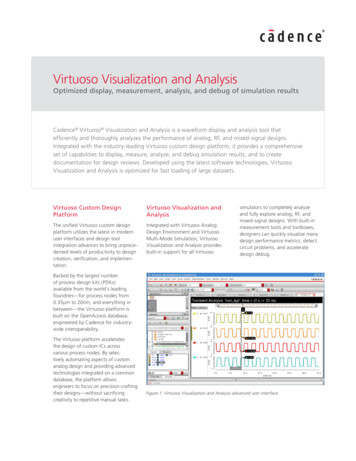
II. Generation of Final LayoutsAfter you have typed ‘virtuoso’, the Virtuoso window will appear as follows.a. Choose 'File' - 'Import' - 'Stream.', then 'Virtuoso(R) XStream In' window will appear asfollows.2. Change the file type to “All Files(*)” and choose GDS2 file in ‘Stream File’ (test.gds2 fromInnovus lab)3. Choose myDesign in ‘Library’4. The top cell is “test” by virtuoso (this is the name we specified in Innovus when savingtest.gds2)5. The window should look as followsa.
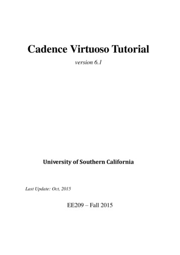
6. Click 'Translate'. There must not be any error during translation. If you meet warningmessages, you can just click ‘No’. (you should have only 1 warning, no error)7. Choose ‘Tools’ - ‘Library Manager ’ in Virtuoso main window which will open the LibraryManager window as follows.8. Choose ‘myDesign’ in Library column.9. Choose your design in Cell column (“test”)10. Double-click ‘layout’ in View column.11. You may get messages regarding the unavailability of license. Just click on “Session” every time.
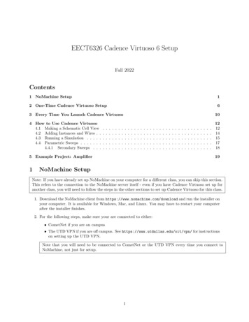
12. Then a layout window will appear. Maximize and zoom-to-fit (by pressing ‘f’ on keyboard) toget a better clarity.13. The current window shows standard cells and routed metals but you cannot see the details ofstandard cells. These abstract cells are called standard cell instances. To get a final layout, weneed to load standard cells and replace standard cell instances by standard cell layouts. This iscalled 'flattening'.a. To do this, choose ‘Edit’ - ‘Select’ - ‘Select All’b. Then choose ‘Edit’ - ‘Hierarchy’ - ‘Flatten ’ and click ‘OK’ in ‘Flatten’ windowwith the default settings. Clicking the empty space in design will cancel the selection.14. Choose 'File' - 'Save' to save your flattened design.15. Compare this layout with your encounter layout. Do those look similar?
16. To Capture Screenshots: Choose 'File' - 'Export Image.' in the layout editor. Supportedformats are bmp, jpg, png, and so on.17. How to View Specific Metal Layers and Via:a. On the left of your screen, there is ‘Layers’ tab. In here you can control visibility of eachlayers.i. If you click 'NV', only the selected layer will be shownii. If you click 'AV', all layers will be showniii. Check the ‘Used’ box in the Layers section to only show the important layers andvias. Then uncheck or check the corresponding visibility box ‘V’ to un-toggle ortoggle the visibility of a given layer.
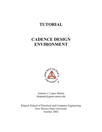
iv. After you toggle visibilities, you can re-draw the layout to apply the changedvisibilities. (Choose 'View' - 'Redraw', or click 'Zoom to Fit' button in thetoolbar)v. Choose 'Tools' - 'Display Resource Manager' in the main Virtuoso window.When 'Display Resource Tool Box’ appears, click Edit, and Display ResourceEditor window appears. Choose any metal layer, change 'Fill Color' and 'OutlineColor', and click 'Apply'. Redraw the layout to see if the new color was appliedwell.
b. Here is the metal layer mapping. You will need this in 'Lab Problem: Generation of finallayouts and DRC' section.i. L49 - metal 1ii. L51 - metal 2iii. L62 - metal 3iv. L31 - metal 4v. L33 - metal 5vi. L37 - metal 6vii. L39 - metal 7viii. L41 - metal 8ix. L43 - metal 9x. L45 - metal 10c. Actually each metal layer has two different names. For example, metal 1 layer hastwo names - 'metal 1' and 'L49'III. Design Rule Checking (DRC)
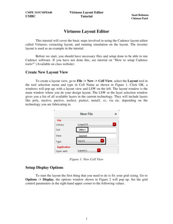
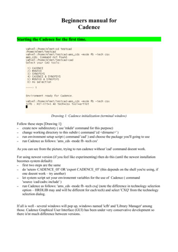
1. After flattening, choose 'Calibre' - 'Run nmDRC'. Click 'Cancel' in 'Load Runset File' window.The caliber window would then appear (there might be some defaults filled in)2. For the DRC rules file, select the button with three dots ( ) and then select the calibreDRC.rulfile. Just check if the “Rules” button on the left turns green. The final window would be likethis:
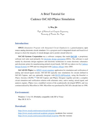
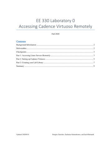
3. DRC Run Directory should already be auto-filled with your current directory. You can leavethis as it is. If this is empty, enter your current full directory path in this box4. Click ‘Inputs’ tab. The window would be auto-filled as follows:5. Run DRC by clicking 'Run DRC' button6. When DRC is finished, look at the following window to check the number of DRC violations
7. A check box will be red if it has any DRC violation.8. Summary of DRC would be stored in *.drc.results and *.drc.summary in your working directory.
v. Choose 'Tools' - 'Display Resource Manager' in the main Virtuoso window. When 'Display Resource Tool Box' appears, click Edit, and Display Resource Editor window appears. Choose any metal layer, change 'Fill Color' and 'Outline Color', and click 'Apply'. Redraw the layout to see if the new color was applied well.