Transcription
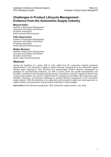
11th SA INCOSE ConferencePretoria, 16-18 September 2015Product Lifecycle Management: The Salvation of Systems EngineeringNathan W. HartmanComputer Graphics TechnologyCollege of TechnologyPurdue Universitynhartman@purdue.eduC. Robert KenleyIndustrial EngineeringCollege of EngineeringPurdue Universitykenley@purdue.eduCopyright 2015 by Nathan W. Hartman and C. Robert Kenley. Published and used by INCOSE with permission.The Devil is in the details, but so is salvation.― Admiral Hyman G. RickoverAbstract. Many of the challenges faced by the systems engineering communityarticulated in Systems Engineering Vision 2025 relate to detail-oriented activitiesthat typically occur during the design, integration, assembly, and test of systems.With advances in computational capabilities, virtual system prototypes are availablethat use highly detailed representations of a system’s components and provide ameans for performing the virtual integration, assembly, and test of systems and forcomposing custom designs of systems and systems of systems. This paper describeshow linking systems engineering with product lifecycle management provides ameans to address these systems engineering challenges. This linkage will allowsystems engineers to increase the actual and perceived value that they are deliveringto the system’s stakeholders and provide systems engineers a pathway to moremeaningful and relevant participation throughout the system’s lifecycle.1. IntroductionSystems engineers are masters of the abstract; product designers are masters of thetangible.Systems EngineersProduct DesignersMasters of the abstractMasters of the tangibleFigure 1. Two Engineering Tribes1
The desire of the systems engineer is to ensure the pieces of a system work together toachieve the objectives of the whole of the system. The strength of systems engineers is theirability to articulate the objectives of the system and the operational sequences of the systemfrom a functional point of view. This approach uses many abstract representations that arepurposefully distinct from the representation of tangible system that executes these sequencesin the real world to achieve the system’s objectives. (Wymore, 1993, 7-8) describes severalbenefits of dealing in abstractions summarized in Table 1. The “avoids” statements are meansthat are more relevant to the masters of the abstract for achieving their end, which is toprovide functionality to the user. The “provides” statements are means that are more relevantto the masters of the tangible for achieving their end, which is to define concrete solutions.The desire of the product designer is to specify an artefact that satisfies the objectives andassociated constraints (Visser 2004). The strength of designers is their ability to producetangible artifacts that can be used to manufacture and assemble products that can be offeredfor sale.Table 1. Benefits of Using AbstractionsAvoids Confusing ends (what the userwants) with means (what theengineer designs)Stating the problem in terms of apreconceived set of solutionsConfusing system-wide functionalfigures of merit such as reliabilitywith: its estimate based on a design its estimate based onobservations ormeasurements of a specificsystem under specificconditionsProvides Insight through considering multiplesolutions that may be: Practical solutions Idealized solutions Do-nothing (status quo)solutions Otherwise bizarre solutionsContext for evaluating andcomparing solutions2. The Challenges Faced by the Masters of AbstractionA World in Motion: Systems Engineering Vision 2025 (INCOSE 2014) presents thechallenges of a systems engineering community that seeks to ensure the pieces of systemswork together to achieve the objectives of the whole of the system. As examples of currentpractice that touches on product lifecycle management, the vision describes three specificapplications in industry:1. The virtual rollout of the Boeing 787 Dreamliner that virtually created parts, andintegrated and assembled the virtual system using visualization and simulation.2. Model-based systems engineering at Ford Motor Company that manages designcomplexity for onboard electrical and software systems by applying multiplemodeling technologies including UML, SysML, and Simulink that are integratedusing an underlying system for configuration management and product datamanagement (CM/PDM).3. Allowing customers to compose custom designs of Scania trucks by providingclients the ability to select the cab, engine, chassis, engine, transmission, andaccessories. The details of components such as engine cylinders, push rods, and2
combustion chambers are specified to increase their interchangeability and to reducethe number of variations of components that must be manufactured and stocked.In these three examples and others, it was not necessarily the case that systems engineerswere the perceived or actual agents who drove these changes in business processes. Instead,changes like these are in response to the availability of technologies such as ever-increasingcomputational power, immersive technologies for data visualization, 3D printing (also knownas additive manufacturing), advances in materials science, and the emergence of the internetof things. In addition, the globally connected IT environment that permits geographicallydiverse collaboration throughout the supply chain and with multiple stakeholders whiledesigning products and after products are placed into service. These advances appear to beoutpacing the advances in methods and tools used by systems engineers that allow them tocontribute their wisdom and ability to apply abstractions to these situations to deliverinnovative system solutions that keep pace with technology changes and still enable systemsengineers to continue their role of ensuring product quality and safety up front.Model-based systems engineering (MBSE) is the formalized application of modeling tosupport system requirements, design, analysis, verification and validation activities beginningin the conceptual design phase and continuing throughout development and later life cyclephases (INCOSE 2007). The current focus of MBSE is on tools and methods that capturedocument-based representations of requirements and functionality in descriptive models thatcan be analyzed for completeness and consistency within the scope of systems engineeringand that have the potential to be converted to executable models that generate quantitativeinformation for evaluating system behavior.The link between the abstractions used in formal systems modeling for specifying,analyzing, designing, and verifying systems and the knowledge representations used formodels used in design engineering, manufacturing, operations, maintenance, and repair isquite weak and must be strengthened to provide a model-centric approach that integratestechnical, programmatic, and business realities. Model-based approaches that strengthen thislink will enable systems engineers to apply their patterns of thinking and navigate amongrelated viewpoints to understand the complex behavior of a product and the entire enterprisesystem that interacts with the product throughout its life cycle.Systems Engineering Vision 2025 describes a scenario of model-based systemsengineering being the “norm” for systems engineering execution with system models thathave both “black box” views based on functional abstractions and “white box” views thatincorporate geometric, production and operational views. In this scenario, these models willbe linked to 3D printing to produce physical prototypes to increase the ability to investigatetradeoff between form, fit and function.3. The State of the Art and Practice of the Masters of the TangibleProduct lifecycle management has many contemporary definitions (Grieves 2005; Grieves2011, Stark 2011, CIMdata 2015), which tend to include the following commoncharacteristics:1. Product lifecycle management is generally viewed as a strategic method forconducting business within the extended product ecosystem – not just design andproduction within a company, but it also accounts for supply chain, sustainment, andmaintenance among many other phases of the product lifecycle.3
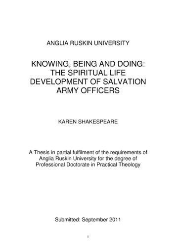
2. Product lifecycle management is an environment, a way of working. It is a system ofmethods, processes, and practices enabled by modern information technologies. It isnot simply a collection of tools.3. The human aspects of interpreting information, using tools, and enacting strategicdecisions cannot be discounted. Given the highly configurable nature of toolsets tomatch corporate processes, the information author/consumer metaphor for articulatinghow product data moves through an organization accounts for the various human rolesin designing, producing and sustaining a product.4. The concept of product lifecycle management covers the entire product lifecycle,from requirements definition to product disposal. While early incarnations of productlifecycle management were very tool-centric and primarily addressed managing CADfiles, modern product lifecycle management systems are actually a collection of toolsdeployed in different ways to move product data through the various groups in anenterprise and to give life to that product data over a span of decades.“Product Lifecycle Management is the product viewpoint of the whole business. It iseverything that improves the development and management of products from an enterpriseand lifecycle perspective . Without products, we have nothing to sell, and therefore have nobusiness” (PLM Interest Group 2010, 486). The current focus of product lifecyclemanagement is on tools and methods that capture document-based representations of physicalitems in digital product models that can be converted to instructions for manufacturing andassembling products.In summary, product lifecycle management is an environment in which informationtechnology tools and processes allow a company increased access to product definition datato better develop, manage, and support their products. It is a collection of interconnectedtechnologies that enable companies to make better business decisions throughout the lifecycleof a product by leveraging the intelligence embedded in digital product definitions. Productlifecycle management defines and controls data collection processes, integration,transformation, analysis and visualization processes; from establishing a product'srequirements, to the design, manufacturing, maintenance and recycling of the product. Figure2 illustrates a conceptual depiction of product lifecycle management, with a key elementbeing the business-oriented themes, which require various levels of product and processrepresentations at multiple levels of sophistication to serve the authors and consumers ofproduct information across the lifecycle.4
Figure 2: Conceptual model of product lifecycle management4. Connecting the Masters of Their Domains: A Path to SalvationAdmiral Hyman Rickover, who led the US nuclear navy for over three decades, comparedsystems engineers and their modes of operating to a mythical character and described the wayout of being caught up in a mode that only deals in abstractions.In Greek mythology, Antaeus was a giant who was strong as long as he had contactwith the earth. When he was lifted from the earth he lost strength. So it is withengineers. They must not become isolated from the real world The Devil is in thedetails, but so is salvation. (Theodore 1995, 195)When designing and producing products, humans use various forms of representations todepict the nature of the product at any given time within the lifecycle (Buciarelli 1994,Hartman 2004, Hartman, 2005, Henderson 1999; Collins 1987, Keller and Keller 1996).Historically, artists, scientists, inventors, and others have used drawings made in many levelsof detail to depict their ideas. These drawings would use different styles of projection andartistic rendering to describe the shape, function, and behavior of a product. During the stageswhere systems engineers define requirements or when conceptual designers select materials,product representations are rather abstract as described previously. However, the realm of theproduct designer often in concrete details expressed by mission parameters or functionalrequirements, finished machining processes and tolerances, or manufacturability orsupportability concerns. In contemporary design and production environments, designers arecreating digital representations to describe their products to both humans and machines atvarious stages of the lifecycle. While those representations were often done as 2D drawingsin the past, modern design environments yield 3D models as a design artifact. Companies arenow leveraging the embedded intellectual property, the communicative power, and theinvestment of time in the creation of the 3D models during the development stages of thelifecycle by using their derivatives to drive downstream process. Therein lies one of theprimary differences between product lifecycle management and systems engineering.Systems engineering uses various abstractions of a product and its elemental components to5
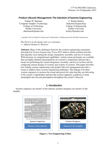
define a system in terms of its required input, outputs, and functions, and its components; topredict future performance of the built product; and to measure value to clarify the trade-offswithin and between the choices for requirements and components (Buede 2009, 131). Productlifecycle management uses representations that are more detailed as a mechanism forcommunication to support manufacturing, operations, and product sustainment. Figure 2shows an adaptation from Grieves (2011) of what is becoming known in the product lifecyclemanagement community as a model-based definition (MBD).Currently, much of the focus around the concept and creation of a MBD is targeted atreplacing traditional 2D drawings (Figure 3). Instead of using orthographic projection withassociated dimensions, tolerances, and annotations, model-based definitions use CAD modelswith associated annotations and symbols to define the shape of the product. However, even incurrent practice, little if any attention is given to the behavior and context elements of amodel-based definition. Model-based definitions are often used primarily as a proxy fordrawings in defining what a finished object should look like and how to inspect it to see if ithas been made correctly. The shape definition elements of a model-based definition includeitems such as geometry, dimensional and geometric constraints, or tolerancing information,but are often sterile, lacking explicit information that can be used further on in the productlifecycle. The behavioral elements of an MBD include material models, machining processmodels, additive manufacturing material and process models, supply chain capability andcapacity. The contextual elements of a model-based definition include in-situ data regardingoperating performance, production factory performance, user/operator conditions. However,these capabilities do not exist in what is often a monolithic representation within modernCAD tools, and therein lies the crux of current discussion – how do we link product lifecyclemanagement and systems engineering? One of the keys to doing this is to be able to includethe behavioral and contextual elements of a ‘model’ and their relationship to the systemsdepicted in a typical systems engineering ‘model’.Figure 3: The evolution of the model-based definition in PLM and SEThe evolution of many products from purely mechanical, to electromechanical, tosoftware-driven electromechanical has required a level of preliminary analysis and prediction6
not seen in previous decades. SE tools are typically good at the latter items, while productlifecycle management tools are not, and vice versa. Understanding how these elements of aproduct will interact, and how one manages the development/production/support data fromthese elements, are vexing issues. As the nature of product design and production haveevolved due to the proliferation of digital tools and data, the nature of product definitioninformation has evolved as well. Table 2 provides a brief comparison of systems engineeringand product lifecycle management along several contemporary factors which influence thedevelopment of complex products.Table 2. Comparison of SE and PLM on Issues of Product ComplexitySystems EngineeringProduct Lifecycle ManagementLevel of RepresentationAbstractInformation TypeModels that depictsubsystem interactionValidation to stakeholderrequirementsAbstract models andschematics to depictperformanceEarlyConcreteModels that capture geometric,dimensional, and behavioralconstraintsPhysical production matchesvirtual definitionInterconnected design, supplychain, and sustainment usingdigital product modelLaterSystems engineersValidation that the systemfunctions correctlyEveryone elseValidation that the componentsare made correctlyProcessInfrastructureLifecycle StageOrganizational RoleRegulatory ComplianceSystems engineers use models to define system functionality, define the options for thephysical components of the system (in this instance, hardware and software are treated asphysical components, allocate functionality to physical components, model system dynamicsand execution, and predict system performance and resource utilization, as shown in Figure 4.The operational concept and functional architecture are abstract entities according to Lewis(1986), who stated, “abstract entities have no spatiotemporal location; they do not enter intocausal interaction; they are never indiscernible one from another.” The physical architectureand allocated architecture are abstract also, as they are models of the actual physical entitiesthat comprise the system. MBSE information is actionable in the sense that the descriptionsof desired behavior, structure, requirements are adequate for designers to take action.Snelders and Schoormans (2004) discuss how this notion of actionability for products ofsystems engineering is optimistic at best:The actionability of product attributes is defined in purely pragmatic terms, with afocus on new product development: ‘‘By ‘actionable’ we mean that the attributesindicate specific actions the manufacturer must take to build such a product’’(Shocker & Srinivasan, 1974, p. 922). At the same time, Shocker and Srinivasan areoptimistic, in that even ‘‘vague attributes (such as ‘sportiness’) may still provesufficiently actionable for the framework to provide guidance to manufacturers’’In addition an optimistic interpretation of the actionability of systems engineering products,the descriptive models produced using MBSE are not used by designers and are not even7
used by systems engineers who perform system validation tasks using system simulations.The information produced by MBSE models is not executable and is linked with simulationtools in an ad hoc manner, if at all.Figure 4: Current State of MBSE and System Simulation (adapted from Levis andWagenhals. (2000))Modern product lifecycle management tools struggle in defining, managing, andpropagating many items that are quite apparent in the top-down Vee-model representation ofthe project lifecycle (Figure 5). The following list are common items that are often confusedby the differences between different functional groups in an organization and their mandate(design/optimize vs. design/make): Requirements analysis and requirements managementDescription of the functions and modeling of the system architectureBreaking down the functions for distribution among the individual specialist designdisciplinesSynchronization of component design and developmentSimulation of all parts of the systemValidation of subsystems and components against requirementsThe Vee-Model is used routinely in the aerospace community, as well as other areas whereproduct complexity is high, to show the interaction between the lifecycle phases, and theverification/validation loop between requirements and production.The abstract world of SE and the tangible world of PLM do not share a common authoringenvironment for product definition, and they do not share a common language or ontology fordefining the elements of those products either. As such, authors and consumers of productdefinition cannot move information fluidly between the levels of product abstraction goingdown and coming up the Vee8
Figure 5: Vee-Model for the Product Lifecycle (from Hartman, Rosche, and Fischer(2012))As indicated in the three examples of the virtual rollout of the Boeing 787 Dreamliner,model-based systems engineering at Ford Motor Company, and customers composing customdesigns of Scania trucks, systems engineers were not the perceived or actual agents forintroducing these processes. All three examples are located in the Vee-Model at the bottomand along right-hand side of the Vee-Model. Herein lies a key source of the current conditionof systems engineering and its need for salvation.The systems engineers who are engaged early in the lifecycle drive paperwork down theleft-hand side of the Vee and develop initial verification and validation plans; however, theyare rarely engaged in a meaningful way in the final planning or the execution of theintegration and test activities coming up the right-hand side of the Vee. If we carefullyinspect the Vee-Model in Figure 5, we see that during verification, the testers “feed the beast”in the systems engineering department with reports, as indicated by the arrow labeled“Verification and Validation,” but that useful initial inputs and feedback from systemsengineering that would be indicated by arrows from left to right are missing. It is very likelythat testers perceive systems engineers to be mere clerks who check the box that the testershave turned in the required reports that systems engineers specified when coming down theleft-hand side of the Vee. In addition, the models and rationale that systems engineers usedearlier to define requirements and test cases may not be available to the integration and testteam or, if they are available, in a form that is useful to them. Having completed theirrequired reports, the integration and test team moves on to solve the day-to-day problems thatthey face in assembling a product that works and is acceptable to stakeholders.Figure 6 represents the version of what should be occurring coming up the right-hand sideof the Vee during verification and validation. Ideally, systems engineers would engage withdesigners, integrators, assemblers, and testers interactively and dynamically to ensure that theproduct is built right and the right product is built. The product lifecycle managementenvironment should allow for the capture and representation of knowledge that systemsengineers develop coming down the left-hand side of the Vee and provide efficient andmeaningful approaches to updating this knowledge based on the details that are discoveredduring verification and validation. The outcome of the effort will support updating thesystems engineering models to predict the test results more accurately. Instead of being clerks9
who check the box as reports are turned in, systems engineers can engage their intellectualabilities in solving the concrete, yet complex problems that occur in the integration and testphase of activity. This combination of model-based systems engineering and productlifecycle management can ultimately lead to an outcome described by Buede (2009, 359), butrarely implemented in practice: “As confidence in a specific model increases, the model canbe used to replace some of the instrumented tests and demonstrations.” However, a keyenabler to this scenario is a model-based product definition that includes not only shape, butbehavior and context elements as well.Figure 6: Verification, Validation, and Acceptance [from (Buede 2009)]Integrating MSBSE tools into the PLM environment can also support designers as well.The benefit of integrating product lifecycle management and systems engineering applies tothe top-down, requirements-driven environments that gave rise to the Vee model, which arebecoming rare as the operational environment of system is changing more rapidly andrequirements cannot remain static for long. It also applies to environments where customerscompose made-to-order system designs or where owners of different systems decide tocompose a system of systems from existing systems to achieve previously unanticipatedobjectives. The systems engineering models used coming down the left-hand side of the Veegenerally are not developed with the benefit of detailed knowledge of actual design solutions.The product lifecycle management environment is able to provide a medium ofcommunication (i.e., a tangible model-based definition with behavioral and contextualelements contained) that allows the composers of these new creations that use existing designsolutions and systems engineers to have meaningful interactions. In addition, big-dataanalytics can be used on information captured in PLM to generate suggestions for existingdesign solutions to meet current requirements. From these interactions will come anunderstanding of the impacts of the compositional choices on performance, interfaces, andthe value delivered, which will increase confidence that the composition will function rightly10
and perform the right functions. During the integration and test phase coming up the righthand side of the Vee, access to MBSE models and simulations will assist designers indiscovering and validating proposed design changes to mitigate failures or shortfalls thatwere discovered during testing.Within a typical product data environment, the definition of the elements of a productoften use abstractions that are able to provide the behavioral and contextual elements of themodel-based definition that is emerging as the conduit for communication within the productlifecycle management environment. The communication inputs and outputs of the variousactors in the product lifecycle require a very flexible, yet robust digital product representationthat can be translated and disseminated with high degrees of fidelity to the original definition.While many commercial software vendors, standards developers, and advocacy bodies lobbyfor one CAD-derivative format over another, there exists a framework for selectingappropriate derivative data formats (Hartman, Rosche, and Fischer 2012). The frameworkdoes account for the notion of translation between various product data authoring andconsuming software tools. Yet, it does not address translation at an operational level nor doesit propose solutions for addressing the inevitable translation, validation, and curationchallenges that arise when trying to move semantically rich product data from one tool toanother. The use of ontologies to manage this process seems promising (McKenzie-VealHartman, and Springer 2010; Chaparala, Hartman, and Springer 2012); however, they tend toonly accommodate the shape definition elements contained in CAD and CAD-derivative datatoday. If ontologies are to be useful in helping bridge the gap between systems engineeringand product lifecycle management, they must also capture behavioral and contextualinformation with high degrees of fidelity. We must also be able to articulate system-levelontologies, such as “airplane” or “automobile,” that are able to characterize the actions of theentire system. Sub-level ontologies would then be applied, such as “engine” or “controls,”with each successive layer of product (system) complexity broken down into its constituentelements. Finally, the identification and mapping of the larger product ontological schemawill begin to drive a convergence of the toolsets used within product lifecycle managementand systems engineering. Not only will the tools evolve to capture the shape, behavior, andcontext of specific components, but they will also begin to capture the interactive verificationand validation process across the Vee-Model. More precise models of the physics ofmaterials and machine behaviors, along with better process characterization, will lead tobetter integration between the functional areas that contribute to the design and verification ofcomplex products. It also will enable systems engineers to have more tangible evaluation ofcompositional choices and more impactful participation in integration and testing. With manyof the costs and factors that impact the production, supply, and sustainment of moderncomplex systems determined by the decisions made during the design process, this researchagenda becomes all the more critical.REFERENCESBuciarelli, L.L. 1994. Designing engineers. Cambridge, MA: The MIT Press.Buede, Dennis M. 2009. The engineering design of systems: models and methods. Hoboken,US-NJ: Wiley.Chaparala, R., NW. Hartman, and J.S. Springer. 2012. Examining CAD interoperabilitythrough the use of ontologies. Proceedings of the Computer-aided Design andApplications Conference, Niagara Falls, Canada, June 11-14, 2012.CIMdata. 2015. Product lifecycle management definition. Retrieved fromhttps://www.cimdata.com/en/resources/about-plm on March 25, 2015.11
Collins, H.M. 1987. Expert systems and the science of knowledge. In W.E. Bijker, T.P.Hughes, and T.J. Pinch (eds.). The social construction of technological systems: Newdirections in the sociology and history of technology. Cambridge, MA: The MITPress, p. 329 - 348.Grieves, M. 2005. Product Lifecycle Management: Driving the Next Generation of LeanThinking. New York: McGraw-Hill.Grieves, M. 2011. Virtually Perfect: Driving Innovative and Lean Products through ProductLifecycle Management. Cocoa Beach, Florida: Space Coast Press.Hartman, N.W. 2004. The development of expertise in the use of constraint-based CADtools: Examining practicing professionals. The Engineering Design Graphics Journal,68 (2), 14-25.Hartman, N.W. 2005. Defining exp
files, modern product lifecycle management systems are actually a collection of tools deployed in different ways to move product data through the various groups in an enterprise and to give life to that product data over a span of decades. "Product Lifecycle Management is the product viewpoint of the whole business. It is