Transcription
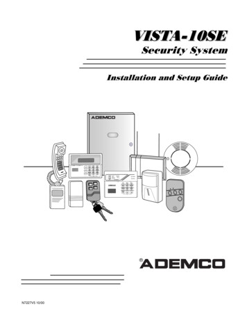
VISTA-128FBPVISTA-250FBPCommercial Fire and BurglaryPartitioned Security System with SchedulingInstallation and Setup GuideK0376V2 7/09 Rev. B
Table of Contents Commercial Fire and Burglary. iGeneral Requirements . ixProgramming Field Settings for UL864 Compliance. ixSECTION 1. 1-1SIA Installations .1-1About the VISTA-128FBP/VISTA-250FBP .1-1Features .1-1Guidelines for Wiring a System .1-3SECTION 2. 2-1Theory of Partitioning.2-1Setting-Up a Partitioned System .2-1Common Lobby Logic .2-1Master Keypad Setup and Operation .2-3SECTION 3. 3-1Mounting the Control Cabinet .3-1Installing the Cabinet Lock .3-1Mercantile Premises Listing Guidelines.3-1Mercantile Safe and Vault Listing Guidelines .3-2Commercial Fire Guidelines .3-2Installing the Control's Circuit Board .3-3Installing the Keypads .3-3Installing External Sounders .3-4Auxiliary Relay Connections .3-8Telephone Line Connections.3-9Main Dialer Connections .3-9Wiring Burglary and Panic Devices to Zones 1-8.3-11Installing V-Plex Devices.3-15Wireless Zone Expansion .3-18Installing Output Devices.3-22Installing a Remote Keyswitch.3-23Installing a Remote Keypad Sounder (For Commercial Burglary use only) .3-24Communicators Connected to the ECP.3-25Event Log Connections .3-26Connecting the Transformer .3-26Earth Ground Connections .3-27Determining the Control’s Power Supply Load.3-28Determining the Size of the Standby Battery .3-30SECTION 4. 4-1Program Modes.4-1Entering and Exiting Programming Mode .4-1Data Field Programming Mode .4-1#93 Menu Mode Programming .4-2Zone Number Designations .4-4iii
Table of ContentsZone Response Type Definitions.4-6Zone Input Type Definitions.4-8Programming for Communicator .4-9Programming for the Event Log.4-9SECTION 5. 5-1About Data Field Programming .5-1Programming Data Fields .5-1SECTION 6. 6-1Time Window Definitions .6-2Open/Close Schedules Definitions.6-3Scheduling Menu Mode.6-4Time Windows .6-5Daily Open/Close Schedules .6-6Holiday Schedules .6-6Time-Driven Events .6-7Limitation of Access Schedules .6-11Temporary Schedules.6-12User Scheduling Menu Mode.6-14SECTION 7. 7-1General Information.7-1Unattended Download (For Burglary Use Only) .7-1Getting On-Line with a Control Panel.7-3Scheduled Download (For Burglary Use Only) .7-4Direct-Wire Downloading .7-4Telco Handoff.7-4SECTION 8. 8-1General Information.8-1Setting the Time and Date .8-1SECTION 9. 9-1General Information.9-1User Codes and Levels of Authority.9-1Multiple Partition Access.9-2Adding a Master, Manager, or Operator Code .9-3Changing a Master, Manager, or Operator Code.9-4Deleting a Master, Manager, or Operator Code .9-4Exiting the User Edit Mode.9-4SECTION 10. 10-1Battery Test .10-1Dialer Test .10-1Fire Drill Test (Code [#] 69) .10-1One-Man Fire Walk-Test (Code [#] 68) .10-1Burglary Walk-Test (Code [5] TEST).10-2Armed Burglary System Test .10-3Testing Wireless Transmitters .10-3Trouble Conditions .10-4To the Installer .10-5APPENDIX A.A-1iv
Table of ContentsUL Installation Requirements. A-1UL864/NFPA Local Fire . A-1UL864/NFPA Central Station and Remote Station Fire . A-1UL609 Local Mercantile Premises/Local Mercantile Safe & Vault . A-1UL365 Police Station Connected Burglar Alarm . A-2UL1610 Central Station Burglary Alarm . A-2California State Fire Marshal (CSFM) Requirements. . A-2APPENDIX B.B-1APPENDIX C.C-1APPENDIX D . D-1TABLE OF CONTACT ID EVENT CODES . D-1Event Log Alpha Descriptors. D-2v
List of Figures Figure 1-1: Isolating Fire Devices from Burglary Devices.1-4Figure 3-1: Installing the Lock.3-1Figure 3-2: Cabinet Attack Resistance Considerations .3-2Figure 3-3: Commercial Fire Installation Considerations .3-2Figure 3-4: Mounting the PC Board.3-3Figure 3-5: Keypad Connections to Control Panel .3-4Figure 3-6. ECP Isolator Wiring .3-4Figure 3-7: This Figure Intentionally Left Blank .3-4Figure 3-8: Wiring Auxiliary Relay for Alarm Activation.3-8Figure 3-9: Wiring Auxiliary Relay for Smoke Detector Reset.3-9Figure 3-10: 2-Wire Smoke Detector on Zone 1 (for zone 2 use terminals 17 and 18).3-12Figure 3-11: 4-Wire Smoke Detectors .3-13Figure 3-12. Wiring Latching Glassbreaks to Zone 8.3-14Figure 3-13: Wiring a Normally Closed Sensor Loop for Tamper Supervision.3-14Figure 3-14: Wiring a Normally Open Sensor Loop for Tamper Supervision .3-15Figure 3-15: Polling Loop Connections to the Control Panel.3-17Figure 3-16: Polling Loop Connections Using One 4297 Extender Module .3-17Figure 3-17: Polling Loop Connections Using Multiple Extender Modules .3-18Figure 3-18: Installing the 5881ENHC with Tamper Protection .3-19Figure 3-19: 5881 RF Receiver (cover removed) .3-20Figure 3-20: 4204 Relay Module.3-22Figure 3-21: 4204CF Relay Module.3-23Figure 3-22: Remote Keyswitch Wiring .3-24Figure 3-23: Remote Keypad Sounder Wiring.3-24Figure 3-24: Wiring Communicator to Keypad Terminals .3-26Figure 3-25: Connecting the Backup Batteries .3-31VISTA-128FBP/ VISTA-250FBP Summary of Connections Diagram.Inside Back Covervi
Conventions Used in This Manual Before you begin using this manual, it is important that you understand the meaning of the following symbols (icons).ULThese notes include specific information that must be followed if you are installing this system fora UL Listed application.These notes include information that you should be aware of before continuing with theinstallation, and that, if not observed, could result in operational difficulties.!This symbol indicates a critical note that could seriously affect the operation of the system, orcould cause damage to the system. Please read each warning carefully. This symbol alsodenotes warnings about physical harm to the user.ZONE PROG?1 YES 0 NO 0 00Many system options are programmed in an interactive mode by responding toalpha keypad display prompts. These prompts are shown in a single-line box.Additional system options are programmed via data fields, which are indicated by a “star”( ) followed by the data field number.PRODUCT MODEL NUMBERS:Unless noted otherwise, references to specific model numbers represent Honeywell products.vii
viii
UL864 (Commercial Fire) Compliance General RequirementsThe VISTA-128FBP/VISTA250FBP control panels provide features that allow the system to meet UL864 CommercialFire requirements. To meet these requirements, follow the guidelines outlined in this section. The reporting of bypassed points to the central station must be enabled in Report Code Programming mode.Fire alarm notification circuits must be supervised (e.g., supervisory zones 970 and 971 for Bell 1 and Bell 2 outputs)Only one relay of the 4204CF can be programmed for a NAC. If the 4204CF relay is programmed as a NAC, the stopaction must be programmed as a zone type 62, Bell 2 Timeout.Output devices are not intended for overriding automatic fire and building functions.Line cut detection must be enabled for both the main and backup phone lines (supervisory zones 974 and 975).Access Control Devices cannot be used.Audio Alarm Verification Devices cannot be used.Remote downloading can only be performed if a service person is at the premises.All supervision zones for the polling loop, RF receivers, keypads, NAC outputs, and telephone lines that are used, mustbe enabled as zone type 19 (24-hour trouble).Programming Field Settings for UL864 ComplianceNOTICE TO USERS, INSTALLERS, AUTHORITIES HAVING JURISDICTION, AND OTHER INVOLVEDPARTIESThis product incorporates field-programmable software. In order for the product to comply with the requirementsin the Standard for Control Units and Accessories for Fire Alarm Systems, UL 864, certain programming featuresor options must be limited to specific values or not used at all as indicated below.Program feature or optionPermitted inUL864? Y/NPossible settingsSettings permitted in UL 864 08 TEMPORAL SIRENPULSEN0 disable1 enableNot used at this time. Mustbe set to “0” (disable). 13 ALARM SOUNDER(BELL) TIMEOUTYMust be set to “3” (Minimumof 6 minutes). 14 TRIGGER OR RS232N 17 AC LOSS KEYPADSOUNDING 20 VIP MODULEPHONE CODENEnter 01-15 multiplied by 2minutes. 00 no timeout.0 trigger1 RS232 input0 disable1 enable1-9 first digit of access code or # second digit of accesscode (enter # 11 for “ ”, or # 12 for “#”).stTo disable enter 0 for the 1digit.0 disable1 enable 22 KEYPAD PANICENABLES (PARTITIONSPECIFIC) 23 MULTIPLEALARMS (PARTITIONSPECIFIC) 26 INTELLIGENT TESTREPORTINGNNMust be set to “0”.Must be set to “1” (enabled).Not used. Must be set to “00”.Must be set to “000” forpartition 1 in fire systems.N0 disable1 enableMust be set to “1” (enabled).N0 disable1 enableMust be set to “0” (disable).ix
Program feature or option 27 TEST REPORTINTERVAL 28 POWERUP INPREVIOUS STATE 37 DOWNLOADCOMMAND ENABLES 41 NORMALLYCLOSED OR EOLR(ZONES 3-8) 42 DIAL TONE PAUSEPermitted inUL864? Y/NYYNNY 44 RING DETECTIONCOUNTN 54 UNATTENDEDMODE 56 DYNAMICSIGNALING DELAY 77 AUTO TROUBLERESTORE 80 ZONE TYPERESTORES FOR TYPES9, 10 & 141 12 PROGRAMNOTIFICATION SIGNAL1 13 SYSTEM SENSORREVERSING RELAYN1 18 AFFECTS LOBBYN1 19 ARMS LOBBYN1 22 thru 1 25 CROSSZONING PAIRS (1 – 4)1 28 RF TRANSMITTERLOW BATTERY SOUNDN1 29 RF TRANSMITTERLOW BATTERYREPORTINGNxYYNPossible settingsSettings permitted in UL 864Enter 0001-9999 for the testreport interval in hours.Enter 0000 for test reporting.0 disable1 enable0 disable1 enable0 EOLR supervision1 N.C. loopsMust be set to “0024”(Maximum 24 hours)Enter the wait time for dialtone detection:0 5 seconds; 1 11 seconds;2 30 seconds.Enter 00 to disable ringdetection.Enter 01-14 for ring counts of1-14.Enter 15 to select AnsweringMachine Defeat Mode0 disable1 enableEnter 00-15 times 15 seconds.Must be set to “0” (5 seconds).0 disable1 enable0 disable1 enableMust be set to “1” (enable).Must be set to “0” for allentries (disable).Must be set to “0” (EOLRSupervision).Must be set to “00” (disable).Must be set to “0” (disable).Must be set to “6” (90seconds).Must be set to “1” (enable).Must be set to “1” (enable) forzone type 9.Y0 no1 yesMust be set to “1” (yes).N0 use neither Zone 1 or Zone2 inputs1 use Zone 1 input;2 use Zone 2 input;3 use Zone 1 and Zone 2inputs.0 disable1 enable0 disable1 enableEnter 001-250Enter 000,000 to disableNot Used. Must be set to “0”.0 disarmed state only1 both armed and disarmedstates0 disable1 enableMust be set to “1” (botharmed and disarmed states).NMust be set to “0” (disabled)for partition 1.Must be set to “0” (disabled)for partition 1.Must be set to “000,000”(disabled) for fire zones.Must be set to “1” (enable).
Program feature or option1 30 RF RECEIVERSUPERVISION CHECKIN INTERVALPermitted inUL864? Y/NN1 31 RF TRANSMITTERCHECK-IN INTERVALN1 35 ACCESS CONTROLDIALER ENABLESN1 44 WIRELESSKEYPAD TAMPERDETECT1 45 EXIT DELAYSOUNDING (PARTITIONSPECIFIC)1 48 WIRELESSKEYPAD ASSIGNMENTN1 49 SUPPRESS TXSUPERVISION SOUND1 53 DISABLEDOWNLOAD CALLBACK1 57 5800 RF BUTTONGLOBAL ARM1 58 5800 RF BUTTONFORCE ARM1 60 ZONE 5 AUDIOALARM VERIFICATION1 69 PRINTER TYPEPossible settingsSettings permitted in UL 864Enter 02–15 times 2 hours (4–30 hours)Enter 00 to disable receiversupervisionEnter 02–15 times 2 hours (4–30 hours)Enter 00 to disabletransmitter supervision0 disable1 enable0 disable1 enableMaximum is 02 (4 hours) forfire installations.Maximum is 02 (4 hours) forfire installations.Not used. Must be set to “0”.Not used. Must be set to “0”.N0 disable1 enableMust be set to “0” (disable)for partition 1.N0 none1-8 partition number0 disable1 enableNot used. Must be set to “0”.N0 callback required1 no callback requiredMust be set to “0” (callbackrequired).N0 disable1 enableMust be set to “0” (disable).N0 disable1 enableMust be set to “0” (disable).N0 disable1 enableMust be set to “0” (disable).N0 parallel printer1 serial printer0 disable1 enable0 12001 30001-96 relay number00 relay not used.Not used.NMust be set to “0” (disable).1 72 EVENT LOGPRINTER ONLINENNot used. Must be set to “0”.1 73 PRINTER BAUDRATEN1 76 CONTROL RELAY(PART-SPECIFIC)N1 78 EXTENDED HOMECONT EVENTS1 79 HOME CONTROLEVENTSN1 extended0 limitedNot used. Must be set to “0”.NNot used. Must be set to “0”in each entry.2 07 AUTO-DISARMDELAY (PARTSPECIFIC)N2 18 ENABLE GOTOFOR THIS PARTITION(partition-specific)N0 disable1 enable00 no delay.01-14 times 4 minutes (04-56)delay.15 no auto disarming.0 disable1 enableNot used.Must be set to “00” (relay notused) for partition 1.Must be set to “15” (no autodisarming) for partition 1.Must be set to “0” (disable)for partition 1.xi
Program feature or option2 21 SUPERVISIONPULSES FORPermitted inUL864? Y/NNPossible settingsSettings permitted in UL 8640 disable1 enableMust be set to “00000”(disable).N0 disable1 enableMust be set to “0” (disable)for partition 1.N0 disable1 enableMust be set to “0” (disable)for partition 1.N0 disable1 enableMust be set to “0” (disable)for partition 1.NNANot used. Must be set to “0”.N0 disable1 enableMust be set to “1” (enable).N0 disable1 enableMust be set to “0” (disable).N0 Trouble on open/Supv onshort1 Supv on open/Supv onshortMust be set to “0”.N0 Silenced by User Code OFF1 Silenced when zonerestoresEnter 01-15 times 2 secondsEnter 00 for no delayMust be set to “0” (Silencedby User Code OFF).COMMUNICATIONSDEVICE2 22 DISPLAY FIREALARMS OF OTHERPARTITIONS2 23 DISPLAY BURG,PANIC AND CO ALARMSFOR OTHERPARTITIONS2 24 DISPLAYTROUBLES OF OTHERPARTITIONS2 30 THROUGH 2 88(PAGER OPTIONS)3 01 EVENTS DISPLAYLOCK3 12 ZN TYPE 18 DELAYUSE3 13 FIRESUPERVISORYRESPONSE TOOPEN/SHORT (APPLIESTO ZONE TYPE 18)3 14 WATERFLOWALARM SILENCEOPTION3 16 DELAY FOR ZONETYPES 17 & 18(Waterflow/Supervisory)3 18 EXTENDEDDELAY FOR ZONETYPES 17 & 18 Multipliesdelay in 3*16 x 4)3 19 AUXILIARY INPUTALTERNATE FUNCTIONENABLE3 20 TRIGGEROUTPUTS FUNCTIONSELECTION3 21 MAXIMUMNUMBER OF DIALERATEMPTS3 50 ZONE TYPERESTORE ENABLESFOR TYPES 16-18xiiNMust be set to 00 (no delay).N0 no extended delay1 multiply delay by 4Must be set to 0 (no extendeddelay).N0 disable1 enableMust be set to 0 (disable).N0 remote keypad sounder1 keyswitch LEDsMust be set to 0 (remotekeypad sounder).Y1-8Must be set at 3, 4 or 5.N0 disable1 enableMust be set to “1” (enable).
Program feature or option3 60 BELL 2 & AUXRELAY TIMEOUT3 82 ENABLEBURGLARY FEATURESON PARTITION 1RESTRICTION FOR FIRERELAYSPermitted inUL864? Y/NYNYPossible settingsSettings permitted in UL 864Enter 01-15 multiplied by 2minutes.00 no timeout.0 disable1 enableMust be set to “3” (Minimumof 6 minutes).YesNoRestriction for # 70 must beset to Yes whenprogramming fire relays.Must be set to “0” (disable).xiii
xiv
S E C T I O N1General Description
This product incorporates field-programmable software. In order for the product to comply with the requirements in the Standard for Control Units and Accessories for Fire Alarm Systems, UL 864, certain programming features or options must be limited to specific values or not used at all as indicated below. Program feature or option Permitted in
