Transcription
ADEMCO VISTA SERIESVISTA-21iP / VISTA-21iPSIASecurity SystemsInstallation and Setup GuideK14488V1 7/08 Rev. B
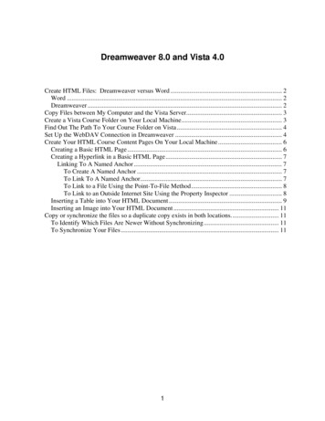
RECOMMENDATIONS FOR PROPER PROTECTIONThe Following Recommendations for the Location of Fire and Burglary Detection DevicesHelp Provide Proper Coverage for the Protected Premises.Recommendations For Smoke And Heat DetectorsWith regard to the number and placement of smoke/heat detectors, we subscribe to the recommendationscontained in the National Fire Protection Association's (NFPA) Standard #72 noted below.Early warning fire detection is best achieved by the installation of fire detection equipment in all roomsand areas of the household as follows: For minimum protection a smoke detector should be installedoutside of each separate sleeping area, and on each additional floor of a multi-floor family living unit,including basements. The installation of smoke detectors in kitchens, attics (finished or unfinished), or ingarages is not normally recommended.For additional protection the NFPA recommends that you install heat or smoke detectors in the livingroom, dining room, bedroom(s), kitchen, hallway(s), attic, furnace room, utility and storage rooms,basements and attached garages.In addition, we recommend the following: Install a smoke detector inside every bedroom where a smoker sleeps. Install a smoke detector inside every bedroom where someone sleeps with the door partly orcompletely closed. Smoke could be blocked by the closed door. Also, an alarm in the hallway outsidemay not wake up the sleeper if the door is closed. Install a smoke detector inside bedroomswhere electrical appliances (such asportable heaters, air conditioners orKITCHENKITCHEN DININGBDRMBEDROOM BEDROOMTV ROOMDININGhumidifiers) are used.LIVING ROOMBDRMBEDROOMBEDROOMLIVING ROOMSmoke Detectors for Minimum ProtectionSmoke Detectors for Additional ProtectionHeat-Activated DetectorsBEDROOMBEDROOMTOBRBEDROOMKTCHNLVNG RM.CLOSEDDOOR Install a smoke detector at both ends of ahallway if the hallway is more than 40feet (12 meters) long. Install smoke detectors in any room wherean alarm control is located, or in any roomwhere alarm control connections to an ACsource or phone lines are made. Ifdetectors are not so located, a fire withinthe room could prevent the control fromreporting a fire or an intrusion.GARAGEBASEMENTfloor plan-001-V1THIS CONTROL COMPLIES WITH NFPAREQUIREMENTS FOR TEMPORAL PULSESOUNDING OF FIRE NOTIFICATIONAPPLIANCES.Recommendations For Proper Intrusion ProtectionFor proper intrusion coverage, sensors should be located at every possible point of entry to a home orcommercial premises. This would include any skylights that may be present, and the upper windows ina multi-level building.In addition, we recommend that radio backup be used in a security system so that alarm signals canstill be sent to the alarm monitoring station in the event that the telephone lines are out of order (alarmsignals are normally sent over the phone lines, if connected to an alarm monitoring station).ii
Table Of ContentsSection 1. Features and Installation Highlights. 1-1Capabilities and Functions . 1-1Compatible Devices . 1-2Important Installation Highlights (Installer Please Read). 1-2Section 2. Mounting and Wiring the Control . 2-1Installing the Control Cabinet and PC Board . 2-1Cabinet and Lock. 2-1Mounting the PC Board Alone (no RF Receiver) . 2-1Mounting Board with RF Receiver . 2-1AUXILIARY DEVICE CURRENT DRAW WORKSHEET . 2-2AC Power, Battery, and Ground Connections . 2-31361 Transformer . 2-31361X10 Transformer . 2-3Battery Connections . 2-3Battery Saver Feature. 2-3Earth Ground. 2-3Sounder (Bell) Connections . 2-4Basic Connections. 2-4Supervised output . 2-4Connecting the Keypads and Other Addressable Devices . 2-4Connections. 2-4Supplementary Power (optional) . 2-4Keypad Notes. 2-5Optional VISTA-GSM Module . 2-5Table of Device Addresses. 2-5Hardwire Zones and Zone Expansion . 2-6Hardwire Zones . 2-6Double-Balanced Zones . 2-6Zone Doubling. 2-6Smoke Detectors . 2-6Smoke Detector Notes . 2-74219/4229 Expansion Zones. 2-7Installing the RF Receiver and Wireless Transmitter Zones. 2-8Compatible Receivers . 2-8Receiver Connections . 2-8RF Receiver Notes . 2-8Installing a 5800TM Module. 2-9Installing the Transmitters . 2-9Transmitter Battery Life . 2-9Installing a Keyswitch . 2-10Keyswitch Connections . 2-10Keyswitch Notes . 2-10Connecting Relay Modules, Powerline Carrier Devices and Output Triggers . 2-114204/4229 Relay Modules. 2-11Powerline Carrier Devices . 2-11On-Board Triggers. 2-12Phone Line/Phone Module, Audio Alarm Verification (AAV), and Internet (IP) Connections . 2-13Phone Line . 2-134286 Phone Module . 2-13Phone Module Problems. 2-13Audio Alarm Verification Connections . 2-14Internet (IP) Connection . 2-15VISTA-GSM Module Installation . 2-15General Information. 2-15Mounting the Module . 2-15IP/GSM Status LEDs . 2-17Signal Strength (RSSI). 2-17Signal Strength (RSSI) and Status LEDs . 2-17Status Indicator Switch. 2-17Signal Strength and Status LED locations – Status LED Functions Table. 2-18iii
Section 3. Programming Overview . 3-19About Programming. 3-19Mechanics of Programming . 3-19Data Field Programming Procedures . 3-19Interactive Mode Programming ( 56, *57, 58, 79, 80, 81, 82) . 3-20Loading Factory Defaults/Initializing for Download . 3-20Exiting the Programming Mode . 3-20Zone Type Definitions . 3-20Section 4. Data Field Programming . 4-1About Data Field Programming . 4-1System Setup Fields ( 20 – 29). 4-1Zone Sounds & Timing ( 31– 39). 4-1Dialer Programming ( 40 – 50) . 4-2System Status Report Codes . 4-4Miscellaneous System Fields. 4-5Pager Programming Fields . 4-7Miscellaneous System Fields. 4-8Configurable Zone Type Fields . 4-9Touch Screen Keypad (AUI) Enable. 4-11Keypad Programming Fields . 4-11Section 5. Menu Mode Programming . 5-1Zones and Partitions . 5-1About Zone Programming ( 56 and 58 Menu Modes). 5-1 56 Zone Programming Procedure . 5-1Completing Zone Programming. 5-4 58 Expert Programming Mode Procedures . 5-4Wireless Key Programming Templates. 5-6About Output Device Programming (*79/*80 Menu Mode) . 5-8Programming Output Devices . 5-8*79 Menu Mode: Output Device Mapping. 5-8*80 Menu Mode: Defining Output Functions. 5-10About Zone Lists (*81 Menu Mode) . 5-12Zone List Programming . 5-13About Function Keys (*57 Menu Mode) . 5-14Programming Function Keys. 5-14About Descriptor Programming (*82 Menu Mode). 5-15Programming Zone Descriptors (Menu Mode 82) . 5-15Adding Custom Words (will not be annunciated by 4286 Phone Module). 5-16 29 Menu Mode for IP and GSM Module Programming . 5-18IP/GSM Diagnostic Commands ( 29 Menu Mode). 5-23Registering the Control with AlarmNet. 5-25Upload/Download via the Internet . 5-25Programming Installer and User Schedules. 5-26Section 6. System Communication and Operation . 6-1Panel Communication with Central Station. 6-1Report Code Formats . 6-1Ademco Contact ID . 6-3System Security Codes. 6-4Panic Keys . 6-6Setting the Real-Time Clock. 6-6Various System Trouble Displays . 6-7Section 7. Testing the System. 7-1About Test Procedures . 7-1System Test . 7-1Checking Transmitter Enrollment (Sniffer Mode) . 7-1Go/No Go Test Mode. 7-2Dialer Communication Test and Periodic Test Reports . 7-2Automatic Standby Battery Tests . 7-2Section 8. Specifications & Accessories. 8-1Security Control . 8-1Compatible Devices . 8-15800 Series Transmitter Input Loop Identification. 8-3Section 9. Regulatory Agency Statements . 9-1Section 10. Limitations and Warranty . 10-1iv
S E C T I O N1Features and Installation HighlightsFeatures and procedures apply to both the VISTA-21iP and VISTA-21iPSIA, except where differencesare noted.SIA Installations: The VISTA-21iPSIA is a certified SIA-compliant control that meets SIAspecifications for False Alarm Reduction. The VISTA-21iP is not certified as SIA-compliant, but canbe programmed for False Alarm Reduction. To program for False Alarm Reduction, follow the SIAGuidelines noted in the applicable programming fields.NOTE: Throughout this manual, device model numbers are ADEMCO model numbers unlessotherwise noted.Capabilities and FunctionsFeature/FunctionPartitionsZonesSecurity CodesOne-button armingSchedulesKeypad macrosPagingEvent LoggingZone descriptorsBell supervisionRF jam detectionTelephone LineMonitoringDownloading viaPhone Line orInternetInternet ReportingDescription 2 partitions, can protect two independent areas Common zone option allows either partition to arm, while leaving a common area(ex. lobby or foyer) disarmed for access into the other partition.Up to 48 protection zones plus 16 keyfob zones (zones 49-64) for total of 64 zones: 8 basic hardwired zones (zones 1-8) with optional zone-doubling feature Up to 40 additional wired zones (zones 9-48) using up to 5 4219/4229 modules Up to 40 wireless transmitter zones (5800 series; zones 9-48) Up to 4 configurable zone typesUp to 48 Security Codes, with separate authority levels and partition accessDedicated keys can arm the system.Up to 32; can control devices and/or auto-arm/disarmUp to 4; activated by wired keypadsUp to 4 pagers; certain system conditions can report to pagers; can use a dedicatedkey on keypads to send a signal to a pager100 events; log display is done via Compass Downloader software or installer/mastercode at KeypadCan assign for all zones (for alpha display keypads and/or 4286 Phone Module).Optional, detects external sounder wiring short (when in alarm) or open (when bell isoff); causes a trouble condition, keypad display, and sends a report to the centralmonitoring station, if enabled.Optional, for wireless systems detects a condition that may impede proper RFreception (i.e., jamming or other RF interference); causes keypad display, and sends areport to the central monitoring station (if trouble reporting is enabled).Built-in option can monitor the telephone line voltage and can cause a local display,or a display and trouble/alarm sound Via Standard Phone Line: Using an IBM compatible computer, Compassdownloading software, and a compatible HAYES or CIA modem specified byHoneywell. Via Internet: Supports upload/download programming capability via the Internetusing the AlarmNet network and Compass downloading software. This allows sitemaintenance independent of central station monitoring, and modification to sitesglobally via the Internet. Also see Internet Reporting below and InternetConnection on the next page.Primary telephone number messages can be reported over the Internet via hardwiredhigh speed Internet connection and/or via an optional on-board VISTA-GSM module(using the wireless GSM/GPRS digital cellular network). The Internet connection andoptional module are collectively referred to as the Internal IP/GSM Device.1-1
Installation and Setup GuideCompatible DevicesDeviceAddressable KeypadsTouch Screen (AUI)Devices4219, 4229 ZoneExpander Modules5800 Series WirelessOutput relays and/orPowerline CarrierDevices (X-10 type)On-Board TriggersOutput functions4286 Phone ModuleLimits84Up to 5 forup to 40exp. zonesUp to 40 RFzonesUp to 162Up to 48Partition 1onlyAudio AlarmVerificationUsing AAVmoduleAlarm output12VDC, 2AMP outputAuxiliary Power OutputBackup BatteryInternet Connectionand Optional VISTAGSM ModuleAC Power SupplySee note.See note.See note.See note.Notes6150 Fixed-Word Keypad, 6160 Alpha Keypad, 6150V Fixed-WordDisplay Voice Keypad, 6160V Alpha Display Voice Keypad,6150RF Keypad/TransceiverTouch Screen (AUI) devices are in addition to the 8 addressablekeypads. E.g., Symphony, 6270Zone numbers are predefined according to the device addressesused. See Expander Module Addresses table in Wiring section andset addresses accordingly.Uses 5881/5883 Series Receivers/Transceivers.Use any combination of 4204, 4229 and or Powerline CarrierDevices.Map output devices via *79 Menu mode.Can be used to reset 4-wire smoke detectors.Program output functions via *80 Menu mode.Provides access to the system via on premises or off-premisesphones for arming, disarming, etc., plus control of relay outputsand Powerline Carrier devices.Use ADEMCO UVS or Eagle Model 1250; can be used inconjunction with an output trigger to permit voice dialog betweenan operator at the central station and a person at the premises.Can drive the compatible sounders; steady output forburglary/panic, or temporal pulse (3 pulses – pause – 3 pulses –pause – 3 pulses. . .) for fire. Uses current limiting circuitry forprotection.12VDC, 600 mA maximum; uses fuse for protection.Rechargeable (sealed lead-acid type) 12VDC, 4AH minimum.Internet connection is made via an on-board Ethernet connectorfor high speed (broadband) hardwire connections, and/or use ofthe optional on-board VISTA-GSM module.Plug-in 120VAC transformer, ADEMCO 1361 (1361CN inCanada) or, if using Powerline Carrier devices, ADEMCO1361X10 Transformer ModuleNOTE: All devices and accessories used in a Canadian installation must be Listed for use in Canada.Important Installation Highlights (Installer Please Read) This system uses addressable keypads and Zone Expander Modules (see Table of Addresses inSection 2. Mounting and Wiring – Wiring the Keypads and Other Addressable Devices). Keypads must be set for addresses 16-23 (first keypad is address 16, which is different fromprevious controls) and programmed in data fields *190-*196. Zone Expander Modules must be set for specific addresses (07-11), based on the zone numbers used. 4204 Relay Modules must be set for specific addresses (12-15). This control will not power-up unless AC power is connected (will not power-up on battery alone).However, once the system is powered up, it will operate on battery power in the event of AC loss. Relays have two programming menu modes: Use *79 Menu mode to map module addresses anddevice (output) numbers. Use *80 Menu mode to define the output functions. This system supports programmable function keys. Use *57 Menu mode to define the functionkeys. This system provides various paging features. Refer to the Programming Overview section for asummary on pager programming.1-2
S E C T I O N2Mounting and Wiring the ControlInstalling the Contro
VISTA-21iP / VISTA-21iPSIA Security Systems Installation and Setup Guide K14488V1 7/08 Rev. B . For proper intrusion coverage, sensors should be located at every possible point of entry to a home or commercial premises. This would include any skylights that may be present, and the upper windows in .