Transcription
Keyboard ControllerPIH-931D/932TMERIT LI-LIN ENT. CO., LTDhttp://www.meritlilin.com66-931CSEINSTRUCTION MANUAL
IMPORTANT SAFEGUARDS1. Read InstructionsAll the safety and operating instructions should be read before the unit is operated.2. Retain InstructionsThe safety and operating instructions should be retained for future reference.3. Head WarningsAll warnings on the unit and in the operating instructions should be adhered to.4. Follow InstructionsAll operating and user instructions should be followed.5. Electrical ConnectionsOnly a qualified electrician should make electrical connections.6. AttachmentsDo not use attachments not recommended by the product manufacturer as they may cause hazards.7. Cable RunsAll cable runs must be within permissible distance.8. MountingThis unit must be properly and securely mounted to a supporting structure capable of sustaining the weightof the unit.SAFETY PRECAUTIONSCAUTIONRISK OF ELECTRIC SHOCKCAUTIONTO REDUCE THE RISK OF ELECTRIC SHOCK,DO NOT OPEN COVER.NO USER SERVICEABLE PARTS INSIDE.REFER SERVICING TO QUALIFIED SERVICE PERSONNEL.The lightning flash with arrowhead symbol, within anequilateral triangle, is intended to alert the user to thepresence of uninsulated "dangerous voltage" within theproduct's enclosure that may be of sufficient magnitudeto constitute a risk of electric shock to persons.The exclamation point within an equilateral triangle isintended to alert the user to the presence of importantoperating and maintenance (servicing) instructions inthe literature accompanying the unit.UNPACKINGUnpack carefully. Electronic components can be damaged if improperly handled or dropped. If an item appearsto have been damaged in shipment, replace it properly in its carton and notify the shipper.Be sure to save:1. The shipping carton and packaging material. They are the safest material in which to make future shipmentsof the equipment.2. This Installation and Operating Instruction.SERVICEIf the unit ever needs repair service, the customer should contact our dealer or branch for authorization toreturn and shipping instructions.
PREFACEThank you for choosing PIH-931D/932T keyboard controller. For trouble free installation and optimumperformance please read this manual thoroughly before attempting installation or operation.CONTENTS1. Introduction . 22. Specifications . 23. Keyboard Layout . 34. Keypad Panel . 45. Joystick Operation (Pan/Tilt/Zoom Control) . 66. Keyboard System Setting . 67. Fast Dome Operation . 98. Matrix and Receiver Operation . 119. DVR Operation . 1310. Wiring Diagrams . 1611. Product Components . 1612. System Overview and Wiring . 171
INTRODUCTIONThe PIH-931D/932T is a keyboard controller for a range of matrix switchers, dome cameras, DVR andtelemetry receivers. It allows operation all the functions of equipment and provides a simple operatorinterface.When matrix is present in the system, up to 8 keyboards can be used. However, one of the keyboardsmust always be configured as the Master, having greater access to settings than the slaves.Data is transmitted via screened, twisted pair cables, usually in serial configuration. (RS-485)SPECIFICATIONSModel No.JoystickPIH-931DPIH-932T3 Axis (Pan/Tilt/Zoom)2 Axis (Pan/Tilt)PanMovement Speed Control8 StepsPanTilt 8 StepsZoomTilt 8 Steps16 StepsData Communication(FormatRS-485 StandardN, 8, 1, Baud rate 9600bps)ConnectorRJ-45 / 8PinControl ModePTZLCD DisplayKeyboard KeypadMATRIX DVR20 Characters x 4 LinesTotal 54 keys 0 9 Numeric Keys, CAM, MON,MATRIX, DVR, PRESET, CLR, ENT, SET, ESC,ALARM RESET, KEYLOCK, SEQ, AUTO PAN andSHIFT Keys, Lens Control Keys, DVR control Keys,Receiver Control Keys, Function KeysInput VoltageDC 12V 10% / 250mAPower Consumption3WOperating Temperature-5 60(23 140)340(W) x 194(D) x 103(H) mmDimensionWeight8 Steps1350 g21300 g
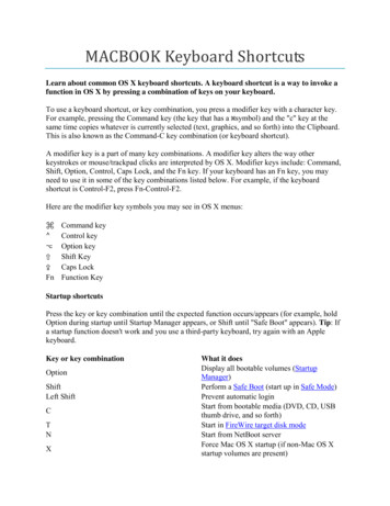
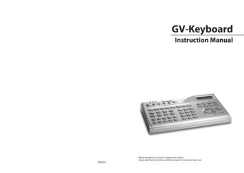
KEYBOARD LAYOUTPOWER06/02/15 12 00 00PTZ MODE ID TOFOCUSAUTOIRIS0LCD DisplayDisplay the Keyboard system setup menu and operation information.Joystick3 Axis(Pan/Tilt/Zoom) / 2 Axis(Pan/Tilt)Keypad PanelThere are 54 Keys which can control PTZ, MATRIX, DVR and Telemetry Receivers.Power IndicatorAlarm IndicatorR/T IndicatorData communicate indication.Auto pan IndicatorSHIFT IndicatorShift key status indication.Auto focus IndicatorAuto iris IndicatorRJ-45 Connector3
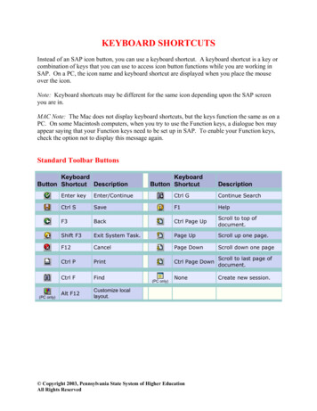
KEYPAD SAUTOIRIS0SET keyEnter Setup Menu Mode.ESC keyUse to exit from any function or programming.ALARM RESET keyReset alarms and video loss alarms.2009/01/01 12 00 00(Keyboard Lock) keyPresskey for 2 second to enter locking mode. PressKEYPAD LOCKkey again for 2 second to unlock the keypad.Presskey in PTZ mode, the keyboard will leave the control over cameras.2009/01/01 12 00PTZ MODE ID XX002009/01/01 12 00PTZ MODE ID 0000CAM keySelect a particular camera.Or press SHIFT CAM button to switch to PTZ(Fast Dome) control mode.DVR keySelect a particular DVR.Or press SHIFT DVR button to switch to DVR control mode.MON keySelect a particular monitor.MATRIX keyPress SHIFT MATRIX button to switch to Matrix control mode.PRESET keyFor recalling and storing preset positions.FUNCTION keysThere are 4 function keys (F1, F2, F3 and F4) to execute different functions under differentoperation modes.Numeric keys0 9 for entering camera, monitor, DVR number etc.4
CLR keyClear to setting data.ENT keyUsed to enter or confirm data and programming.WIPER / LENS keyThe command key of housing wiper when keyboard connects to PIH-820 (Receiver).* Manual speed switch of Zoom, Focus and Iris when keyboard connects to Fast Dome Camera).SPRAY / ICR keyThe command key of spray to housing.* Manual IR Cut Filter Swap when keyboard connects to Fast Dome Camera).LIGHT / C.ESC keyAuxiliary lighting switch when keyboard connects to PIH-820 (Receiver).* OSD Setup Menu exit key when keyboard connects Fast Dome Camera).CTRL 1 / C.SET keyA spare control key when keyboard connects to PIH-820(Receiver) or Matrix.* OSD Setup Menu recall key when keyboard connects to Fast Dome Camera).CTRL 2 / 180 keyA spare control key when keyboard connects to PIH-820(Receiver) or Matrix.* 180 Horizontal Instant Flip key when keyboard connects to Fast Dome Camera.SEARCH keyPerform date and time search based on recorded video data when keyboard connects to DVR.SHIFT keyPress SHIFT key to switch and match other buttons to execute different functions.AUTO PAN keyPut a Pan/Tilt head into auto pan mode or a Fast Dome Camera into auto tour mode.SEQ keyStart an automatic switching sequence on a particular monitor.(Matrix)(ZOOM IN / ZOOM OUT) keysAdjust the zoom of the lens manually.FOCUS FAR / FOCUS NEAR keysAdjust the focus of the lens manually.AUTO FOCUS keySet the focus of the lens to automatic mode when connects to Fast Dome Camera.(IRIS OPEN / IRIS CLOSE) keysOpen or close the iris of the lens manually.AUTO IRIS keySet the iris of the lens to automatic mode.DVR Control keysDVR operational keys including 4, 8, 9, 16 split display, record, playback, pause, stop, fastforward and fast rewind.5
JOYSTICK OPERATION (Pan/Tilt/Zoom Control)1. The joystick can be used to control the Fast Dome Camera's left, right, up and down movements.3 Axis2 Axis2. The joystick can be used to control Fast Dome Camera's zoom in and zoom out function.Stick turn counter-clockwise to zoom out.Stick turn clockwise to zoom in.KEYBOARD SYSTEM SETTINGPress SHIFT SET button to activate the Keyboard system setup menu. Tilt the joystick up or downto select the menu setup page. Press the 1 11 button to set the number of the desired sub setup item.Press the ESC button to exit the sub setup item or keyboard system setup menu.MENU SETUP 1/41. KEYBOARD ID2. SYSTEM MODE3. PROTOCOLMENU SETUP 3/47. DATE FORMAT8. DISPLAY9. TRANSMISSIONMENU SETUP 2/44. TONE5. DATE/TIME6. SUMMER/TIMEMENU SETUP 4/410. INFORMATION11. BAUD RATE1. KEYBOARD IDWhen use multi-keyboard or under MATRIX control mode, haveto setup Keyboard ID.Press the 1 8 button to set the Keyboard ID number.6KEYBOARD ID SETUPSelect (1-8) for IDID 1
With one keyboard, it will be compelled to be the master control and the ID number 1.With muti-keyboard, the ID number can not be repeated. The first one will be compelled to bethe master controller and the ID number 1.The maximum number of keyboard connections is according to the system mode8 in PTZ/Matrix mode, 4 in DVR mode.2. SYSTEM MODESelect the system operation mode of the Keyboard controller bytilting the Joystick left or right to change the operation mode.(PTZ Ö DVR Ö MATRIX)SYSTEM MODE SETUPMove L/R Select ModePTZ MODE3. PROTOCOLSelect the protocol of the operation mode, press the 1 3 buttonto select the operation mode.Press the 1 button to set the protocol type for PTZ mode,press the 1 5 button to select protocol type.* Press the 1 button to select the protocol for the MLP1(PIH-7625 etc.)* Press the 2 button to select the protocol for the MLP2(PIH-7622/35; SP203x/212x etc.)Push the joystick down to select the next page* Press the 3 button to select the protocol for the MLP2(PIH-7625T)* Press the 4 button to select the protocol for the PELCO-D* Press the 5 button to select the protocol for the PELCO-PPROTOCOL SETUP1. PTZ2. DVR3. MATRIXPTZ MODE1. MLP1 (PIH-7625 etc.)2. MLP2 (PIH-7622/35/SP203x/212x etc.)PTZ MODE3. MLP2 (PIH-7625T)4. PELCO-D5. PELCO-PPTZ MODE6. SDII CONVENTIONAL7. SDII (WV-CS850/860)8. SDIII (WV-CS950)Push the joystick down to select the next page* Press the 6 button to select the protocol for the PANASONIC SDII CONVENTIONAL* Press the 7 button to select the protocol for the PANASONIC SDII (WV-CS850/860)* Press the 8 button to select the protocol for the PANASONIC SDIII (WV-CS950)Note: If select the protocol for the PELCO-D/P or PANASONIC CONVENTIONAL / WV-CS850/860/ WV-CS950, need going to the eleventh item of menu setup to select the transmission speed(BAUD RATE).Press the 2 button to set the protocol for DVR mode.* Press the 1 button to select the protocol for PDR-2160.DVR MODE1. PDR-2160Press the 3 button to set the protocol for MATRIX mode.* Press the 1 button to select the protocol for PIH-816/832/864.MATRIX MODE1. PIH-816/832/864Note Once the setup is completed, the display will return backto previous setup screen. The setup data will be saved onEEPROM.7
4. TONETONE SETUPKeypad tone and Alarm tone ON/OFF control.Press Digit ON/OFFKeypad Tone1. Keypad tone : ONPress the 1 button to turn on or turn off the buzzer for keypad2. Alarm tone : ONtone.Note Keypad tone ON, when properly operation of keyboard controller, it will send out bi-bi soundto confirm. If wrongful usage, it will send out bi-bi-bi sound to respond.However, keypad tone OFF, there is no "bi" sound respond.Alarm TonePress the 2 button to turn on or turn off the siren speaker for alarm tone.5. DATE / TIMEDate and Time setting, press a number on number pad to enterthe date and time, used the Joystick left or right to move thecursor position and press the ESC button to finish the setup.Note The setup Date format is YY/MM/DD.6. SUMMER/TIMEDaylight saving time function setting.Press the 1 button to set the daylight saving time setting.To push the joystick left or right to move the cursor position,and the press the number key to set the date and time. Then,press the ENT to next page, or press ESC to complete thesetup.S: Start time setting.E: End time setting.CORRECT: Correct setting the daylight saving start time.ENT: Next page.ESC: Complete the SUMMER/TIME setup.DATE / TIME SETUP09/01/01 120000SUMMER/TIME SETUP1. ON2. OFF3. CLEARS: 09/04/05E: 09/10/25CORRECT:PAGE1 ENT: S05:00:0023:59:0006:00:00ESC: CNote: The setup date format is YY/MM/DD.Press the 2 button to turn off the daylight saving time setting.Press the 3 button to clear the daylight saving time setting.7 . DATE FORMATSelect the Date display format, press the 1 3 button to selectthe display format.DATE FORMAT1. YYYY/MM/DD2. MM/DD/YYYY3. DD/MM/YYYY8. DISPLAYSetup Time display ON/OFF.Time displayPress the 1 button to turn on or turn off the time display onthe LCD.DISPLAY SETUPPress Digit ON/OFF1. Time Display : ON9. TRANSMISSIONContinuePress the 1 button to set as continued transmission mode(per 100 millisecond transmits Protocol once).TRANSMISSION SETUP1. Continue2. One shoot8
One shootPress the 2 button to set as single transmission mode. Only when press button, then transmitsthe protocol.10. INFORMATIONProduct mode, Joystick type and System version informationdisplay.SYSTEM INFORMATIONProduct :Joystick 3 axisVersion : 1.3.011. BAUD RATETransmission speed setting.Press the 1 button to set the baud rate: 9600bpsPress the 2 button to set the baud rate: 4800bpsPress the 3 button to set the baud rate: 2400bpsPush the joystick down to select the next pagePress the 4 button to set the baud rate: 19200 bpsBAUD RATE SETUP1. 96002. 48003. 2400BAUD RATE SETUP4. 19200FAST DOME OPERATIONSSwitch to PTZ Control ModePress SHIFT CAM button to set the keyboardcontroller to the PTZ operation mode.SHIFT2009/01/01 12 00PTZ MODE ID 00000CAMFunction keysF1 To set the speed that Fast Dome Camera travels between preset positions.F2 To set the dwell time of preset position.F3 To store the preset data and the save data will be show in the LCD.F4 To set the preset groups.SHIFT F1 180 Horizontal Instant Flip. (Same askey)SHIFT F2 Manual speed switch of Zoom, Focus and Iris. (Same askey)SHIFT F3 IR Cut Filter Swap. (Same askey)180CTRL2LENSWIPERICRSPRAYMenu Setup Using JoystickPress the SET button to activate the Fast Dome Camera setup menu.Move cursor upMove cursor down1. Decrease a digit2. Move cursor left1. Increase a digit2. Move cursor rightESCEnter a submenuCall CameraEnter a number from 1 256 using the number pad and pressthe CAM button to select the camera.Example Call camera #12.12ESC/Exit a setup menu2009/01/01 12 00PTZ MODE ID xxxMLP2 9600CAMNote The number entered will be show on LCD panel in the format of PTZ modeID XXX.900
Leave the control over camerasIf no operations from keyboard over 2 minutes, the keyboardwill automatically leave the control over cameras.2009/01/01 12 00PTZ MODE ID 0000Setting Preset PositionEnter a number from 1 128 using the number pad and press the PRESET button to select thepreset position.Use the joystick to movement the Fast Dome Camera to monitor the desired area.Enter a number from 1 255 and press the F1 button to set the2009/01/01 12 00 00Speed value.PTZ MODE ID 001Enter a number from 1 255 and press the F2 button to set theSAVE PRESET 001Dwell value.DWELL 003 SPEED 255Press the 1 button and press the F3 button to save the presetdata.Example Set preset #1.1Select the preset position.Use the joystick to movement the Fast DomeCamera to monitor the desired area.F1552Set the Speed value.F23Set the Dwell value.F31Save the preset data.PRESETNote Enter a number 9 0 1 1 and press CLR button can clear all preset position data.Call Preset PositionEnter a number form 1 128 using the number pad and pressthe PRESET button to call the preset position.Example Call preset #1.1PRESET2009/01/01 12 00 00PTZ MODE ID 001CALL PRESET 001DWELL 003 SPEED 255Note The preset position data will be show on the LCD panel.Setting Preset GroupThe first 16 preset positions of each Fast Dome Camera are separated into 4 groups.Preset group must be set for the auto pan reference.Group 1 includes 1st, 2nd, 3rd and 4th preset positions.Group 2 includes 5th, 6th, 7th and 8th preset positions.Group 3 includes 9th, 10th, 11th and 12th preset positions.Group 4 includes 13th, 14th, 15th and 16th preset positions.Example 1. To set Group 1Press the 1 button and press the F4 button tosetting.1F42. To set Group 2, 3 and 4Press the 2, 3, 4 buttons and press the F4 buttonto setting.234102009/01/01 12 00PTZ MODE ID 001PRESET GROUPSET 1002009/01/01 12 00PTZ MODE ID 001PRESET GROUPSET 2 3 400
PTZ & Lens ControlFOCUSFARPan leftPan rightTilt upTilt downZoom inZoom outZoom inZoom outFOCUSNEARFocus farIris closeFocus nearIris openPan/Tilt/Zoom display information2009/01/01 12 00 00PTZ MODE ID 001Pan L 000 Tilt U 007Zoom I 015******"Pan L 000 007" The camera pan left and movement of speed."Pan R 000 007" The camera pan right and movement of speed."Pan U 000 007" The camera tilt up and movement of speed."Pan D 000 007" The camera tilt down and movement of speed."Zoom I 000 015" The camera zoom in and movement of speed."Zoom O 000 015" The camera zoom out and movement of speed.Note The higher movement values the faster speed.Alarm InformationWhen alarm altering, alarm indicator will be blinking and activate siren speaker (Alarm tone: ON)at same time. LCD can show 6 alarm information in sequence, the 7th alarm information willreplace 1st alarm information.Alarm information will not be cleared automatic, and need to press ALARM RESET button to clearthe data.2009/01/01 12 00 00PTZ MODE ID 001ID 001 Alarm No 001ID 001 Alarm No 002Note For setting Fast Dome Camera other features or functions, please refer to Fast DomeCamera Instruction manual.Matrix and Receiver OperationsSwitch to MATRIX Control ModePress SHIFT MATRIX button to set the keyboard controllerto the Matrix operation mode.SHIFTMATRIX112009/01/01 12 00MATRIX MODE00
Function KeysF1 Turn on/off the on-screen display (time, date and camera number).F2 Display the list of last 10 alarms or video loss alarms information on the monitor.F3 Adjust the position of the on-screen display.F4 Set the P/T/Z preset position groups.KEYBOARD ID SettingUnder MATRIX mode, need to setup keyboard ID. (Please refer to keyboard system setup)Prompt " "Matrix System can only be controlled and operated when" " sign is displayed.Enter a number form 1 16 using the number pad and pressMON button to select the monitor and the " " control signappear on the monitor signaling the system is ready forsetup or operation.The " " control sign will disappear automatically whenthere isn't any operation or setting for 5 minutes.MON 01 H 01 / 01 / 09CAM17 : 28 : 0101 CAMERA01 Control SignMenu Setup ModePress the SET button under " " control sign to activate the Matrix setup menu.Save and Exit menu09ESCESC/Exit a submenuUse the 0 9 numeric keys to set the number of thedesired submenu or setup data.Call MonitorEnter a number form 1 16 using the number pad and press the MON button to select the monitor.Example Call monitor #22MONNote The number entered will be show on the Monitor.Call CameraEnter a number form 1 64 using the number pad under " " control sign and press the CAM buttonto select the camera.Example Call camera #1212CAMPTZ Control via MatrixTo control PTZ camera in matrix, perform call camera in the preset monitor.Once a camera of a monitor gets controlled, the following PTZ operations can be performed.12
FOCUSFARPan leftPan rightTilt upTilt downZoom inZoom outZoom inZoom outFOCUSNEARFocus farIris closeFocus nearIris openAUTOPANAuto pan180CTRL2180 ReverseC.SETCTRL1Camera Menu SetupC.ESCLIGHTCamera Menu EscLENSWIPERLens Speed SwapICRSPRAYIR Cut Filter SwapNote To enter Fast Dome setup menu under Matrix control mode, must presscontrol sign, and presskey to exit setup mode.C.SETCTRL1key after " "C.ESCLIGHTAlarm InformationIf alarm is trigged under matrix control mode, keyboard controller will not respond the alarminformation. The alarm information will only show on monitor of matrix.Note For setting Matrix other features or functions, please refer to PIH-816/832/864 Instructionmanual.DVR OPERATIONSThere are four main DVR features including multiplexer, menu setup, PTZ control and playbackcontrollable by the keyboard controller.Switch to DVR Control ModePress the SHIFT button and the DVR button to set thekeyboard controller to the DVR operation mode.2009/01/01 12 00DVR MODE ID 000002009/01/01 12 00DVR MODE ID xxx00DVRSHIFTDVR Multiplexer FeaturesControl DVREnter a number from 1 255 using the number pad and pressDVR button to select the DVR.Example Control DVR #1212DVRNote The number entered will be shown on the LCD panel in the format of DVR MODE ID xxx.13
Call CameraAfter a DVR gets controlled, enter a number from 1 16 using the number pad and press theCAM button to select the camera.Example Call camera #8 of DVR #12120DVR8CAM* Direct to access a camera of a particular DVREnter the camera's ID (1 4080) and press CAM button. Then camera ID gets resolved(divided by 16) to its DVR by keyboard controller.Example 1. Call camera #172009/01/01 12 00 00Enter camera number 17 and press the CAMDVR MODE ID 002button. (DVR #2's first camera).CAM 001CALL CAMERA 017CAM172. Call camera #128Enter camera number 128 and press theCAM button. (DVR #8's camera #16)1282009/01/01 12 00DVR MODE ID 008CAM 016CALL CAMERA 12800CAMWindow-Division ModeTo perform window division feature of a DVR, press the following windowdivision buttons.16 window-division.9 window-division.8 window-division.4 window-division.DVR Sequential DisplayPress SEQ button to display camera's full screen in a sequence with specific time period.DVR Menu SetupAfter a DVR gets controlled, press the SET button to activate the DVR's setup menu.Enter a submenuESC/Exit a submenuMove cursor upMove cursor downDecrease a digitIncrease a digitESCEnter a submenuESC/Exit a submenuDVR PlaybackTo perform DVR playback feature, press PLAY button or SEARCH button.* PLAY button can invoke playback menu. Use 3D joystick to move menu cursor and performplayback feature.* SEARCH button can invoke time search feature of the DVR. Use 3D joystick to move menucursor.14
1. Enter a submenu in playback menu2. Fast forward video in playback modeESC/Exit a submenu1. ESC/Exit a submenu in playbackmenu2. Fast reverse video in playback modeMove cursor downDecrease a digitIncrease a digitVideo Playback OperationsPause*Press PAUSE button during playing video can pause the video in pause mode.Play*Replay the video after Pause, Fast Forward or Fast Rewind.Fast Forward*Fast forward the playback video.Fast Rewind*Fast rewind the playback video.*StopStop the playback video and return to playback menu.*Record / Stop RecordPerform DVR record or stop DVR recording operation.Note Select various split display modes on live and playback monitoring.PTZ Control via DVRTo control PTZ camera in live monitoring mode, press ENTER button to gain camera controlsequentially in window-division mode or perform call camera in full screen mode.Once a camera of a DVR gets controlled, the following PTZ operations can be performed.FOCUSFARZoom inZoom outPan leftPan rightTilt upTilt downZoom inZoom outFOCUSNEARFocus farIris closeAUTOPANFocus nearIris openAuto panRecall a PresetTo recall a preset point of a PTZ device , please number key and followed by PRESET key.Example Recall 16 preset of camera #2121CAM16PRESETNote For setting PTZ presets, other features or functions, please refer to DVR Instruction Manual.15
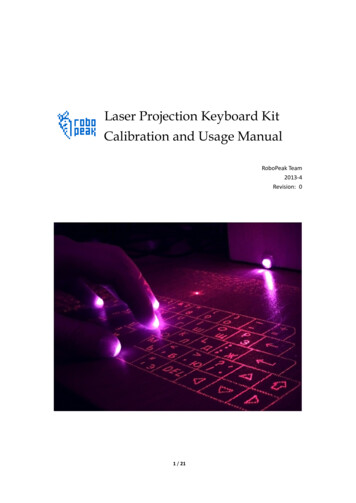
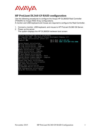
WIRING DIAGRAMConnecting Keyboard Controller and Connector Box.12345678DC12V AdaptorRJ-45 Cable182736PTZ(Fast Dome Camera)Twin Pair CableDVRLink Keyboard4Twin Pair Cable5Twin Pair CableRJ-45 and Connector Box Pin Assignment.12345678TerminalRJ-45Name1DC 12V input2GND3RS-485 DVR4RS-485 -DVR18275RS-485 OUTLink Keyboard366RS-485 - OUTLink Keyboard457RS-485 INPTZ or Matrix8RS-485 - INPTZ or MatrixConnector BoxPRODUCT COMPONENTSKeyboard ControllerConnector BoxPower AdaptorUser's Instruction ManualKeyboard ControllerPIH-931D/932TINSTRUCTION MANUAL16RJ-45 Connection Cable
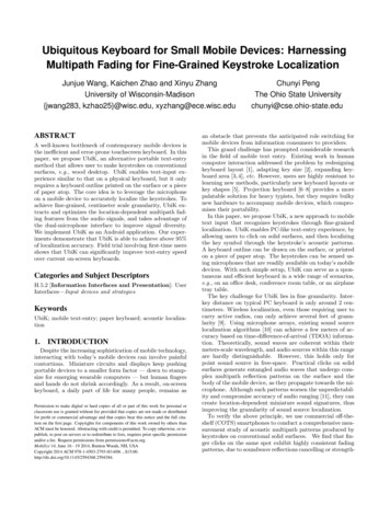
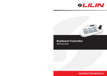
SYSTEM OVERVIEWPTZ (Fast Dome Camera) System BlockRS-485POWERPOWER06/02/15 12 00 00PTZ MODE ID 000ALARMALARMR/TPOWER06/02/15 12 00 00PTZ MODE ID 000ALARMR/TKeyboard 8(ID 8)06/02/15 12 00 00PTZ MODE ID 000R/TKeyboard 2(ID 2)Keyboard 1(ID 1)CAM 1CAM 2CAM 256Matrix System BlockRS-485VIDEOCAM 1CAM 2CAM 64VIDEOMATRIXPIH-864MATRIXRS-485POWERPOWER06/02/15 12 00 00PTZ MODE ID 000ALARMPOWER06/02/15 12 00 00PTZ MODE ID 000ALARMR/TKeyboard 106/02/15 12 00 00PTZ MODE ID 000ALARMR/TMonitor 1R/TKeyboard 2Monitor 2Monitor 16Keyboard 8DVR System BlockRS-485CAM 1VIDEORS-485CAM 16JOGBACKUPSHUTTLEREWMENUESCFFCAM 1VIDEORS-4859210311412513CAM 16JOGBACKUPREWMENUESCREC1RS-485CAM 1VIDEORS-485SHUTTLEFFJOGBACKUP7815161RECHDDAL9USB POWERVIDEODVR 1210311541213SHUTTLEFFREC6781415161RECHDDAL29USB POWERVIDEODVR 2Monitor 1REWMENUESCREC614CAM 16Monitor 210311412513678141516RECHDDALUSB POWERVIDEODVR 16Monitor 16RS-485POWERALARM06/02/15 12 00 00PTZ MODE ID 000R/TPOWERALARM06/02/15 12 00 00PTZ MODE ID 000R/TPOWERALARMPOWER06/02/15 12 00 00PTZ MODE ID 000ALARMR/T06/02/15 12 00 00PTZ MODE ID 000R/TRS-485VIDEOKeyboard 1(ID 1)Keyboard 2(ID 2)Keyboard 3(ID 3)17Keyboard 4(ID 4)
PTZ (Fast Dome Camera) System DO TXDITXDI (24Vac90 CADAPTORPOWERADAPTORPOWER06/02/15 12 00 00PTZ MODE ID 000ALARMPOWER06/02/15 12 00 00PTZ MODE ID 000ALARMR/T06/02/15 12 00 00PTZ MODE ID 000ALARMR/TR/TACACKeyboard 1Keyboard 2Keyboard 8Matrix and PTZ (Fast Dome Camera) System WiringRS-485PCGNDTXDOTXDO TXDITXDI 323742475257TXDOUT TXDIN GND--12V 1462TXDO TXDO-CAMALARM IN 451015202530354045505560ALARM IN BKEY BOARD371115481216RS232RECEIVERAC INAUX 2-4V-9VVIDEO OUTAUX 1WIPERVIDEO 45230 (117) VReceiverL NEL NEACINPUTL NEL NEACACOUTPUT 1 OUTPUT 2POWERALARMR/TKeyboardController1806/02/15 12 00 00PTZ MODE ID 000POWERALARM06/02/15 12 00 00PTZ MODE ID 000R/TKeyboardController
DVR and PTZ (Fast Dome Camera) System WiringWith one keyboard 1910)311CAMERA IN5412136147151GNDTXDOTXDO TXDITXDI (24Vac90 260Vac28AUDIO AN1AC 100 240V8POWER06/02/15 12 00 00PTZ MODE ID 000ALARMR/TRJ-45MonitorKeyboardWith muti-keyboard 19)103111CAMCAMERA IN541213614715816AUDIO INVIDEOOUTS-VIDEO1324POWERALARM/RS485AUDIOOUTLANAC 100 240V16GNDTXDOTXDO TXDITXDI (24Vac90 2727363636454545ADAPTORACPOWERALARMADAPTOR06/02/15 12 00 00PTZ MODE ID 000POWERALARMR/TADAPTOR06/02/15 12 00 00PTZ MODE ID 00006/02/15 12 00 00PTZ MODE ID 000R/TACKeyboard 1POWERALARMR/TACKeyboard 219Keyboard 466-931CSE-4
Keyboard ControllerPIH-931D/932TMERIT LI-LIN ENT. CO., LTDhttp://www.meritlilin.com66-931CSEINSTRUCTION MANUAL
Press SHIFT SET button to activate the Keyboard system setup menu. Tilt the joystick up or down to select the menu setup page. Press the 1 11 button to set the number of the desired sub setup item. Press the ESC button to exit the sub setup item or keyboard system setup menu. MENU SETUP 1/4 1. KEYBOARD ID 2. SYSTEM MODE 3. PROTOCOL MENU SETUP .