Transcription
What’s in this user guide?Getting startedConnecting the cameraMaking your own cablesRemote controlContact informationUser GuideTANDBERG PrecisionHD 1080pCameraThank you for choosing TANDBERG!Your TANDBERG PrecisionHD 1080p Camerahas been designed to give you many years ofsafe, reliable operation.This user guide has been divided into severalchapters, all of which provide differentinformation. You can access the chaptersdirectly by clicking on the menu bar at the topof this page.You will find that some places informationhas been copied from other chapters (butadapted, when needed) to let you have allthe relevant information there and then. Thishelps eliminating the need to read through longsections before you can even think of gettingstarted.Our main objective with this user guide was toaddress your goals and needs. Please let usknow how well we succeeded!www.tandberg.comD14245.04—DECEMBER 20081
PrecisionHD 1080p CameraWhat’s in this user guide?Getting startedUser GuideConnecting the cameraMaking your own cablesRemote controlContact informationGetting startedThe camera at a glance. 4HDMI and HD-SDI. 4Cable lengths . . 4Cascaded cameras. 4Best view (face recognition). 5Using Best View. 5Connecting the cameraConnecting the camera. 7DIP switch settings for video output formats. 8Line voltage frequency. 8Cameras in daisy chain. 9Cascaded cameras. 9Making your own cablesMaking your own cables. 11What’sin thisuser guide?D14245.04—DECEMBER 2008INTELLECTUAL PROPERTY RIGHTSThe TANDBERG PrecisionHD 1080p camera covered by thisUser Guide is protected under copyright, patent, and otherintellectual property rights of various jurisdictions.Copyright TANDBERG 2008. All rights reserved.This User Guide may be reproduced in its entirety, includingall copyright and intellectual property notices, in limitedquantities in connection with the use of the Product.Except for the limited exception set forth in the previoussentence, no part of this User Guide may be reproduced,stored in a retrieval system, or transmitted, in any form, or byany means, electronically, mechanically, by photocopying,or otherwise, without the prior written permission ofTANDBERG. Requests for such permission should beaddressed to tandberg@tandberg.com.Controlling cameras from remoteInterfacing to the camera using the VISCA protocol. 13RS232 Parameters. 13RS232 Commands and inquiries. 13VISCA messages. 13Message Format. 13Network and interface commands. 14Video mode selection. 19Method. 19DIP Switch. 19DISCLAIMERThe specifications for the Product and the information in thisdocument are subject to change at any time, without notice,by TANDBERG.Every effort has been made to supply complete and accurateinformation in this User Guide. However, TANDBERGassumes no responsibility or liability for any errors orinaccuracies that may appear in this document.2
PrecisionHD 1080p CameraWhat’s in this user guide?Getting startedUser GuideConnecting the cameraMaking your own cablesRemote controlContact informationChapter 2Getting startedwww.tandberg.comD14245.04—DECEMBER 20083
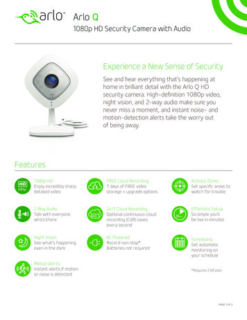
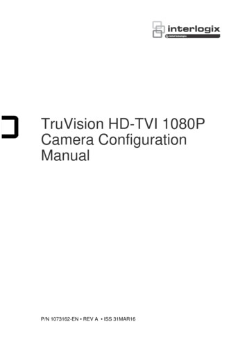
PrecisionHD 1080p CameraWhat’s in this user guide?Getting startedUser GuideConnecting the cameraMaking your own cablesRemote controlContact informationThe camera at a glanceVideo out (HDMI, HD-SDI). For video signals, connect from thevideo out on the camera to the video in on the codec.Power and camera control. For power in and camera control,connect from the camera control & power on the camera tothe Camera port on the codec. When the camera is used withTANDBERG codecs power will be supplied through Camera Controlcable. When used with non-TANDBERG codecs, you may have toconnect power separately.The orange LED illuminates whilst in acall and blinks whenever there isan incoming call.The lens hood is detachable.We recommend that youmount it to prevent stray lightfrom disturbing your videoexperience.HDMI and HD-SDI HDMI is the main source for video out when connected to acodec. Maximum resolution is 1080p60. HD-SDI is the secondary source for video. Maximum resolution is1080p30 (maximum recommendable cable length is then 100 m). The HDMI and HD-SDI can be used simultaneously. Themaximum resolution is then 1080p30 if you want both to run withthe same resolution.Cable lengthsMaximum length of HDMI cable is 15 meter with a category 2certified good quality HDMI cable.Just snap it on gently.Thegreen LEDis continuouslyilluminated when poweris On, but it flickers whenreceiving signals fromthe remote control.The maximum recommendable length of HD SDI cable is 100 m.Cascaded camerasHDMI and HD-SDI can beused simultaneously.The sockets named Extra Camera Out and Power In are used whenconnecting cameras in daisy chain. The first camera in the chain is powered up by the cameracontrol cable. The next cameras must use the 12V DC Power in. The daisy chained cameras are connected by using an extracamera cable between the Extra Camera sockets.Power SupplyCamera ControlExtra Camera Out and for Daisy ChainingD14245.04—DECEMBER 2008Not UsedHDMI Video OutHD-SDI Out4
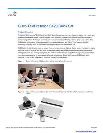
PrecisionHD 1080p CameraWhat’s in this user guide?Getting startedUser GuideConnecting the cameraMaking your own cablesRemote controlContact informationBest view (face recognition)This camera is capable of face recognition when used withTANDBERG C90 Codecs. Observe that the feature is still a previewfeature. Consequently, the functionality is subject to change withoutfurther notice in order to take advantage of further developments.The face recognition system aims to search for faces in order tooptimize the picture frame, hence the name Best View. Once a faceor group of faces has been detected camera zoom and camera anglewill be changed accordingly to obtain an optimal presentation on thescreen.Kindly observe the following: The Best View optimization process may take up to 5 seconds. The detection of faces works better when people look towards thecamera. The area from the eyebrows down to just below the lips should beuncovered. Beard is normally not a problem.Using Best ViewPress the correspondingSoft key to engage theBest View feature.Note that Best View works with TANDBERG C90 Codecs only!1. On the TRC5 remote control press the Home key to produce themain menu, if needed.2. Navigate down to Settings, then press the Right arrow keyproduce the submenu and press again to produce the Layoutsubmenu.3. Select Selfview to be shown as required.4. Press Home to collapse the menus5. Navigate to Camera control and press the Right arrow key.The soft keys menu will now be displayed as shown to the right.6. Press the corresponding key on the remote control to start theBest View function.The system will now look for human faces and adjust the zoom andcamera angle to obtain a best fit.D14245.04—DECEMBER 20081 .@2 abc4 ghi5 jkl7 pqrsdef3mno68 tuvwxyz 90abc/123#5
PrecisionHD 1080p CameraWhat’s in this user guide?Getting startedUser GuideConnecting the cameraMaking your own cablesRemote controlContact informationChapter 3Connecting the camerawww.tandberg.comD14245.04—DECEMBER 20086
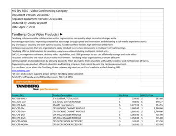
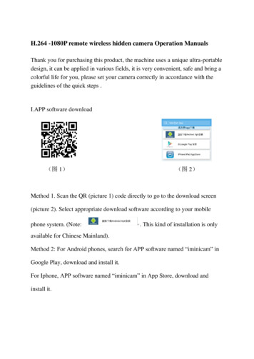
PrecisionHD 1080p CameraWhat’s in this user guide?Getting startedUser GuideConnecting the cameraMaking your own cablesRemote controlContact informationConnecting the cameraThe HDMI and HD-SDI can be usedsimultaneously.HDMI cableThe HDMI cable delivered with the camera is5 meters. Maximum length is 15 meter with acategory 2 certified good quality HDMI cable.HD-SDI cableThe HD-SDI cable must be purchasedseparately.HDMI to DVI-D adapterHD-SDI socketThe HDMI to DVI-D adapter is used whenconnecting to a TANDBERG MXP codec orTANDBERG Video SwitchHDMI and HD-SDIcan be used simultaneously.Power supply connectionis NOT needed when thecamera is used with aTANDBERG Codec.Camera Control. RJ45 to RS 232.Visca protocol is supported.Line inConnect HDMI HD Video out on camera to HDMI Main Camera In on the Codec.If you need to connect the camera to a TANDBERG Video Switch or to a system with a DVI-D socket, usethe enclosed HDMI to DVI-D adapter.VISCA is a trademark of Sony CorporationD14245.04—DECEMBER 20087
PrecisionHD 1080p CameraWhat’s in this user guide?Getting startedUser GuideConnecting the cameraMaking your own cablesContact informationRemote controlVideo output formatsThis section describes the video output formats for the TANDBERGPrecisionHD 1080p camera.DIP switch settings for video output formatsThe video output format for the camera is set by DIP switches. TheDIP switches are found on the bottom side of the camera.DIP Switch table for video 1080p30000111080p50720p50001001080p60720p60Line voltage frequency00101720p25720p25The camera will automatically detect the line voltage frequency when itis 50 or 60 Hz. You may set the video output format to a specific value(use the DIP switches) to override the auto frequency detection, if adifferent line voltage frequency is an 0720p6001001The default setting is Auto. When using HDMI, the video output formatis automatically detected. See the table to the right.Maximum resolution for HDMI is 1080p60.Maximum resolution for HD-SDI is 1080p30.Note that the camera must be switched off and on again to make thenew DIP switch settings effective.The DIP switchHDMIHD-SDIAutoSoftware controlThe table shows the different settings available for the HDMIand the HD-SDI outputs.Auto: Camera negotiates format over HDMI. HD-SDI tracksHDMI and defaults to 1080p30 in absence of HDMI sync.Software: For more on the Software control setting, seeVideo mode selection.D14245.04—DECEMBER 20088
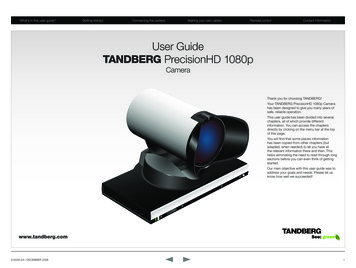
PrecisionHD 1080p CameraWhat’s in this user guide?Getting startedUser GuideConnecting the cameraMaking your own cablesContact informationRemote controlCameras in daisy chainA single daisy chain can have up to sevencameras.Cascaded camerasThe sockets named Extra Camera and PowerIn are used when connecting cameras in daisychain. HDMI and HD-SDI. The HDMI and HD-SDIcan be used simultaneously on the samecamera. Power. The first camera in the chain ispowered up from the codec by the VISCAcamera control cable. Additional camerasmust use the 12V DC Power in. Extra camera cable. The daisy chainedcameras are connected by using theVISCA Extra Camera cable between theExtra Camera In and Codec Control InsocketsD14245.04—DECEMBER 2008RJ11–RJ45Connect to theCamera Controlsocket on theCodec. When usedwith TANDBERGCodecs, this firstcamera will needno power supplyconnected.12 VdcConnect to Video Input 1on Codec.12 VdcRJ11–RJ45Connect to Video Input 2on Codec.RJ11–RJ4512 VdcConnect to Video Input 3on Codec.Connect to Video Input 4 onCodec.9
PrecisionHD 1080p CameraWhat’s in this user guide?Getting startedUser GuideConnecting the cameraMaking your own cablesRemote controlContact informationChapter 4Making your own cableswww.tandberg.comD14245.04—DECEMBER 200810
PrecisionHD 1080p CameraWhat’s in this user guide?User GuideGetting startedMaking your own cablesConnecting the cameraRemote controlContact informationMaking your own cablesIf you need to assemble your own cables, thetables to the right show the pin-out required.Pin-out—TANDBERG camera cableRJ45 (8 pin) to D-SUBSignalnameRJ45pinD-SUBpin 12Vdc1GND2Twistedpair4RX3TX6NC4NC5GND7 12Vdc8Pin-out—VISCA Camera controlRJ 45 8 pins shielded modular jackPinSignal name8 12V (2.8mA current source whenconnected in daisy chain)57GNDTwistedpair26TXD (out)35NC (no connect)Twistedpair14NC (no connect)63RXD (in)52GND41 12VTwistedpairPin-out—VISCA Daisy chainPinD14245.04—DECEMBER 2008RJ 11 6 pins modular jackSignal name6GND5GND4RXD (in)3TXD (out)2Presence (12V in daisy chain)1GND11
PrecisionHD 1080p CameraWhat’s in this user guide?Getting startedUser GuideConnecting the cameraMaking your own cablesRemote controlContact informationChapter 5Controlling cameras from remotewww.tandberg.comD14245.04—DECEMBER 200812
PrecisionHD 1080p CameraWhat’s in this user guide?Getting startedInterfacing to the camera usingthe VISCA protocolUser GuideConnecting the cameraMaking your own cablesRemote controlCommand and response exchangeThe RS232 Message formatWhen the camera receives a command, itresponds with either:The TANDBERG PrecisionHD 1080p camera usesan RS-232 control interface that resembles theSony VISCA protocol. Completion message: 90-5Y-FFReturned by camera when execution ofcommands and inquiries are completed. Error packets: 90-6Y-.-FFReturned by camera instead of a completionmessage when command or inquiry failed to beexecuted.RS232 Parameters.At startup, the communication parameters for theRS232 interface must be set to: 9600 bits per second8 databitsNo parity1 stopbitNo hardware flow controlNo software flow controlAll parameters except speed are fixed and notuser configurable. The speed may be changedby issuing the Speed command defined on thefollowing pages. All control bytes are pure binaryinformation, i.e. the control bytes are not ASCIIencoded.RS232 Commands and inquiriesA list of all the available commands and inquiriestogether with the result and comments are found inthe table on the following pages.General error messages, unless otherwisespecified: VISCA messagesA particular command is recognized by themessage information after the address byte.Message FormatCommands are initiated from the host (i.e. thecodec or any other external controller) to thecamera.After a camera has been issued a command, thecamera will generate a response. Commands andresponses (messages) have the following format: Address byte (1)Information bytes (1.14)Terminating byte (1)See the above illustration for details.Contact informationThe minimum length of any command orresponse is 3 bytes:1. Address byte (1): Let us assume there isone host, i.e. the codec (the host is the unitcontrolling the camera). The host has address0. The four least significant bits of the addressbyte contain the address of the receiver. In thecase of a broadcast message, the receiveraddress should be set to 8. When we areoperating a single camera, the address is 1.Hence, address bytes in messages from thehost are 0x81, and messages from the camerato the host are 0x90 (the protocol allows for upto 7 cameras).2. Message bytes (1.14): Any number of bytescontaining the actual message information.Bytes may have any value in the range 0.254.The value 255 (i.e. hexadecimal FF) is reservedfor the terminating byte. 90-6Y-01-FF Message length error( 14 bytes) 90-6Y-02-FF Syntax error 90-6Y-03-FF Command buffer full 90-6Y-04-FF Command cancelled 90-6Y-05-FF No socket (to be cancelled) 90-6Y-41-FF Command not executableY socket numberA camera may contain two buffers so that twocommands, including the command beingexecuted, can be received.Note: The PrecisionHD 1080p camerasupports a single socket only. Consequently,the Y always assumes the value Y 0.There are exceptions to these rules: An Initialize message will respond as indicatedin the Table of Commands (this message is infact a broadcast message, and any unit otherthan the host receiving the broadcast messagemust pass it on). Do not route commands or replies that arelonger than 16 bytes through Sony cameras.The easiest way to avoid this is to put theTANDBERG cameras first in the chain.Commands and replies that are longer than 16bytes are clearly marked below.3. Terminating byte (1): All messages must beterminated with a byte containing all 1’s, i.e.decimal 255 (or hexadecimal FF).D14245.04—DECEMBER 200813
PrecisionHD 1080p CameraWhat’s in this user guide?Getting startedUser GuideConnecting the cameraNetwork and interface commandsRemote controlMaking your own cablesContact informationPush messagesMessages sent from camera to controller.Command SetCommand PacketCommentsCommand SetCommand PacketReply and CommentsIF Clear8x 01 00 01 ffClear command buffer. Stopany current operation inprogress. Does not do muchon Rover.Network Changey0 38 ffThis indicates that camerashave been added to orremoved from the chain.Address Set8x 30 0p ffp address for this device. Ifx 8 (broadcast), increase pwith 1 before sending to chain.Command Cancel8x 2p ffp Socket ID. Rover doesnot support multiple sockets.Commands will always run tocompletion. Don’t use itIt is recommended to wait 9seconds after receiving thismessage before doing a fullreconfigure.IR Pushy0 07 7d 02 gg hh ffIf IR mode is on, IR codesreceived by the camera will besent to the controller.gg IR IDhh keycodeBestView Done Pushy0 0a 61 0p 0q ffFirst push message sent afterBestView is done.pq Number of framesdetected. The camera willgenerate pq Res Pushmessages after this message.BestView Res Pushy0 0a 62 0p 0q [tiltpos] [panpos][tiltSize] [panSize] [yPos] [xPos][yDim] [xDim] [trackDur] [quality][speech] ffpq Face number, should beless than or equal to pq given inDone Push.Parameters specified inbrackets are unsigned 16 bitquantities, defined as “0p 0q0r 0s”.[tiltpos] and [panpos] are 16 bitsigned.Make sure this message is notrouted through Sony cameras.D14245.04—DECEMBER 200814
PrecisionHD 1080p CameraWhat’s in this user guide?Getting startedUser GuideConnecting the cameraMaking your own cablesRemote controlContact informationCamera commandsCommandCommand PacketCommentsPower On8x 01 04 00 02 ffPower Off8x 01 04 00 03 ffPower control. This commandstores the zoom and focusvalue and reset these motors.Used for Tiger if the camerawas on for a long time.Video FormatWB Auto8x 01 35 0p 0q 0r ff8x 01 04 35 00 FFSelects video format. p reserved. q video mode. r See the chapter about the DIPswitch settingsWB: White BalanceWB Table Manual8x 01 04 35 06 ffWB Table Direct8x 01 04 75 0p 0q 0r 0s ffUsed if WBmode Tablemanual pqrs wb table.AE Auto8x 01 04 39 00 FFAE: Automatic Exposure.AE Manual8x 01 04 39 03 FFIris Direct8x 01 04 4B 0p 0q 0r 0s FFUsed if AE mode Manual.pqrs: Iris position, range 0.50Gain Direct8x 01 04 4c 0p 0q 0r 0s FFUsed if AE mode Manual.pqrs: Gain position, values:1221dB.Backlight On8x 01 04 33 02 FFBacklightCompensation modeBacklight Off8x 01 04 33 03 FFMirror On8x 01 04 61 02 ffMirror Off8x 01 04 61 03 ffFlip On8x 01 04 66 02 ffFlip Off8x 01 04 66 03 ffCommand PacketCommentsRefers to orange LED on topof camera. Will always be offat startup.Call LED On8x 01 33 01 01 ffCall LED Off8x 01 33 01 00 ffCall LED Blink8x 01 33 01 02 ffPower LED On8x 01 33 02 01 ffPower LED Off8x 01 33 02 00 ffIR Output On8x 01 06 08 02 ffIR Output Off8x 01 06 08 03 ffIR CameraControl On8x 01 06 09 02 ffIR CameraControl Off8x 01 06 09 03 ffBestView On8x 01 50 60 0p 0q ffBestView Stop8x 01 50 60 00 00 ffGreen power LED. If switchedto off and stored to startupprofile, it will always be off.See IR push message.Lets up/down/left/right/zoom /- on the IR remotecontrol the camera directly.Those keycodes will be sent tothe controller if IR Output is on.Turn BestView on or off.pq time (in seconds) Willgenerate push message(s) asspecified above when the timeruns out.Sony calls this CAM LRReverse. RR (FT/AT mirrorcommand)Sony calls this CAM ImgFlip.Gamma Auto8x 01 04 51 02 ffGamma Manual8x 01 04 51 03 ffGamma Direct8x 01 04 52 0p 0q 0r 0s ffpqrs: Gamma table to use inmanual mode. Range 0-7.MM Detect On8x 01 50 30 01 ffTurn on the Motor MovedDetection (camera recalibratesif touched)MM Detect Off8x 01 50 30 00 ffTurn off the Motor MovedDetection (camera does notrecalibrate if touched)D14245.04—DECEMBER 2008CommandGamma mode. Default usesgamma table 4.15
PrecisionHD 1080p CameraWhat’s in this user guide?Getting startedUser GuideConnecting the cameraMaking your own cablesRemote controlContact informationPTZF - movement commandsCommandCommand PacketCommentsZoom Stop8x 01 04 07 00 ffZoom Tele8x 01 04 07 2p ffZoom Wide8x 01 04 07 3p ffZoom Direct8x 01 04 47 0p 0q 0r 0s ffpqrs: zoom positionZoomFocus Direct8x 01 04 47 0p 0q 0rpqrs: zoom position0stuvw: focus positionCommandCommand PacketCommentsPT Direct8x 01 06 02 0p 0t 0q 0r 0s 0u0v 0w 0x 0y FFp: max pan speedt: max tilt speedqrsu: pan positionvwxy: tilt positionp speed parameter,a (low) to b (high)Attempts to linearize movement.PTZF Direct8x 01 06 20 0p 0q 0r 0s 0t 0u0v 0w 0x 0y 0z 0g 0h 0i 0j 0k ffpqrs: pantuvw: tiltxyzg: zoomhijk: focus0t 0u 0v 0w ffFocus Stop8x 01 04 08 00 ffFocus Far8x 01 04 08 2p ffFocus Near8x 01 04 08 3p ffFocus Direct8x 01 04 48 0p 0q 0r 0s ffpqrs: focus positionFocus Auto8x 01 04 38 02 ffAutofocus mode on/off.p speed parameter,a (low) to b (high)NOTE: If mode is auto, cameramay disable autofocus whenfocus is ok. Autofocus will beturned back on when camerais moved using Zoom Tele/Wide, PT Up/Down/Left/Right.Ditto for IR CameraControlmovement.Never route this messagethrough Sony cameras.Attempts to linearize movementfor pan and tiltPT Limit Set8x 01 06 07 00 0x 0p 0q 0r 0s0t 0u 0v 0w ffx 1: Up/Rightx 0: Down/Leftpqrs: Pan limittuvx: Tilt limit.This command is valid only tonext boot.PT Limit Clear8x 01 06 07 01 0x [.] ffx 1: Up/Rightx 0: Down/LeftSony specifies lots of filler bytesafter 0x. Ignore them.Focus Manual8x 01 04 38 03 ffPT Stop8x 01 06 01 03 03 03 03 ffPT Reset8x 01 06 05 ffReset pan/tilt to centerpositition. Will alsoresynchronize motors.PT Up8x 01 06 01 0p 0t 03 01 ffPT Down8x 01 06 01 0p 0t 03 02 ffp pan speedt: tilt speedPT Left8x 01 06 01 0p 0t 01 03 ffPT Right8x 01 06 01 0p 0t 02 03 ffPT UpLeft8x 01 06 01 0p 0t 01 01 ffPT UpRight8x 01 06 01 0p 0t 02 01 ffPT DownLeft8x 01 06 01 0p 0t 01 02 ffPT DownRight8x 01 06 01 0p 0t 02 02 ffD14245.04—DECEMBER 2008Sets all motors in oneoperation.Right - increment panLeft - decrement panUp - increment tiltDown - decrement tilt16
PrecisionHD 1080p CameraWhat’s in this user guide?Getting startedUser GuideConnecting the cameraMaking your own cablesRemote controlContact informationInquiriesCommandCommand PacketResponseCommandCommand PacketResponseCAM ID Inq8x 09 04 22 ffResp: 90 50 zz xx 00 yy ffOnly zz, which identifies thecamera, is relevant. zz 0x50for this camera.Gamma Table Inq8x 09 04 52 ffResp: y0 50 0p 0q 0r 0s ffpqrs: Gamma table in use ifmanual mode.Call LED Inq8x 09 01 33 01 ffCAM SWID Inq8x 09 04 23 ffResp: y0 50 [1-125 bytes ASCIISWID] ff. Never route thismessage through Sony cameras.Resp: y0 50 0p ffp 2: On, p 3: Off, p 4: BlinkPower LED Inq8x 09 01 33 02 ffResp: y0 50 0p ffp 2: On, p 3: OffVideo System Inq8x 09 06 23 ffy0 50 0p 0q 0r 0s ffpqrs video mode currentlybeing output on the HDMI port.See chapter on DIP switches.DIP Switch Inq8x 09 06 24 ffy0 50 0p 0q 0r 0s ff pqrscontains the bit pattern of theDIP switch. See chapter on DIPswitches.IR Output Inq8x 09 06 08 ffResp: y0 50 0p ffp 2: On, p 3: OffALS RGain Inq8x 09 50 50 ffAmbient Light Sensor Resp: y050 0p 0q 0r 0s 0t 0u 0v 0w ffCAM HWID Inq8x 09 04 24 ffThe response is the ModuleSerial Number stored inEEPROM. The number isconverted to ASCII : y0 50 [12bytes ASCII HWID] ff.Zoom Pos Inq8x 09 04 47 ffResp: y0 50 0p 0q 0r 0s ffpqrs: zoom positionFocus Pos Inq8x 09 04 48 ffResp: y0 50 0p 0q 0r 0s ffpqrs: focus positionFocus Mode Inq8x 09 04 38 ffResp: y0 50 0p ffp 2: Auto, p 3: ManualPanTilt Pos Inq8x 09 06 12 ffResp: y0 50 0p 0q 0r 0s 0t 0u0v 0w ffpqrs: pan position tuvw:tilt positionpqrstuv 32 bit unsignedinteger, relative gain value. Theintegration time is a constantset in the camera SW.Power Inq8x 09 04 00 ffResp: y0 50 0p ffp 2: On, p 3: OffALS BGain Inq8x 09 50 51 ffWB Mode Inq8x 09 04 35 ffResp: y0 50 0p ffp 0: Auto , p 6: Table manualALS GGain Inq8x 09 50 52 ffWB Table Inq8x 09 04 75 ffResp: y0 50 0p 0q 0r 0s ffpqrs: Table used if table modeALS WGain Inq8x 09 50 53 ffBestView Inq8x 09 50 60 ffAE Mode Inq8x 09 04 39 ffResp: y0 50 0p ffp 0: Auto, p 3: ManualBacklight Mode Inq8x 09 04 33 ffResp: y0 50 0p ffp 2: On, p 3: OffResp: y0 50 0p 0q 0r 0s ffpq 0: BestView not running.pq 0: BestView running, timespecified when startedrs: Time spent so farUp side down Inq8x 09 50 70 ffMirror Inq8x 09 04 61 ffResp: y0 50 0p ffp 2: On, p 3: OffResp: y0 50 0p ffp 0: Camera is upright.p 1: Camera is upside down.Flip Inq8x 09 04 66 ffIs video flipped or not?Resp: y0 50 0p ffp 2: On , p 3: OffGamma Mode Inq8x 09 04 51 ffResp: y0 50 0p ffp 2: Auto, p 3: ManualD14245.04—DECEMBER 200817
PrecisionHD 1080p CameraWhat’s in this user guide?Getting startedUser GuideConnecting the cameraRemote controlMaking your own cablesContact informationSoftware upload commandsDebug commandsThe CRC algorithm used is the same as in the XModem protocol. CRC for last data packet is only calculatedfor the actual data bytes in the packet. Pad last packet with 0x00 so that the data section is 256 bytes long.Never route these messages through Sony cameras. They are provided for Rover debugging only, and donot conform to the Visca length requirements.The PacketID counter starts at 0.CommandCommand PacketCommentsCommandCommand PacketCommentsSW start8x 01 50 a2 0p 0q 0r 0s 0t 0u0v 0w ffpqrstuvw size, pq LSBReturns y050ff if ok.CAM PingPong Reset8x ae ffReset ping ctr to 0.CAM Ping8x af 0p 0q 0r 0s [256 bytesdata] ffpqrs Pingval. Camera willrespond with OK if correctpingval received. Increase ctrwith 1 for next packet. Datasection will be dumped tostdout if it fails.CAM Stdin8x a4 [0-256 bytes stdin] 00 ffSend command to thecommand interpreter.CAM Debug Mode8x 01 39 0q ffq 0: Debug mode off.Fatal errors: Returns y06006ffif upload already in progress.Returns y06007ff if unable toaccess the flash.SW end8x 01 50 a1 ffSent after last SW packet,instructs camera to verifynew application. Commandmay take up to 30 seconds tocomplete.q 1: Debug mode on. Camerawill send stdout as viscamessages in the followingformat:Returns y050ff if ok. Issue acamera reboot to activate newsoftware.Returns y06008ff if verificationof sw failed.SW abort8x 01 50 a3 ffAbort sw upload in progressSW packet8x a0 pp qq rr ss [256 bytesdata]ppqq 16 bit packet id,pp LSBrrss 16 bit CRC, rr LSBy0 50 [0-256 bytes stdout] 00 ffOther commandsCommandCommand PacketCommentsReturns y0 50 ff if packet ok.- send next one.CAM Boot8x 01 42 ffReboot the camera. This willalso reset serial speed to 9600.Returns y0 60 09 ff if crc error- retransmit packet.CAM Speed8x 01 34 0p ffp 0: Serial speed 9600. p 1:Serial speed 115200. Reply willbe sent before the speed switchtakes place. Please wait 20msafter ok before sending newcommands.Returns y0 60 0a ff if id error- retransmit packetFatal errors:y0 60 0b ff not in upload modey0 60 0c ff error writing datato flashNOTE: Entire message after8x a0. is raw data, so it maycontain 0xff. Header is kept asshort as possible. Never routethis message through Sonycameras.D14245.04—DECEMBER 200818
PrecisionHD 1080p CameraWhat’s in this user guide?Getting startedUser GuideConnecting the cameraContact informationRemote controlMaking your own cablesVideo mode selectionMethodThe DIP switch selection has priority over the selection made bythe CAM Video Format command. If the DIP switch is set to auto,the CAM Video Format setting will be used. If both are set to auto,resolution will be controlled automatically by EDID.DIP SwitchSwitches are numbered 1 to 5. The VISCA column shows the valuethat should be used when using the CAM Video Format command.The DIP switches are only read by the SW at startup/boot. So if theDIP switches are changed the camera must be rebooted.If an undefined mode is selected, the output will default to p50010000x0007720p60720p60010010x0009SW control* Camera negotiates format over HDMI, HD-SDI tracks HDMI, and defaults to 1080p30 inabsence of HDMI sync.10The DIP switchD14245.04—DECEMBER 200819
PrecisionHD 1080p CameraWhat’s in this user guide?Getting startedUser GuideConnecting the cameraU.S. HEADQUARTERSTANDBERG1212 Avenue of the Americas24th FloorNew York, NY 10036Telephone: 1 212 692 6500Fax: 1 212 692 6501Video: 1 212 692 6535E-mail: tandberg@tandberg.comMaking your own cablesRemote controlContact informationEUROPEAN HEADQUARTERSTANDBERGPhilip Pedersens vei 201366 LysakerNorwayTelephone: 47 67 125 125Fax: 47 67 125 234Video: 47 67 126 126E-mail: tandberg@tandberg.comCopyright TANDBERG 2008. All rights reserved.This document contains information that is proprietary to TANDBERG. No part of this publicationmay be reproduced, stored in a retrieval system, or transmitted, in any form, or by any means,electronically, mechanically, by photocopying, or otherwise, without the prior written permissionof TANDBERG. Nationally and internationally recognized trademarks and trade names are theproperty of their respective holders and are hereby acknowledged.D14245.04—DECEMBER 200820
Video mode selection. The DIP switch 1 0 Video output formats This section describes the video output formats for the TANDBERG PrecisionHD 1080p camera. DIP switch settings for video output formats The video output format for the camera is set by DIP switches. The DIP switches are found on the bottom side of the camera. The default setting is Auto.