Transcription
Second Ed itionDataNetworksDIMITRI BERTSEKASMassachusetts Institute of TechnologyROBERT GALLAGERMassachusetts Institute of TechnologyPRENTICE HALL,Englewood Cliffs, New Jersey 07632
2Node ATime at B ---------Node BPacket 0Point-to-PointProtocols and Links2.1 INTRODUCTIONThis chapter first provides an introduction to the physical communication links thatconstitute the building blocks of data networks. The major focus of the chapter isthen data link control (i.e., the point-to-point protocols needed to control the passageof data over a communication link). Finally, a number of point-to-point protocols atthe network, transport, and physical layers are discussed. There are many similaritiesbetween the point-to-point protocols at these different layers, and it is desirable to discussthem together before addressing the more complex network-wide protocols for routing,flow control, and multiaccess control.The treatment of physical links in Section 2.2 is a brief introduction to a very largetopic. The reason for the brevity is not that the subject lacks importance or inherentinterest, but rather, that a thorough understanding requires a background in linear systemtheory, random processes, and modem communication theory. In this section we provide a sufficient overview for those lacking this background and provide a review andperspective for those with more background.37
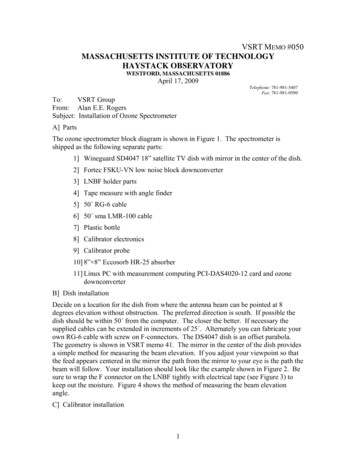
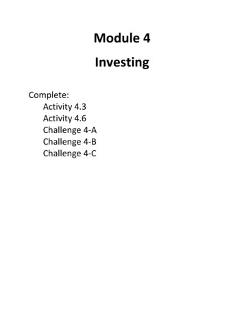
38Point-to-Point Protocols and LinksChap. 2In dealing with the physical layer in Section 2.2, we discuss both the actual communication channels used by the network and whatever interface modules are required atthe ends of the channels to transmit and receive digital data (see Fig 2.1). We refer tothese modules as modems (digital data modulators and demodulators), although in manycases no modulation or demodulation is required. In sending data, the modem convertsthe incoming binary data into a signal suitable for the channel. In receiving, the modemconverts the received signal back into binary data. To an extent, the combination of modem, physical link, modem can be ignored; one simply recognizes that the combinationappears to higher layers as a virtual bit pipe.There are several different types of virtual bit pipes that might be implementedby the physical layer. One is the synchronous bit pipe, where the sending side of thedata link control (DLC) module supplies bits to the sending side of the modem at asynchronous rate (i.e., one bit each T seconds for some fixed T). If the DLC moduletemporarily has no data to send, it must continue to send dummy bits, called idle fill,until it again has data. The receiving modem recovers these bits synchronously (withdelay and occasional errors) and releases the bits, including idle fill, to the correspondingDLC module.The intermittent synchronous bit pipe is another form of bit pipe in which thesending DLC module supplies bits synchronously to the modem when it has data tosend, but supplies nothing when it has no data. The sending modem sends no signalduring these idle intervals, and the receiving modem detects the idle intervals and releasesnothing to the receiving DLC module. This somewhat complicates the receiving modem,since it must distinguish between 0, 1, and idle in each time interval, and it must alsoregain synchronization at the end of an idle period. In Chapter 4 it will be seen that thecapability to transmit nothing is very important for multiaccess channels.A final form of virtual bit pipe is the asynchronous character pipe, where the bitswithin a character are sent at a fixed rate, but successive characters can be separated byPacketsFramesVirtual synchronous unreliable bit pipeCommunication linkFigure 2.1Data link control (DLC) layer with interfaces to adjacent layers.
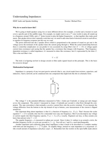
Sec. 2.1Introduction39variable delays, subject to a given minimum. As will be seen in the next section, this isused only when high data rates are not an important consideration.In Sections 2.3 to 2.7 we treat the DLC layer, which is the primary focus of thischapter. For each point-to-point link, there are two DLC peer modules, one module ateach end of the link. For traffic in a given direction, the sending DLC module receivespackets from the network layer module at that node. The peer DLC modules employa distributed algorithm, or protocol, to transfer these packets to the receiving DLC andthence to the network layer module at that node. In most cases, the objective is to deliverthe packets in the order of arrival, with neither repetitions nor errors. In accomplishingthis task, the DLC modules make use of the virtual bit pipe (with errors) provided bythe physical layer.One major problem in accomplishing the objective above is that of correcting thebit errors that occur on the virtual bit pipe. This objective is generally accomplishedby a technique called ARQ (automatic repeat request). In this technique, errors arefirst detected at the receiving DLC module and then repetitions are requested from thetransmitting DLC module. Both the detection of errors and the requests for retransmissionrequire a certain amount of control overhead to be communicated on the bit pipe. Thisoverhead is provided by adding a given number of bits (called a header) to the frontof each packet and adding an additional number of bits (called a trailer) to the rear(see Fig. 2.2). A packet, extended by this header and trailer, is called a frame. Fromthe standpoint of the DLC, a packet is simply a string of bits provided as a unit bythe network layer; examples arise later where single "packets," in this sense, from thenetwork layer contain pieces of information from many different sessions, but this makesno difference to the DLC layer.Section 2.3 treats the problem of error detection and shows how a set of redundant bits in the trailer can be used for error detection. Section 2.4 then deals withretransmission requests. This is not as easy as it appears, first because the requests mustbe embedded into the data traveling in the opposite direction, and second because theopposite direction is also subject to errors. This provides our first exposure to a realdistributed algorithm, which is of particular conceptual interest since it must operate inthe presence of errors.In Section 2.5 we discuss framing. The issue here is for the receiving DLC moduleto detect the beginning and end of each successive frame. For a synchronous bit pipe,the bits within a frame must contain the information to distinguish the end of the frame;also the idle fill between frames must be uniquely recognizable. This problem becomeseven more interesting in the presence of errors.A widely accepted standard of data link control is the HDLC protocol. This isdiscussed in Section 2.6, followed in Section 2.7 by a general discussion of how toinitialize and to disconnect DLC protocols. This topic might appear to be trivial, but oncloser inspection, it requires careful thought.1 .-----IHeaderFramePacket--------- · ITrailerIFigure 2.2 Frame structure. A packetfrom the network layer is extended in theDLC layer with control bits in front and inback of the packet.
40Point-to-Point Protocols and LinksChap. 2Section 2.8 then treats a number of network layer issues, starting with addressing.End-to-end error recovery, which can be done at either the network or transport layer, isdiscussed next, along with a general discussion of why error recovery should or shouldnot be done at more than one layer. The section ends with a discussion first of theX.25 network layer standard and next of the Internet Protocol (IP). IP was original1ydeveloped to connect the many local area networks in academic and research institutionsto the ARPANET and is now a defacto standard for the internet sublayer.A discussion of the transport layer is then presented in Section 2.9. This focuses onthe transport protocol, TCP, used on top of IP. The combined use of TCP and IP (usual1ycal1ed TCP/IP) gives us an opportunity to explore some of the practical consequences ofparticular choices of protocols.The chapter ends with an introduction to broadband integrated service data networks. In these networks, the physical layer is being implemented as a packet switchingnetwork called ATM, an abbreviation for "asynchronous transfer mode." It is interesting to compare how ATM performs its various functions with the traditional layers ofconventional data networks.2.2 THE PHYSICAL LAYER: CHANNELS AND MODEMSAs discussed in Section 2.1, the virtual channel seen by the data link control (DLC) layerhas the function of transporting bits or characters from the DLC module at one end ofthe link to the module at the other end (see Fig. 2.1). In this section we survey howcommunication channels can be used to accomplish this function. We focus on point-topoint channels (i.e., channels that connect just two nodes), and postpone consideration ofmultiaccess channels (i.e., channels connecting more than two nodes) to Chapter 4. Wealso focus on communication in one direction, thus ignoring any potential interferencebetween simultaneous transmission in both directions.There are two broad classes of point-to-point channels: digital channels and analogchannels. From a black box point of view, a digital channel is simply a bit pipe, with a bitstream as input and output. An analog channel, on the other hand, accepts a waveform(i.e., an arbitrary function of time) as input and produces a waveform as output. Wediscuss analog channels first since digital channels are usually implemented on top of anunderlying analog structure.A module is required at the input of an analog channel to map the digital datafrom the DLC module into the waveform sent over the channel. Similarly, a moduleis required at the receiver to map the received waveform back into digital data. Thesemodules wil1 be referred to as modems (digital data modulator and demodulator). Theterm modem is used broadly here, not necessarily implying any modulation but simplyreferring to the required mapping operations.Let set) denote the analog channel input as a function of time; set) could represent a.voltage or current waveform. Similarly, let ret) represent the voltage or current waveformat the output of the analog channel. The output ret) is a distorted, delayed, and attenuatedversion of set), and our objective is to gain some intuitive appreciation of how to map
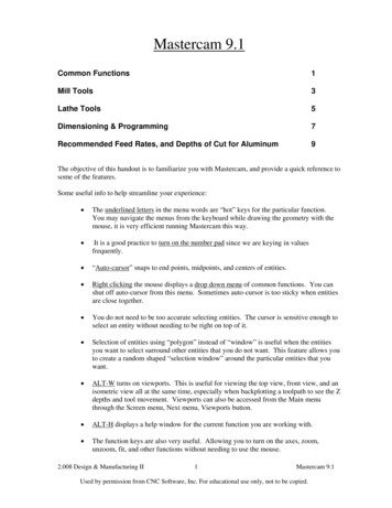
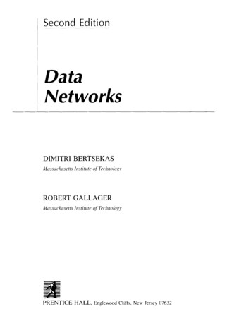
Sec. 2.2The Physical Layer: Channels and Modems41the digital data into s(t) so as to minimize the deleterious effects of this distortion. Notethat a black box viewpoint of the physical channel is taken here, considering the inputoutput relation rather than the internal details of the analog channel. For example, ifan ordinary voice telephone circuit (usually called a voice-grade circuit) is used as theanalog channel, the physical path of the channel will typically pass through multipleswitches, multiplexers, demultiplexers, modulators, and demodulators. For dial-up lines,this path will change on each subsequent call, although the specification of tolerances onthe input-output characterization remain unchanged.2.2.1 FilteringOne of the most important distorting effects on most analog channels is linear timeinvariant filtering. Filtering occurs not only from filters inserted by the channel designerbut also from the inherent behavior of the propagation medium. One effect of filteringis to "smooth out" the transmitted signal set). Figure 2.3 shows two examples in whichset) is first a single rectangular pulse and then a sequence of rectangular pulses. Thedefining properties of linear time-invariant filters are as follows:1. If input s(t) yields output r(t), then for any T, input set - T) yields output ret - T).2. If set) yields ret), then for any real number Ct, ns(t) yields ctr(t).3. If 81 (t) yields 1'1 (t) and se(t) yields re(t), then Sl (t) se(t) yields rj (t) re(t).The first property above expresses the time invariance: namely, if an input is delayed by T, the corresponding output remains the same except for the delay of T. Thesecond and third properties express the linearity. That is, if an input is scaled by ct,the corresponding output remains the same except for being scaled by ct. Also, the. . Dl.: (t )ooTT2T(a)10101 s(t)oT1o0LDI--- -2T3T4T5T6T-,U Il.- I(b)Figure 2.3 Relation of input and output waveforms for a communication channel withfiltering. Part (a) shows the response r(t) to an input 8(t) consisting of a rectangularpulse, and part (b) shows the response to a sequence of pulses. Part (b) also illustrates theNRZ code in which a sequence of binary inputs (I 1 0 I 00) is mapped into rectangularpulses. The duration of each pulse is equal to the time between binary inputs.
42Point-ta-Point Protocols and LinksChap. 2output due to the sum of two inputs is simply the sum of the corresponding outputs.As an example of these properties, the output for Fig. 2.3(b) can be calculated fromthe output in Fig. 2.3(a). In particular, the response to a negative-amplitude rectangularpulse is the negative of that from a positive-amplitude pulse (property 2), the outputfrom a delayed pulse is delayed from the original output (property 1), and the outputfrom the sum of the pulses is the sum of the outputs for the original pulses (property 3).Figure 2.3 also illustrates a simple way to map incoming bits into an analogwaveform s(t). The virtual channel accepts a new bit from the DLe module eachT seconds; the bit value I is mapped into a rectangular pulse of amplitude I, andthe value 0 into amplitude -1. Thus, Fig. 2.3(b) represents s(t) for the data sequence 110100. This mapping scheme is often referred to as a nonreturn to zero (NRZ)code. The notation NRZ arises because of an alternative scheme in which the pulsesin s(t) have a shorter duration than the bit time T, resulting in s(t) returning to 0level for some interval between each pulse. The merits of these schemes will becomeclearer later.Next, consider changing the rate at which bits enter the virtual channel.
data link control (DLC) module supplies bits to the sending side of the modem at a synchronous rate (i.e., one bit each T seconds for some fixed T). If the DLC module temporarily has no data to send, it must continue to send dummy bits, called idle fill, until it again has data. The receiving modem recovers these bits synchronously (with delay and occasional errors) and releases the bits .