Transcription
Understanding ImpedancesHSSP Audio and Speaker-buildingTeacher: Michael PriceWhy do we need to know this?We’re going to build speakers using two or more different drivers (for example, a woofer and a tweeter) to eachcover a specific part of the audible range. For example, we might want to use a 7” cone woofer to play all sounds upto a frequency around 2 KHz, and a 1” dome tweeter to play the higher frequencies - so that together, they make goodmusic. But speaker drivers don’t naturally work that way; we need to add some kind of electrical circuit to each driver,to equalize its frequency-response just the way we want.The power delivered into the a speaker driver (which is proportional to the amount of sound we get out) is thevoltage across the terminals of the speaker times the current going through it. While the actual relationship betweenthose is somewhat complicated, we can predict it very accurately by using Ohm’s law (V IR, or voltage equalscurrent times resistance) and saying that the speaker has a resistance that changes with frequency. That frequencydependent resistance is called impedance; it’s measured in ohms like resistance, but it’s represented by the letter Z.This is the real Ohm’s law:V IZThe trick is in figuring out how to design circuits to filter audio signals based on this principle. This is the basisfor crossover design!Mathematical backgroundImpedance is a property of any two-port passive network (that is, any circuit made from resistors, capacitors, andinductors). Such a network can be condensed into one component that might look like this in schematic form:I VThe voltage V is the potential difference (measured in Volts Joules per Coulomb, or energy per unit charge)across the component. The current I (measured in Amps Coulombs per second) is what flows through the com ponent. The sign convention is that normally a positive current flows into the positive terminal. If you measure thevoltage difference from the bottom to the top instead of top to bottom, your measurement of the current is flippedaround too.One important thing about impedance is that it’s a function of frequency (i.e. Z(ω)). That’s because the scalarequation V IZ is actually only true for a sinusoidal wave (any one frequency). But if you decompose any voltageor current signals into their frequency spectra, V (ω) I(ω)Z(ω) exactly. Engineers are lazy, so they assume youknow that and just write V IZ.The angular frequency ω is measured in radians per second. Since it takes 2π radians to go around a circle, theabsolute frequency (in Hz, or cycles per second) is f 2ωπ . You will see f and 2πω used interchangeably.Another important (and confusing) thing about impedance is that it needs to be described as a complex numberwith both real and imaginary (i 1) parts. To simplify things, instead we state impedance as a magnitude Z (the overall amount of impedance) and phase angle Z. Remember how the woofers in the open baffle made almost
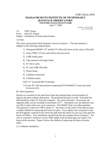
Understanding ImpedancesHSSP Audio and Speaker-buildingSpring 2007no sound when you listened from the side? That’s because the sound coming from the front and back of the speakerhad the same strength (magnitude), but were actually opposing one another. Their phase angles were different by 180degrees, so they cancelled each other out. Electric circuits affect the phase of audio signals just like speakers do; theycan actually shift or delay the sound wave, because inductors and capacitors store and release energy over time. Themain reason we think of it this way is because we don’t want the tweeter and woofer to cancel each other out in thatfrequency range near the crossover point where they are both playing together. We’re going to control the impedancesin our crossover circuits so that the phase of the sound waves coming from the different drivers is aligned.Passive componentsResistors, capacitors and inductors are 2-port passive components. Each of them has an impedance associatedwith it, and using simple rules for series and parallel components, you can compute the impedance of almost anycombination of these components. Resistors: The impedance of a resistor is ZR R, or simply its resistance. There is no imaginary part; themagnitude of the impedance is R and the phase angle is zero at all frequencies. That makes sense, right? Addinga resistor to a system can’t delay or shift a wave form, only decrease its magnitude.Resistances are measured in ohms (Ω), and can be made arbitrarily small or large; values between 1Ω and 50Ωare common in speakers.11 Capacitors: The impedance of a capacitor is ZC iωC i2πfC . The important thing to notice is that thefrequency f times the capacitance C is in the denominator. For any given capacitance, the impedance decreaseswith increasing frequency. And the magnitude of the impedance goes the opposite way from the capacitance:larger capacitors have lower impedance. The i in there means that the impedance is imaginary. It has a phaseangle of -90 degrees. What that means as far as we’re concerned is that the current through a capacitor is actuallyshifted by 14 of a cycle relative to the voltage. If you put in a pure tone where the voltage is alternating backand forth, the current will be highest when the voltage is zero! Don’t you think it would be pretty tough for anamplifier to drive a capacitor?Capacitances are measured in farads (F), although feasible values of capacitors vary from around 1 pF (10 12F) to 10 mF (0.01 F). In speakers you’ll find capacitors between 1µF and 100µF. Inductors: The impedance of an inductor (coil) is ZL iωL i2πf L. It’s the opposite of a capacitor: theimpedance is directly proportional to frequency, and larger inductors have higher impedance. Because the i isn’ton the bottom of a fraction, the phase angle is 90 degrees. In other words, the current in an inductor is alsoshifted 14 of a wave compared to the voltage, but in the opposite direction! What do you think would happen ifyou connected both an inductor and a capacitor in series with a speaker? Would they block all the current at thefrequency where the impedance magnitudes matched?Inductances are measured in henries (H), and commonly show up between 1 µH (10 9 H) and 1 H. The inductorsin speakers are typically 0.1 mH to 10 mH.This picture summarizes the three types of passive components:ResistorCapacitor Constituitive Law:R-V IRImpedance:ZR RInductor Constituitive Law:C-I C dVdtImpedance:1ZC iωC2 Constituitive Law:L-V L dIdtImpedance:ZL iωL
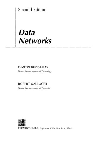
Understanding ImpedancesHSSP Audio and Speaker-buildingSpring 2007Demonstrations and speakersBy hooking up these components in series with a speaker, we saw impedances in action. The capacitor added alot of impedance at low frequencies, so when we connected it in series with a driver, it filtered out the bass - and theeffect was stronger when we used smaller values of capacitance. The inductor added impedance at high frequenciesand made the driver sound softer.Our simple crossover network used an inductor on the woofer and a capacitor on the tweeter. We added a seriesresistor to the tweeter circuit because the tweeter had a higher sensitivity than the woofer we needed to decrease thesignal strength going into the tweeter so the speaker would sound balanced.Here’s a picture to show what’s going on when you connect an inductor in series with a woofer. There are threepictures: On top: This schematic shows that the inductor goes between the positive lead of the amplifier output and thepositive connector on the driver. The little resistor is there because every real inductor has some resistance. In the middle: This is the electrical frequency response. It shows how the addition of the inductor alters thestrength of each frequency component that the driver produces. On the bottom: Acoustic frequency response. This represents the sound coming from the driver. Its originalfrequency response has been multiplied by the electrical frequency response, which declines at higher frequen cies.3
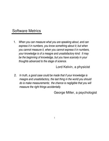
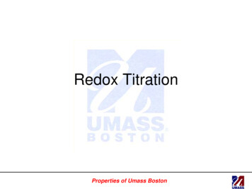
Understanding ImpedancesHSSP Audio and Speaker-buildingSpring 2007We also tried using a ribbon tweeter the funky-looking yellow rectangular one instead of the regular dome. Withthe resistor and capacitor connected like we had before, it sounded a lot better than the other tweeter. Why? Thereisn’t a huge difference in quality between these two drivers.Image of Dayton DC28F Soft dome tweeter due to copyright restrictions.Image of Dayton PT2B Planar magnetictweeter removed due to copyright restrictionsI went on the Internet to look up the impedance curves for those two drivers. Here is what I found:Impedance Comparison of Tweeters13Impedance magnitude ( )12111098765PT2BDC28102103104Frequency (Hz)Image by MIT OCW.The DC28 (a regular soft dome tweeter) had a varying impedance, but the PT2B tweeter’s impedance was nearlyconstant over all frequencies (like a resistor). Even though the crossover network stayed the same, the impedancevariation of the standard tweeter was causing problems in the frequency response! That doesn’t mean that driverswith flat impedance are always better. In fact, we can add components to our circuit (called a “zobel”) that make theimpedance of any driver appear constant to the rest of the network. Then it’s no problem at all.4
Understanding ImpedancesHSSP Audio and Speaker-buildingSpring 2007Series and parallelThese are the rules for finding the impedances of combinations of components: Series connection: If you have two 2-port networks (with impedances Z1 and Z2 ) connected one after the other,the equivalent impedance of that series combination is Zeq Z1 Z2 . The impedance of a bunch of networksconnected in one chain is the sum of all of the individual impedances. Parallel connection: If you have two 2-port networks (with impedances Z1 and Z2 ) connected together, theequivalent impedance of that parallel combination is Zeq ZZ11 ZZ22 .If you put two equal impedances in series, the effective impedance is double what you started with. If you putthem in parallel, you get half of what you started with.Z1Series connectionParallel connectionZ1Zeq Z1 Z2Z2Z2Zeq 1Z11 Z12 Z1 Z2Z1 Z2How about an example? Let’s find the equivalent impedance of this network.CRLThe circuit is a resistor R in series with the parallel combination of the inductor L and capacitor C. First, let’s findthe impedance of the parallel combination of L and C:Z1 ZL iωL1Z2 ZC iωCZ1 Z2ZLC Z1 Z2 ZLCiωLiωC1iωL iωCiωL 1 ω 2 LCNow we can add the resistor’s impedance to that, because they are in series:Zeq ZR ZLCiωL R 1 ω 2 LCR(1 ω 2 LC) iωLZeq 1 ω 2 LC5
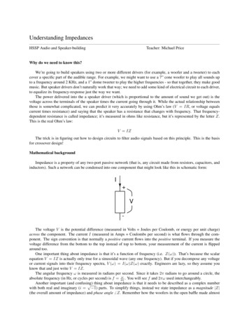
Understanding ImpedancesHSSP Audio and Speaker-buildingSpring 2007That expression is a little complicated. Take a look at the graph of the impedance magnitude versus frequency,Zeq (ω):Impedance of example network5045Impedance magnitude (Ω)4035302520151050210310Frequency (Hz)410Isn’t this interesting? The parallel combination of an inductor and a capacitor is a resonant circuit that has a rela 1tively low impedance at most frequencies, but a very high impedance around the resonant frequency, f0 2πLC(inthis case it’s around 1.6 KHz). The resistor gives this network a minimum impedance (in this case 4 Ω) at frequencieswhere the LC combination acts as a short circuit.If you put this network in series with a speaker, frequencies around 1.6 KHz would get blocked out from the sound,and all of the other frequencies would get a little bit quieter.Higher-order filtersIn the next two weeks we’re going to start using combinations of components in series and parallel, instead ofeverything in series with the driver. It turns out that when you put a component in parallel with a speaker, it tends tohave the opposite effect of when you put it in series. Why?Remember that a capacitor has impedance that decreases with increasing frequency. When you put it in series withthe speaker, the high impedance at low frequencies blocks low-frequency current from flowing through the circuit. Ifyou put it in parallel, connecting the capacitor across the terminals of the speaker and leaving it connected directlyto the amplifier, it has no effect just by itself (besides giving your amplifier a hard time). But what if you add aseries resistance or inductance? That will limit the overall current going into the circuit at high frequencies. Since thecapacitor has low impedance at high frequencies, it “sucks” those currents from the source instead of allowing them topass through the speaker. Just like a series inductor, with the right source impedance a parallel capacitor can be used tofilter out high frequencies. And likewise, putting an inductor in parallel with a speaker will filter out low frequenciesmuch like a series capacitor would.The picture below is a comparison of the effect of a single series inductor, versus that of a series inductor followedby a capacitor in parallel with the speaker. The filter with the capacitor (called an LC filter) is a 2nd-order filter, and itcauses the frequency response to roll off twice as fast (look at the dB scale on the bottom graph).6
Understanding ImpedancesHSSP Audio and Speaker-buildingSpring 2007Let me throw out some numbers for example. The impedance of an inductor, for example, increases proportionalto frequency. Let’s say you have a speaker that’s compensated to have a constant impedance of 6 ohms, and theinductor’s value is L 1 mH (0.001 H). At low frequencies that impedance is small compared to the impedance of thespeaker, so it doesn’t do anything. For example, at 100 Hz the inductor’s impedance magnitude is 2π 100 0.001,which is about 0.6 Ω. not much effect. Then you get to the frequency where the two impedances are equal, and thepower delivered to the speaker is reduced by half (-3 dB). That’s around 1 KHz, because 2π 1000 0.001 is about 6ohms, and the speaker is 6 Ω as well. Then the inductor starts playing a significant part; the frequency response curv
for crossover design! Mathematical background . Impedance is a property of any two-port passive network (that is, any circuit made from resistors, capacitors, and inductors). Such a network can be condensed into one component that might look like this in schematic form: The voltage . V is the potential difference (measured in Volts Joules per Coulomb, or energy per unit charge) across the .