Transcription
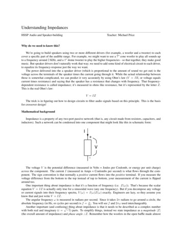
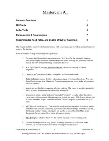
VSRT MEMO #050MASSACHUSETTS INSTITUTE OF TECHNOLOGYHAYSTACK OBSERVATORYWESTFORD, MASSACHUSETTS 01886April 17, 2009Telephone: 781-981-5407Fax: 781-981-0590To:VSRT GroupFrom: Alan E.E. RogersSubject: Installation of Ozone SpectrometerA] PartsThe ozone spectrometer block diagram is shown in Figure 1. The spectrometer isshipped as the following separate parts:1] Wineguard SD4047 18” satellite TV dish with mirror in the center of the dish.2] Fortec FSKU-VN low noise block downconverter3] LNBF holder parts4] Tape measure with angle finder5] 50 RG-6 cable6] 50 sma LMR-100 cable7] Plastic bottle8] Calibrator electronics9] Calibrator probe10] 8” 8” Eccosorb HR-25 absorber11] Linux PC with measurement computing PCI-DAS4020-12 card and ozonedownconverterB] Dish installationDecide on a location for the dish from where the antenna beam can be pointed at 8degrees elevation without obstruction. The preferred direction is south. If possible thedish should be within 50 from the computer. The closer the better. If necessary thesupplied cables can be extended in increments of 25 . Alternately you can fabricate yourown RG-6 cable with screw on F-connectors. The DS4047 dish is an offset parabola.The geometry is shown in VSRT memo 41. The mirror in the center of the dish providesa simple method for measuring the beam elevation. If you adjust your viewpoint so thatthe feed appears centered in the mirror the path from the mirror to your eye is the path thebeam will follow. Your installation should look like the example shown in Figure 2. Besure to wrap the F connector on the LNBF tightly with electrical tape (see Figure 3) tokeep out the moisture. Figure 4 shows the method of measuring the beam elevationangle.C] Calibrator installation1
The frequency calibrator is needed to ensure the spectrometer will center the ozone line(11.0724545 GHz) in the spectrum. The calibrator is not water tight and needs to beprotected from the elements with a plastic bottle. Use silicone sealer to ensure that waterwill not leak down the probe cable into the calibrator. The probe polarization shouldalign with the LNBF. Figure 5 shows details of the calibrator installation.D] Computer and spectrometer installationThe spectrometer downconverter is attached to the outside of the computer. When youset-up the computer the following connection will be needed as illustrated in Figure 6:1] A.C. power to computer2] A.C. power to spectrometer3] RG-6 (F connector) to LNBF4] SMA cable to calibrator5] BNC from the spectrometer card6] Digital I/O from spectrometer to DAS-4020 (this should also be in place)7] Network RJ-45 needed to return data to Haystack8] Keyboard, monitor and mouseApply power and computer should start to boot as the CMOS BIOS was set to power-upupon restoration of power after a power failure. The computer will automatically returnthe ozone data to Haystack once per day. If a keyboard, mouse and monitor are attachedthe user can access the PC. The user name is ozone. If this is a new installation the usershould contact Haystack for pass words and other details. The PC should be able to getdata back to Haystack as long as the internet can be accessed from the networkconnection to the PC.The ozone spectrometer computer contacts Haystack every morning with the previousday’s data. It runs Linux 2.6. For security reasons, all ports will be closed except for 80outgoing (to transmit the data via http). It is highly desirable to allow port 22 incoming(to allow ssh connections in order to patch the system as necessary). If not systempatches will have to be made locally by attaching a keyboard, monitor and mouse. It isnot necessary to provide the computer with a static IP address; DHCP is fine. This setupis intended to be as secure as possible while allowing the unit to transmit data back withminimal intervention (perhaps none at all, short of plugging the cables and turning it on)on your part. This should be discussed with your IT department both to let them knowthat a new computer will be appearing on their network and to identify any securityconcerns that they may have.E] Software running and available test softwareThe ozone spectrometer real time program was loaded and checked at Haystack andshould start running after the pc boots. The commands to load the PCI bus driver for theDAS-4020 and start the program are in /etc/rc.local. If necessary the program can bestopped by the kill command as root. For test purposes the program can be run manuallywith display2
/home/vsrt/ozone/ozspecwhen started by rc.local the –nodisplay option is used. The ozspec program writes to anoutput file about every 70 seconds in the /home/vsrt/ozone/ directory. A new file isstarted each day with a name set by the year and day of year. These files can beprocessed locally using the program /home/vsrt/ozone/ozoneplot.F] Manual calibration of the spectrometerThe system noise temperature is determined by the noise temperature of the LNBF plusthe contribution from the atmosphere and the antenna spillover. The details are in VSRTmemo #45. The LNBF has been measured at Haystack but we provide a piece ofabsorber for a local measurement. The calibration is performed by placing the absorber1over the LNBF, as shown in figure 7, for a few spectrometer cycles (say 5 minutes)removing it for a few cycles and repeating the process for several absorber on/off cycles.The “Y-factor” is the power ratio between the absorber on and the absorber off. The Yfactor should be in the range between 4 and 5 dB. If the Y-factor will also be degraded invery poor weather or when the Sun is in the beam. The spectrometer power for eachspectrum is in the output file and is listed when the file is processed by ozoneplot.G] Photos of the installationPhotos of the installation from the following vantage points are useful:1] From the front2] From the side as a rough check on the pointing elevation – which presumablyyou set using the angle measuring level we sent with the dish.3] In the direction, at the horizon, in which the dish is pointing so we can usegoogle to check the azimuth of the pointing from other features which shouldshow up in the satellite maps.1The denser side should be away from the feed.3
Parts:18" "DirectTV"offset parabolicdishf/dantennaelevation"'\ 0.65beamat 8 deg"' "' "'PC!- DAS4020Liux PCDish nconverterpulsegenMiscTotalMirror for "' "dish alignment"DC passPro be75 ohmterminationownconverter 6iigeneratesLNBF L. 0.10 MHz on/offNotes:1] Feedpointsat g"from bottomof dishand is 13" from this point.2] The frontis 10" fromof thebottom110/220AstrodyneAC -----'PV15-12SLinuxPC 13ve------- 110/220ACfeedof reflector11. 0724545ampGHz ozoneInternetsupplyline 83ohm)HAT-6 cntrlMeasurement4bitsComputingRL207-TP-1 2 -b"-----aPC!- DAS4020PC!ADCVLF-8010 MHz harmonics"calibrate"( BdB 50 ohmvideoGHzLNBF L. 0. 9. 75 GHzFarleeFSKU- VNNF 0.2 0.3 dB120080020203540352222400200200 doun.comFSKU-VN FarleeAstrodyneRadio gikeyspectrometer4 Mar 09Figure 1.4
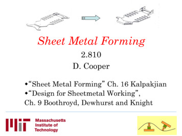
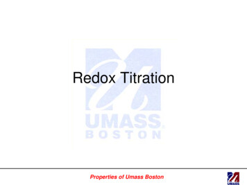
Figure 2. When correctly assembled the LNBF should be 13” ( 0.25”) from a point 9”up from the bottom edge of the reflector. The LNBF should point towards a point 9”from the bottom of the reflector rather than right at the center. The bottom edge of thefront LNBF should be 10” ( 0.25”) from the bottom of the reflector.5
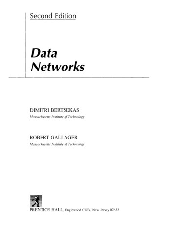
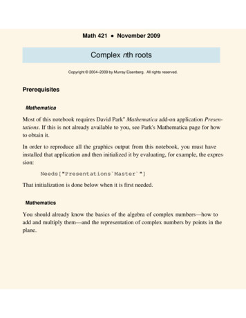
. tr - -- Figure 3. The connector should point down towards the ground and should be well tapedto be sure water doesn’t get into the connector or the attenuator to which it is attached.6
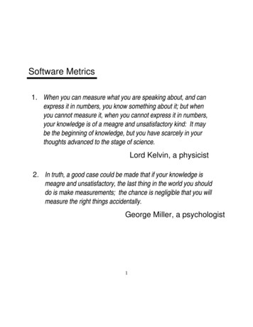
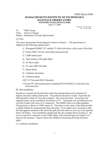
Setting beam elevation of 8 degreesangle 98 degbubble centeredObserve the reflection of the feed in the mirror in the center of the dishFigure 4.7
Figure 5a. When correctly assembled the end of the calibrator probe should be at anangle of 45 degrees.8
10 dB dcpassingattenuator toimprove LNBFmatchTip of thecalibrationprobe isapproximately45 degrees toLNBF outputconnectorBe sure to tapeoverconnections toprevent waterfrom enteringconnectorFigure 5b. Detail of calibrator probe.9
Figure 6.10
Figure 7.11
1] Wineguard SD4047 18” satellite TV dish with mirror in the center of the dish. 2] Fortec FSKU-VN low noise block downconverter 3] LNBF holder parts 4] Tape measure with angle finder 5] 50 RG-6 cable 6] 50 sma LMR-100 cable 7] Plastic bottle 8] Calibrator electronics 9] Calibrator probe 10] 8” 8” Eccosorb HR-25 absorber