Transcription
Mastercam 9.1Common Functions1Mill Tools3Lathe Tools5Dimensioning & Programming7Recommended Feed Rates, and Depths of Cut for Aluminum9The objective of this handout is to familiarize you with Mastercam, and provide a quick reference tosome of the features.Some useful info to help streamline your experience: The underlined letters in the menu words are “hot” keys for the particular function.You may navigate the menus from the keyboard while drawing the geometry with themouse, it is very efficient running Mastercam this way. It is a good practice to turn on the number pad since we are keying in valuesfrequently. “Auto-cursor” snaps to end points, midpoints, and centers of entities. Right clicking the mouse displays a drop down menu of common functions. You canshut off auto-cursor from this menu. Sometimes auto-cursor is too sticky when entitiesare close together. You do not need to be too accurate selecting entities. The cursor is sensitive enough toselect an entity without needing to be right on top of it. Selection of entities using “polygon” instead of “window” is useful when the entitiesyou want to select surround other entities that you do not want. This feature allows youto create a random shaped “selection window” around the particular entities that youwant. ALT-W turns on viewports. This is useful for viewing the top view, front view, and anisometric view all at the same time, especially when backplotting a toolpath to see the Zdepths and tool movement. Viewports can also be accessed from the Main menuthrough the Screen menu, Next menu, Viewports button. ALT-H displays a help window for the current function you are working with. The function keys are also very useful. Allowing you to turn on the axes, zoom,unzoom, fit, and other functions without needing to use the mouse.2.008 Design & Manufacturing II1Mastercam 9.1Used by permission from CNC Software, Inc. For educational use only, not to be copied.
Commonly used function keys:F1: ZOOMF2: UNZOOMF3: REPAINTF9: SHOW X0, Y0 AXESALT F1: FITALT F2: UNZOOM by .8ALT F3: CURSOR TRACKINGF10: KEY ASSIGNMENTS LISTThe button bar across the top has most of these functions.TrimmingAlways select the portion of the entity you want to keep. The portion of the entity on theother side of the intersecting entity will disappear, resulting in trimming the portion you click, to theintersecting entity. Follow the prompts at the lower left of the screen.LevelMain and Visible are most commonly used. Creating your geometry on level 1, and draftingon level 2 works well. You can then make your drafting invisible when you run toolpaths.ColorThis displays the color pallet for changing the colors of entities. The system defaults togreen (#10) for geometry. It also uses certain colors for showing that you have selected an entity, orfor showing a result of a transform. Toolpath feed moves are blue (#11). When you performtransform function, the system identifies the selected entities as a “group” with the color red (#12)and identifies the transformed entities as a “result” with the color purple (#13). Group and resultdesignations are saved with geometry. Rapid movements of toolpaths are yellow (#14). A selectedentity is white (#15).Geometry brought in from Pro Engineer, or Solidworks may be white, change it to green sothe color white can be used as intended. If you want to change the default color it is suggested thatyou use colors other than 10 - 15 to minimize confusion.Branch PointsBranch points are located where the endpoints of three or more entities meet. Branch pointsare not automatically created at intersections. You must break the entities to make them branchpoints. To create a branch point, use the Modify, Trim, or Modify, Break functions.Drafting GlobalsUse this to alter the way dimensioning is displayed. To get to the screen, from the MainMenu go to Create, Drafting, Globals. It will display screens for altering drafting settings. SeeDimensioning, and Editing dimensions on page 7.2.008 Design & Manufacturing II2Mastercam 9.1Used by permission from CNC Software, Inc. For educational use only, not to be copied.
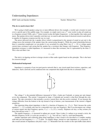
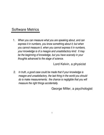
Mill ToolsTools Manager lists all the tools in the tool library, or in your current job. The tools in theTrktools library are the available tools we have setup for the EZ-Trak mills. Clicking on thecolumn headings will sort the list. Generally you will only be accessing this list to get a tool to use.Double clicking on a tool will bring up a graphic display of the tool, showing its length,diameter, and clearance, along with the holder dimensions. Parameter screens allow the editing ofhow the tool is to be used, such as depths of cut and step-over amounts for roughing as well asspeed and feed for the tool to use. These are already setup to fairly good values to minimize toolbreakage. Please refrain from editing the tools; if you believe you may have altered one by mistakeplease let us know so we can refresh it.2.008 Design & Manufacturing II3Mastercam 9.1Used by permission from CNC Software, Inc. For educational use only, not to be copied.
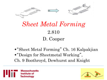
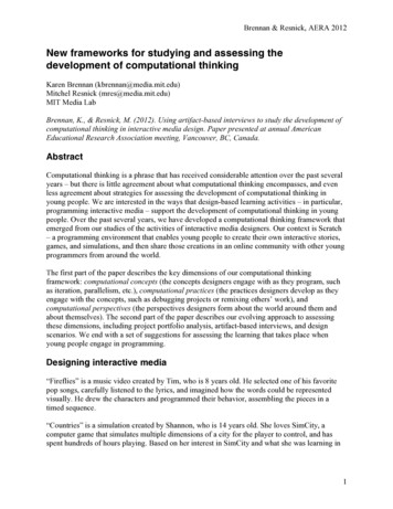
Mill Job SetupIt is important that the toolpath configuration list has the boxes checked as they are in thisscreen shot. It is not necessary to fill out the X, Y, Z fields. Most important is that you do not wantto assign tool numbers sequentially. If they are assigned sequentially the machine will pick up thewrong tools. Open this window when you first start Mastercam Mill. From the Main Menu,Toolpaths, Job Setup.2.008 Design & Manufacturing II4Mastercam 9.1Used by permission from CNC Software, Inc. For educational use only, not to be copied.
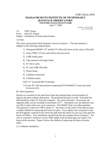
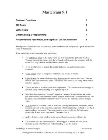
Lathe ToolsLathe Tool Manager lists all the tools in the tool library, or in your current job, dependingon what screens you have opened you will get either one or the other. The tools in the Ltoolslibrary above are the available tools we have in our machine. Hovering the mouse over a tool willdisplay a pop-up graphics view of the tool to aid in choosing the correct tool. Clicking on thecolumn headings will sort the list. Turning off the filter will show all the tools. Generally you willonly be accessing this list to select a tool to use.Highlighting a tool by clicking it once, then clicking OK, will select the tool for theoperation you have chained. Double clicking on a tool opens the parameters of the tool and allowsediting. The right click menu allows you to display the tool by selecting Draw tool, so you can seeif it’s the one you want.Parameter screens for editing tools are not shown in this handout. They allow the editing ofthe tool’s characteristics, such as the geometry of the holder, the insert, the orientation of the tool tothe machine, depths of cut and step-over amounts for roughing as well as speed and feed for the toolto use. These have been tailored by the staff, and are setup to reasonable values to minimize toolbreakage. Please refrain from editing the tools. If you believe you may have altered one by mistakeplease let us know so we can refresh it.Lathe Job Setup2.008 Design & Manufacturing II5Mastercam 9.1Used by permission from CNC Software, Inc. For educational use only, not to be copied.
Stock dimensions must be defined in your geometry for the system to function properlywithout collisions. This will be discussed in the lab. This screen is used to identify where thematerial is, for the system to avoid collisions during entry/exit moves, and positioning moves.Without the use of this screen unpredictable results may occur resulting in possible tool breakage ordamage to the part or the machine. It is important to note that the check box “Assign tool numberssequentially” should not be checked.2.008 Design & Manufacturing II6Mastercam 9.1Used by permission from CNC Software, Inc. For educational use only, not to be copied.
Dimensioning and ProgrammingDimensioningTo alter drafting settings start from the “MAIN MENU”, go to “Create”, “Drafting”, “Globals”. You can alsoedit most elements when you’re in the middle of creating the drafting dimensions. In the process of creatingdrafting a menu of “hot” keys will appear across the top of the geometry screen enabling you to alter the waya dimension looks before you land it in a fixed position.Editing dimensionsGo to “Create”, “Drafting”, “Multi edit”. Select the dimension you want to move or edit, click “Done”. TheDrafting Globals screen will appear. You don’t have to do anything with it just click “OK” to close it. Thenselect the dimension again that you want to alter, (just click it once), now it will move for you and the menuwith the hot keys will be displayed so you can edit the elements before you click again to fix it in a newlocation.Saving filesYou should save your program files with names that are 8 characters or less, and they must have the extension“.txt”. The EZ-Traks are DOS based and will put in a tilde ‘ ’ as the 7th character on long file names.Change the default path to your assigned lab section folder to save your work. Mastercam will default toC:\temp, it is cleaned out when you log off so save your docs to your folder when you begin a session, andsave often.2.008 Design & Manufacturing II7Mastercam 9.1Used by permission from CNC Software, Inc. For educational use only, not to be copied.
Changing the editorFrom the “MAIN MENU”, go to “File”, “Edit”, “Editor”, change to “MCEDIT” if you want to have theoption of changing incremental values to absolute. The default editor will work for normal editing.Incremental (G91) and Absolute (G90)If your geometry is such that it is easier for you to program using incremental values for some features, youmay do so. Enter a “G91” on the lines of code that are incremental values. Be careful to include a “G90” onthe Z-axis moves. You always want to know where the Z-axis is in absolute values. Remember, “G91, and“G90” are in the same modal group and each one will remain in effect until the other is used.If you want to alter a string of incremental values to absolute, so you don’t have to worry about the modeyou’re in (G91, or G90), the “MCEDIT” editor has the function to alter the values.Altering incremental values to absolute values with the “MCEDIT” editor:1. Highlight the lines of code you want to alter. The highlighted lines must include the start point, andthat must be in absolute values, and include both the X, and Y-axes. The start point will not bealtered, but all the values after the start point will be altered, and calculated using the start pointvalues.2. Select the “NC utils” menu in the editor window. Select “Incremental to Absolute”, a dialog boxwill open asking for the axes you wish to alter, select only X, and Y, you want Z to remain absolute.You always want to know where Z is in absolute values.Z-zeroAlways set Z-zero at the top surface of the work-piece. This is the logical place for referencing the Z-axis.The industry standard is such that all Z depths are negative, and any Z positive values are usually in the clearso that you can rapid-position from feature to feature without worrying about running into the work piecewhen you are in the positive region.DrillingDrilling depths are handled totally different than milling depths on the EZ-Trak machines.Drilling depths are taken as incremental positive values from the clearance plane, where as all milling depthsfollow the industry rules and are absolute values and negative when the Z-axis zero is at the top surface of thework-piece.On a “G81”, or “G83” block, you must include the X, and Y values of the hole position even if you havepositioned there from home. The block must also include a positive Z that is the sum of the depth you want todrill plus the clearance plane (R) value, include the R value as well, and the feed rate for the plunge. Forexample: “G81G90X1.Y-.5Z.2R.1F5.” This will drill a hole -.1” deep.For peck drilling (G83), all the above applies but in addition, another Z must be included to state only thepeck amount itself. It is also positive and is an incremental value. The Z for the peck value must follow the Zdepth value. For example: “G83G90X1.Y-.5Z.6Z.09R.1F5.” This will drill to a depth of -.5”, pulling out tothe “R” level every time it drills .09” deeper until reaching the final depth. It is not necessary to make surethat the peck amounts add up to the final depth. The drilling will only go to the final depth.2.008 Design & Manufacturing II8Mastercam 9.1Used by permission from CNC Software, Inc. For educational use only, not to be copied.
Testing handwritten G-codeTesting your program with Reverse Post-processing and using Backplot.1. Save your handwritten program, make sure it is a “.txt” file. Leave it open and displayed so you canedit it easily if there is something wrong.2. Save your Mastercam geometry file, do not change the filename extension leave it as “.MC9”.3. Then in Mastercam from the “MAIN MENU”, click “File”, “New”. Yes, you are sure you want toinitialize Mastercam.4. From the “MAIN MENU”, go to “NC utils”, “Post proc”, “Reverse”, go to where you saved your“.txt” program file and select it. Mastercam will create an “.NCI” (intermediate file) file to write to,it will default to the name you named the “.txt” file, that’s OK. It will display the binary code file itcreates. This binary code file is what it will use to drive the Backplot display.5. Close the “.NCI” file, then go back to the “NC utils” menu and click, “Backplot”. In the lower leftof the screen it will show the “.NCI” filename it will read for the backplot. It should be displayingthe one Mastercam just created, if not, select the NCI file you want to read, by clicking “NCI name”.6. Then click on “Gview: T”, the lowest button on the menu and select “Isometric”, this will enable youto view movement in all 3 axes.7. Then select Step. Each time you click “Step” you will see the movement the program is outputting.Blue lines are feed movements. Yellow lines are rapid moves. If anything looks wrong you can editthe line of code that is causing the problem, and reverse post-process the file again.Recommended Feed Rates for machining Aluminum with HSS end mills.1/16” end mill:1/8” end mill:¼” end mill:3/8” end mill:½” end mill:1.5” end mill:All taper mills:#1Center drill:#4 Center drill:plunge at 2”/min., feed at 4”/minplunge at 3”/min., feed at 5”/minplunge at 5”/min., feed at 10”/minplunge at 5”/min., feed at 15”/minplunge at 5”/min., feed at 15”/minplunge at 5”/min., feed at 20”/minplunge at 5”/min., feed at 10”/minplunge at 5”/min.plunge at 10”/min.Depths of cut for AluminumFor the 1/16”-1/2” end mills: 1/3 the end mill diameter per level.Maximum final depth for the 1/16”-1/2” end mills is 3X their diameters.For the taper mills: 1/16” per level, except the engraving tool.For the 1.5” end mill: .100” per level.Engraving tool: .010” per level to a maximum depth of .030” (the tip angle is 60 degrees).For fine engraving: .005”-.007” max depth. Produce a flat uniform surface by face milling the surface firstusing the 1.5” end mill.2.008 Design & Manufacturing II9Mastercam 9.1Used by permission from CNC Software, Inc. For educational use only, not to be copied.
Mastercam 9.1 Common Functions 1 Mill Tools 3 Lathe Tools 5 Dimensioning & Programming 7 Recommended Feed Rates, and Depths of Cut for Aluminum 9 The objective of this handout is to familiarize you with Mastercam