Transcription
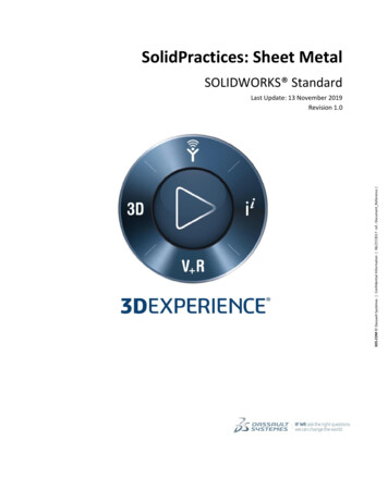
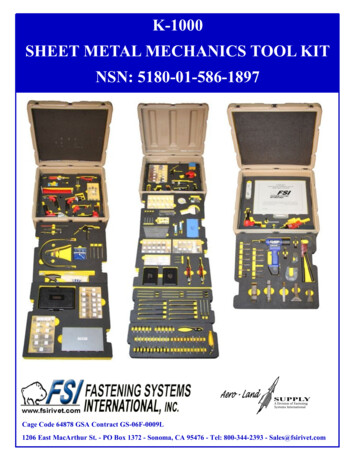
IT, SligoCADME3SHEET METAL IN SOLIDWORKSSheet metal parts are generally used as enclosures for components or to provide support to othercomponents. When you create a sheet metal part in SolidWorks, you generally design the part inthe folded state. This allows you to capture the design intent and the dimensions of the finishedpart.Base FlangeA base flange is the first feature in a new sheet metal part. When you add a base flange featureto a SolidWorks part, the part is marked as a sheet metal part. Bends are added whereverappropriate, and sheet metal specific features are added to the FeatureManager design tree.Note: The Base Flange feature is created from a sketch. The sketch can be a single open, a singleclosed, or multiple-enclosed profiles. There can be only one base flange feature in a SolidWorks part. The thickness and bend radius of the Base Flange feature become the default values for theother sheet metal features.A Base Flange feature creates three new features in the FeatureManager design tree:Sheet-Metal1. The Sheet-Metal feature contains the default bendparameters. To edit the default bend radius, bend allowance, benddeduction, or default relief type, right-click the Sheet-Metalfeature and select Edit Definition.Base-Flange. The Base-Flange feature is the first solid feature ofthis sheet metal part.Flat-Pattern1. The Flat-Pattern feature flattens the sheet metalpart. Notice it is suppressed by default as the part is in its bentstate. Unsuppress the feature to flatten the sheet metal part.When the Flat-Pattern feature is suppressed, all new features thatyou add to the part are automatically inserted above the FlatPattern feature in the FeatureManager design tree. When the FlatPattern feature is unsuppressed, all new features go below it in theFeatureManager design tree and are not shown in the folded part.Edge FlangeThe Edge Flange feature adds a flange to your sheet metal part at an edge that you select.Note: The selected edge must be linear. The thickness is automatically linked to thethickness of the sheet metal part. One sketch line of the profile must lie on theselected edge.Initial Part1Edge Flange Added
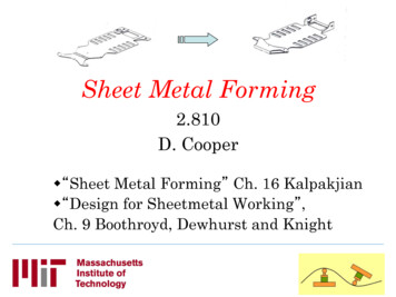
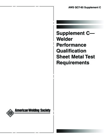
IT, SligoCADME3Miter FlangeA miter flange feature adds a series of flanges to one or more edges of a sheet metal part.Note: The sketch for a miter flange must adhere to thefollowing requirements: The sketch can contain lines or arcs (arccannot be tangent to the thickness edge) The Miter Flange profile can contain morethan one continuous line. For example, it canbe an L-shaped profile. The sketch plane must be normal to the firstedge where the Miter Flange is created. You can create a miter flange feature on a seriesof tangent or non-tangent edgesInitial PartMiter Flange AddedSheet Metal TabA Tab feature adds a tab to the sheet metal part. The depth of a Tab feature is automatically setto the thickness of the sheet metal part. The direction of the depth automatically coincides withthe sheet metal part to prevent a disjoint body.Note: The sketch can be a single closed, multiple closed, or multipleenclosed profile. The illustration shows a single tab feature that addstwo tabs to the sheet metal part. The sketch must be on a plane or planar face that is perpendicular tothe direction of thickness of the sheet metal part. You can edit the sketch, but you cannot edit the definition. This isbecause the depth, direction, and other parameters are set to matchthe parameters of the sheet metal part.Sketched BendYou can add bend lines to the sheet metal part while the part is in its folded state with a sketchedbend feature. This allows you to dimension the bend line to other folded-up geometry.Note: Only lines are allowed in the sketch. You can addmore than one line per sketch. The bend line does not have to be the exact length ofthe faces you are bending.2
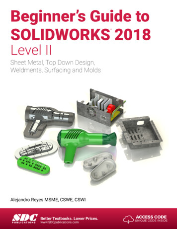
IT, SligoCADME3HemThe Hem tool adds a hem to your sheet metal partat a selected edge.Note: The selected edge must be linear. Mitered corners are automatically added tointersecting hems. If you select multiple edges to add a hem,the edges must lie on the same face.Closed CornerYou can create a Closed Corner feature to extend one face of a Butt rip so it overlaps the otherface of the Butt rip.Note: You can close more than one corner at a time. Select thefaces for all of the rips that you want to close. You can select only planar faces to close. The planar facesmust be perpendicular to each other. A closed corner cannot be applied in some cases whereflange angles are not 90 .Flattening Sheet Metal BendsYou can flatten the bends in a sheet metal part in the following ways: To flatten the entire part, if the Flat-Pattern feature is present, unsuppress Flat-Pattern, or click Flattenedon the Sheet Metal toolbar.The bend lines are shown by default when you unsuppress the Flat-Pattern feature. Tohide the bend lines, expand Flat-Pattern, right-click Bend-Lines, and select HideSketch.To flatten the entire part, if the Process-Bends feature is present, suppress the ProcessBends feature, or click Flattened on the Sheet Metal toolbar.To flatten one or more individual bends, add an Unfoldfeature.Approaches to Sheet Metal Part DesignThere are two ways to create a sheet metal part:1. Build a part, then convert it to sheet metal.2. Create the part as a sheet metal part using sheet metal-specific features. This eliminatesextra steps because you create a part as sheet metal from the initial design stage.There are links in SolidWork on-line help providing information on the following: Design a Part from the Flattened State, then Convert it to Sheet Metal Design a Sheet Metal Part from the Flattened State Design a Part from a Solid, then Convert it to Sheet Metal Design a Sheet Metal Part from a Solid Reasons to Build a Part, then Convert the Part to Sheet Metal Combining the Different Sheet Metal Design Methods3
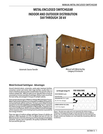
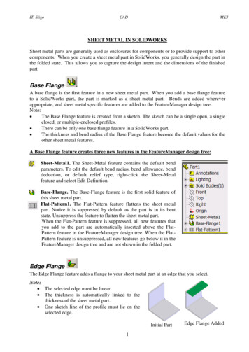
IT, SligoCADME3Sheet Metal ParametersOnce a Sheet-Metal feature is created default bend parameters are applied and used for othersheet metal features. These parameters contain the thickness, default bend radius, bendallowance, bend deduction, or relief type. For any particular bend, specifying custom radius orbend values can change these parameters.Bend AllowanceYou can specify the bend allowance or bend deduction values for your part in a variety of ways.Bend TableK-FactorBend AllowanceBend DeductionAuto ReliefRelief cuts are automatically added wherever needed when inserting bends if you select AutoRelief.The following types of relief cuts are used: Rectangular Tear (minimum size required to insert the bend and flatten the part) ObroundIf you want to automatically add Rectangular or Obround reliefs, you must specify the ReliefRatio.Relief RatioThe distance d represents the width of the Rectangular or Obround reliefcut and the depth by which the side of the Rectangular or Obround reliefcut extends past the bend region. The distance d is determined by thefollowing equation:d (relief ratio) * (part thickness)N.B. The value of the relief ratio must be between 0.05 and 2.0. The higherthe value, the larger the size of the relief cut added during insertion of bends.Examples of (i) Tear, (ii) Obround and (iii) Rectangle4
IT, SligoCADME3Standard SolidWorks ToolsStandard Solidworks tools, such as fillet,chamfer mirror, pattern etc. can be used. Cuttouts canalso be used to create holes and shaped cutouts in a sheet metal part.Unfoldand FoldWith the Unfold and Fold tools, you can flatten and bend one, more than one, or all of the bendsin a sheet metal part.This combination is useful when adding a cut across a bend. First, add an Unfold feature toflatten the bend. Next, add your cut. Lastly, add a Fold feature to return the bend to its foldedstate.RipCreates a rip feature along the selected model edges. A ripfeature is commonly used in sheet metal parts, but you can adda rip feature to any part.JogThe Jog tool adds material to a sheet metal part by creating two bends from a sketched line.Notes: The sketch must contain only one line. The line does not need to be horizontal or vertical. The bend line does not have to be the exact length of the faces you are bending.5
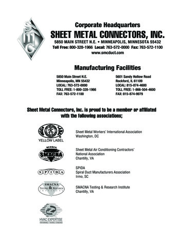
IT, SligoCADME3Sheet Metal Exercise 1 - Sheet Metal TutorialUsing the SolidWorks Tutorials in the Help menu, complete the Sheet Metal assignment.After selecting SolidWorks Tutorials in the Help menu, first choose the option “All SolidWorksTutorials” shown in the Tutorials by Category box on the Home page and then pick the SheetMetal assignment.This involves creating the part shown below and demonstrates the following:Creating a base flange Adding a miter flangeMirroring the part and creating new bendsAdding an edge flange and editing itssketch profileMirroring a featureAdding and bending a tabAdding a cut across a bendFolding and unfolding bendsCreating a closed cornerCreating a sheet metal drawingAdding bend line notesSheet Metal Exercise 2 - BracketCreate a SolidWorks sheet metal model of the Bracket shown below and detailed in the supplieddrawing.On an A3 sheet create a drawing for the sheet metal part. Include a pictorial drawing and anundimensioned Flat pattern (blank development) view of the part.6
Sheet Metal Exercise 2 - Bracket Create a SolidWorks sheet metal model of the Bracket shown below and detailed in the supplied drawing. On an A3 sheet create a drawing for the sheet metal part. Include a pictorial drawing and an undimensioned Flat pattern (blank development) view of the part. Title : Submitting Completed Exercises for Assessment Author: mmoffatt Created Date: 7/9/2014 4:38:53 .