Transcription
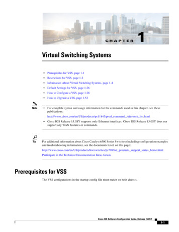
CH A P T E R1Virtual Switching SystemsNote Prerequisites for VSS, page 1-1 Restrictions for VSS, page 1-2 Information About Virtual Switching Systems, page 1-4 Default Settings for VSS, page 1-26 How to Configure a VSS, page 1-26 How to Upgrade a VSS, page 1-52 For complete syntax and usage information for the commands used in this chapter, see cts/ps11845/prod command reference list.html TipCisco IOS Release 15.0SY supports only Ethernet interfaces. Cisco IOS Release 15.0SY does notsupport any WAN features or commands.For additional information about Cisco Catalyst 6500 Series Switches (including configuration examplesand troubleshooting information), see the documents listed on this es/ps708/tsd products support series home.htmlParticipate in the Technical Documentation Ideas forumPrerequisites for VSSThe VSS configurations in the startup-config file must match on both chassis.Cisco IOS Software Configuration Guide, Release 15.0SY1-1
Chapter 1Virtual Switching SystemsRestrictions for VSSRestrictions for VSS General VSS Restrictions, page 1-2 VSL Restrictions, page 1-2 Multichassis EtherChannel (MEC) Restrictions, page 1-2 Dual-Active Detection Restrictions, page 1-3 VSS Mode Service Module Restrictions, page 1-4General VSS Restrictions VSS mode does not support supervisor engine redundancy within a chassis. If you configure a new value for switch priority, the change takes effect only after you save theconfiguration file and perform a restart. Out-of-band MAC address table synchronization among DFC-equipped switching modules (themac address-table synchronize command) is enabled automatically in VSS mode, which is therecommended configuration.VSL Restrictions For line redundancy, we recommend configuring at least two ports per switch for the VSL. Formodule redundancy, the two ports can be on different switching modules in each chassis. The no platform qos channel-consistency command is automatically applied when you configurethe VSL. Do not remove this command. VSL ports cannot be Mini Protocol Analyzer sources (the monitor . capture command). Monitorcapture sessions cannot be started if a source is the VSL on the port channel of the standby switch.The following message is displayed when a remote VSL port channel on the standby switch isspecified and you attempt to start the monitor capture:% remote VSL port is not allowed as capture sourceThe following message is displayed when a scheduled monitor capture start fails because a sourceis a remote VSL port channel:Packet capture session 1 failed to start. A source port is a remote VSL.Multichassis EtherChannel (MEC) Restrictions All links in an MEC must terminate locally on the active or standby chassis of the same virtualdomain. For an MEC using the LACP control protocol, the minlinks command argument defines theminimum number of physical links in each chassis for the MEC to be operational. For an MEC using the LACP control protocol, the maxbundle command argument defines themaximum number of links in the MEC across the whole VSS.Cisco IOS Software Configuration Guide, Release 15.0SY1-2
Chapter 1Virtual Switching SystemsRestrictions for VSS MEC supports LACP 1:1 redundancy. For additional information about LACP 1:1 redundancy, referto the “Information about LACP 1:1 Redundancy” section on page 1-6. An MEC can be connected to another MEC in a different VSS domain. Ports on the supervisor engines are not stateful and will experience a reset across switchovers (seethe “Switchover Process Restrictions” section on page 1-2).Dual-Active Detection Restrictions If Flex Links are configured on the VSS, use PAgP dual-active detection. For dual-active detection link redundancy, configure at least two ports per switch for dual-activedetection. For module redundancy, the two ports can be on different switching modules in eachchassis, and should be on different modules than the VSL, if feasible. When you configure dual-active fast hello mode, all existing configurations are removedautomatically from the interface except for these commands:– description– logging event– load-interval– rcv-queue cos-map– rcv-queue queue-limit– rcv-queue random-detect– rcv-queue threshold– wrr-queue bandwidth– wrr-queue cos-map– wrr-queue queue-limit– wrr-queue random-detect– wrr-queue threshold– priority-queue cos-map Only these configuration commands are available on dual-active detection fast hello ports:– default– description– dual-active– exit– load-interval– logging– no– shutdown ASIC-specific QoS commands are not configurable on dual-active detection fast hello ports directly,but are allowed to remain on the fast hello port if the commands were configured on another non-fasthello port in that same ASIC group. For a list of these commands, see Chapter 1, “Restrictions forPFC QoS.”Cisco IOS Software Configuration Guide, Release 15.0SY1-3
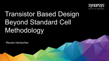
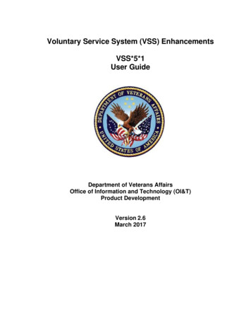
Chapter 1Virtual Switching SystemsInformation About Virtual Switching SystemsVSS Mode Service Module RestrictionsNote When configuring and attaching VLAN groups to a service module interface, use the switch {1 2}command keyword. For example, the firewall vlan-group command becomes the firewall switchnum slot slot vlan-group command. When upgrading the software image of a service module, use the switch {1 2} command keyword. EtherChannel load balancing (ECLB) is not supported between an IDSM-2 in the active chassis andan IDSM-2 in the standby chassis. A switchover between two service modules in separate chassis of a VSS is considered anintrachassis switchover.For detailed instructions, restrictions, and guidelines for a service module in VSS mode, see theconfiguration guide and command reference for the service module.Information About Virtual Switching Systems VSS Overview, page 1-4 VSS Redundancy, page 1-11 Multichassis EtherChannels, page 1-14 Packet Handling, page 1-16 System Monitoring, page 1-20 Dual-Active Detection, page 1-22 VSS Initialization, page 1-24 VSS Topology, page 1-4 Key Concepts, page 1-5 VSS Functionality, page 1-7 Hardware Requirements, page 1-9 Information about VSL Topology, page 1-11VSS OverviewVSS TopologyNetwork operators increase network reliability by configuring switches in redundant pairs and byprovisioning links to both switches in the redundant pair. Figure 1-1 shows a typical networkconfiguration. Redundant network elements and redundant links can add complexity to network designand operation. Virtual switching simplifies the network by reducing the number of network elements andhiding the complexity of managing redundant switches and links.VSS mode combines a pair of switches into a single network element. VSS mode manages the redundantlinks, which externally act as a single port channel.Cisco IOS Software Configuration Guide, Release 15.0SY1-4
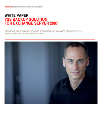
Chapter 1Virtual Switching SystemsInformation About Virtual Switching SystemsVSS mode simplifies network configuration and operation by reducing the number of Layer 3 routingneighbors and by providing a loop-free Layer 2 topology.Figure 1-1Typical Network DesignAccessDistribution181320CoreKey Concepts Virtual Switching System, page 1-5 Active and Standby Chassis, page 1-6 Virtual Switch Link, page 1-6 Multichassis EtherChannel (MEC), page 1-7Virtual Switching SystemA VSS combines a pair of switches into a single network element. For example, a VSS in the distributionlayer of the network interacts with the access and core networks as if it were a single switch. SeeFigure 1-2.An access switch connects to both chassis of the VSS using one logical port channel. VSS mode managesredundancy and load balancing on the port channel. This capability enables a loop-free Layer 2 networktopology. VSS mode also simplifies the Layer 3 network topology because VSS mode reduces thenumber of routing peers in the network.VSS in the Distribution NetworkPhysical viewLogical viewVirtual Distribution SwitchAccessVirtual Distribution SwitchAccess181321Figure 1-2Cisco IOS Software Configuration Guide, Release 15.0SY1-5
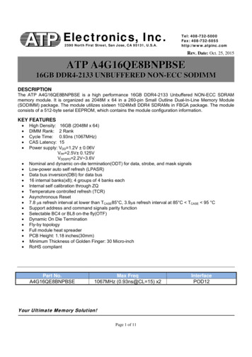
Chapter 1Virtual Switching SystemsInformation About Virtual Switching SystemsActive and Standby ChassisWhen you create or restart a VSS, the peer chassis negotiate their roles. One chassis becomes the activechassis, and the other chassis becomes the standby.The active chassis controls the VSS. It runs the Layer 2 and Layer 3 control protocols for the switchingmodules on both chassis. The active chassis also provides management functions for the VSS, such asmodule online insertion and removal (OIR) and the console interface.The active and standby chassis perform packet forwarding for ingress data traffic on their locally hostedinterfaces. However, the standby chassis sends all control traffic to the active chassis for processing.You can defer the traffic load on a multichassis EtherChannel (MEC) chassis to address traffic recoveryperformance during the standby chassis startup. For example, Figure 1-3 represents network layoutwhere a VSS (active and standby switches) is interacting with an upstream switch (switch 2) and adownstream switch (switch 1).Figure 1-3Switch Interconnected Through VSSSwitch 2PO2ActiveSwitchStandbySwitchSwitch 1282323PO1Virtual Switch LinkFor the two chassis of the VSS to act as one network element, they need to share control information anddata traffic.The virtual switch link (VSL) is a special link that carries control and data traffic between the two chassisof a VSS, as shown in Figure 1-4. The VSL is implemented as an EtherChannel with up to eight links.The VSL gives control traffic higher priority than data traffic so that control messages are neverdiscarded. Data traffic is load balanced among the VSL links by the EtherChannel load-balancingalgorithm.Cisco IOS Software Configuration Guide, Release 15.0SY1-6
Chapter 1Virtual Switching SystemsInformation About Virtual Switching SystemsFigure 1-4Virtual Switch LinkVirtual switchChassis 2181322Chassis 1Virtual switch link(VSL)Multichassis EtherChannel (MEC)An EtherChannel, which is configured on a port channel interface, is two or more physical links thatcombine to form one logical link. Layer 2 protocols operate on the EtherChannel as a single logicalentity.A MEC is a port channel with member ports on both chassis of the VSS. A connected non-VSS deviceviews the MEC as a standard EtherChannel. See Figure 1-5.VSS mode supports a maximum of 512 EtherChannels. This limit applies to the combined total ofregular EtherChannels and MECs. Because the VSL requires two EtherChannel numbers (one for eachchassis), there are 510 user-configurable EtherChannels. Service modules that use an internalEtherChannel are included in the total.Figure 1-5VSS with MECVSLChassis 1Chassis 2181323MECNotePorts on the supervisor engines are not stateful and will experience a reset across switchovers (see the“Switchover Process Restrictions” section on page 1-2).VSS Functionality Redundancy and High Availability, page 1-8 Packet Handling, page 1-8 System Management, page 1-8 Interface Naming Convention, page 1-8 Software Features, page 1-9Cisco IOS Software Configuration Guide, Release 15.0SY1-7
Chapter 1Virtual Switching SystemsInformation About Virtual Switching SystemsRedundancy and High AvailabilityIn VSS mode, supervisor engine redundancy operates between the active and standby chassis, usingstateful switchover (SSO) and nonstop forwarding (NSF). The peer chassis exchange configuration andstate information across the VSL and the standby supervisor engine runs in hot standby mode.The standby chassis monitors the active chassis using the VSL. If it detects failure, the standby chassisinitiates a switchover and takes on the active role. When the failed chassis recovers, it takes on thestandby role.NotePorts on the supervisor engines are not stateful and will experience a reset across switchovers (see the“Switchover Process Restrictions” section on page 1-2).If the VSL fails completely, the standby chassis assumes that the active chassis has failed, and initiatesa switchover. After the switchover, if both chassis are active, the dual-active detection feature detectsthis condition and initiates recovery action. For additional information about dual-active detection, seethe “Dual-Active Detection” section on page 1-22.Packet HandlingThe active supervisor engine runs the Layer 2 and Layer 3 protocols and features for the VSS andmanages the DFC modules for both chassis.The VSS uses VSL to communicate protocol and system information between the peer chassis and tocarry data traffic between the chassis when required.Both chassis perform packet forwarding for ingress traffic on their interfaces. If possible, ingress trafficis forwarded to an outgoing interface on the same chassis to minimize data traffic that must traverse theVSL.Because the standby chassis is actively forwarding traffic, the active supervisor engine distributesupdates to the standby supervisor engine PFC and all standby chassis DFCs.System ManagementThe active supervisor engine acts as a single point of control for the VSS. For example, the activesupervisor engine handles OIR of switching modules on both chassis. The active supervisor engine usesVSL to send messages to and from local ports on the standby chassis.The command console on the active supervisor engine is used to control both chassis. In virtual switchmode, the command console on the standby supervisor engine blocks attempts to enter configurationmode.The standby chassis runs a subset of system management tasks. For example, the standby chassis handlesits own power management.Interface Naming ConventionIn VSS mode, interfaces are specified using switch number (in addition to slot and port), because thesame slot numbers are used on both chassis. For example, the interface 1/5/4 command specifies port 4of the switching module in slot 5 of switch 1. The interface 2/5/4 command specifies port 4 on theswitching module in slot 5 of switch 2.Cisco IOS Software Configuration Guide, Release 15.0SY1-8
Chapter 1Virtual Switching SystemsInformation About Virtual Switching SystemsSoftware FeaturesWith some exceptions, VSS mode has feature parity with non-VSS mode. Major exceptions include: VSS mode does not support supervisor engine redundancy within a chassis. Port-based QoS and PACLs can be applied to any physical port, except VSL ports. PACLs can beapplied to no more than 2,046 ports.Hardware Requirements Chassis and Modules, page 1-9 VSL Hardware Requirements, page 1-9 PFC, DFC, and CFC Requirements, page 1-10 Multichassis EtherChannel Requirements, page 1-10 Service Module Support, page 1-10Chassis and ModulesTable 1-1VSS Hardware RequirementsHardwareCount RequirementsChassis2All chassis supported in Cisco IOS Release 15.0SY support VSS mode.NoteSupervisor Engines2The two chassis need not be identical.Either two VS-SUP2T-10G or two VS-SUP2T-10G-XL supervisorengines.The two supervisor engines must match exactly.Switching Modules2 VSS mode support as shown in the Release Notes.VSS mode does not support 61xx switching modules. In VSS mode,unsupported switching modules remain powered off.VSL Hardware RequirementsThe VSL EtherChannel supports only 40-Gigabit and 10-Gigabit Ethernet ports. The ports can be locatedon the supervisor engine (recommended) or on one of the following switching modules: WS-X6904-40G-2T WS-X6908-10GE WS-X6816-10T-2T, WS-X6716-10T WS-X6816-10G-2T, WS-X6716-10GWe recommend that you use both of the 10-Gigabit Ethernet ports on the supervisor engines to createthe VSL between the two chassis.You can add additional physical links to the VSL EtherChannel by using the 40-Gigabit or 10-GigabitEthernet ports on switching modules that support the VSL.Cisco IOS Software Configuration Guide, Release 15.0SY1-9
Chapter 1Virtual Switching SystemsInformation About Virtual Switching SystemsNote When using the ports on a switching module that can operate in oversubscribed mode as VSL links,you must operate the ports in performance mode, not in oversubscription mode. Enter the nohw-module switch x slot y oversubscription port-group num command when configuring theswitching module. If you enter the no hw-module switch switch number slot slot numberoversubscription command to configure non-oversubscription mode (performance mode), thenonly ports 1, 5, 9, and 13 are configurable; the other ports on the module are disabled. Port-groups are independent of each other and one or more port-groups can operate innon-oversubscribed mode for VSL with the unused ports administratively shutdown, while theothers can still operate in oversubscribed mode.PFC, DFC, and CFC RequirementsSwitching modules with a CFC, DFC4, or DFC4XL support VSS mode.With a PFC4, the VSS will automatically operate in PFC4 mode, even if some of the modules have aDFC4XL. With a PFC4XL, but some modules equipped with a DFC4, you need to configure the VSS tooperate in PFC4 mode. The platform hardware vsl pfc mode non-xl configuration command sets thesystem to operate in PFC4 mode after the next restart. See the “SSO Dependencies” section on page 1-25for further details about this command.Multichassis EtherChannel RequirementsPhysical links from any module with a CFC, DFC4, or DFC4XL can be used to implement aMultichassis EtherChannel (MEC).Service Module Support Application Control Engine (ACE):– ACE20-MOD-K9– ACE30-MOD-K9 ASA Services Module: WS-SVC-ASA-SM1-K9 Firewall Services Module (FWSM): WS-SVC-FWM-1-K9 Network Analysis Module (NAM):– WS-SVC-NAM-1– WS-SVC-NAM-2– WS-SVC-NAM3-6G-K9 Wireless Services Module (WiSM):– WS-SVC-WISM-1-K9– WS-SVC-WISM2NoteBefore deploying a service module in VSS mode, upgrade the module to the minimum supported releasein standalone mode. See the service module release notes for information about the minimum requiredservice module software version.Cisco IOS Software Configuration Guide, Release 15.0SY1-10
Chapter 1Virtual Switching SystemsInformation About Virtual Switching SystemsInformation about VSL TopologyA VSS is two chassis that communicate using the VSL, which is a special port group. Configure both ofthe 10-Gigabit Ethernet ports on the supervisor engines as VSL ports. Optionally, you can also configurethe VSL port group to contain switching module 40- or 10-Gigabit Ethernet ports. This configurationprovides additional VSL capacity. See Figure 1-6 for an example topology.Figure 1-6VSL Topology ExampleVSS Redundancy Overview, page 1-11 RPR and SSO Redundancy, page 1-12 Failed Chassis Recovery, page 1-13 VSL Failure, page 1-13 User Actions, page 1-14OverviewA VSS operates stateful switchover (SSO) between the active and standby supervisor engines. Comparedto standalone mode, VSS mode has the following important differences in its redundancy model: The active and standby supervisor engines are hosted in separate chassis and use the VSL toexchange information. The active supervisor engine controls both chassis of the VSS. The active supervisor engine runs theLayer 2 and Layer 3 control protocols and manages the switching modules on both chassis. The active and standby chassis both perform data traffic forwarding.If the active supervisor engine fails, the standby supervisor engine initiates a switchover and assumesthe active role.Cisco IOS Software Configuration Guide, Release 15.0SY1-11
Chapter 1Virtual Switching SystemsInformation About Virtual Switching SystemsRPR and SSO RedundancyThe VSS normally runs stateful switchover (SSO) between the active and standby supervisor engines(see Figure 1-7). The VSS determines the role of each supervisor engine during initialization.Figure 1-7Chassis Roles in VSS ModeThe VSS uses the VSL link to synchronize configuration data from the active to the standby supervisorengine. Also, protocols and features that support high availability synchronize their events and stateinformation to the standby supervisor engine.VSS mode operates with stateful switchover (SSO) redundancy if it meets the following requirements: Both supervisor engines are running the same software version. The VSL-related configuration in the two chassis matches. The PFC mode matches. SSO and nonstop forwarding (NSF) are configured on both chassis.See the “SSO Dependencies” section on page 1-25 for additional details about the requirements for SSOredundancy on a VSS. See Chapter 1, “Nonstop Forwarding (NSF)” for information about configuringSSO and NSF.With SSO redundancy, the supervisor engine in the standby chassis runs in hot standby state and isalways ready to assume control following a fault on the active supervisor engine. Configuration,forwarding, and state information are synchronized from the active supervisor engine to the redundantsupervisor engine at startup and whenever changes to the active supervisor engine configuration occur.If a switchover occurs, traffic disruption is minimized.If a VSS does not meet the requirements for SSO redundancy, the VSS uses route processor redundancy(RPR). In RPR mode, the active supervisor engine does not synchronize configuration changes or stateinformation with the standby. The standby supervisor engine is only partially initialized and theswitching modules on the standby supervisor are not powered up. If a switchover occurs, the standbysupervisor engine completes its initialization and powers up the switching modules. Traffic is disruptedfor approximately 2 minutes.Cisco IOS Software Configuration Guide, Release 15.0SY1-12
Chapter 1Virtual Switching SystemsInformation About Virtual Switching SystemsFailed Chassis RecoveryIf the active chassis or supervisor engine fails, the VSS initiates a stateful switchover (SSO) and theformer standby supervisor engine assumes the active role. The failed chassis performs recovery actionby reloading the supervisor engine.If the standby chassis or supervisor engine fails, no switchover is required. The failed chassis performsrecovery action by reloading the supervisor engine.The VSL links are unavailable while the failed chassis recovers. After the chassis reloads, it becomesthe new standby chassis and the VSS reinitializes the VSL links between the two chassis.The switching modules on the failed chassis are unavailable during recovery, so the VSS operates onlywith the MEC links that terminate on the active chassis. The bandwidth of the VSS is reduced until thefailed chassis has completed its recovery and become operational again. Any devices that are connectedonly to the failed chassis experience an outage.NoteThe VSS may experience a brief data path disruption when the switching modules in the standby chassisbecome operational after the SSO.After the SSO, much of the processing power of the active supervisor engine is consumed in bringing upa large number of ports simultaneously in the standby chassis. As a result, some links might be broughtup before the supervisor engine has configured forwarding for the links, causing traffic to those links tobe lost until the configuration is complete. This condition is especially disruptive if the link is an MEClink. Two methods are available to reduce data disruption following an SSO: You can configure the VSS to activate non-VSL ports in smaller groups over a period of time ratherthan all ports simultaneously. For information about deferring activation of the ports, see the“Configuring Deferred Port Activation During Standby Recovery” section on page 1-43. You can defer the load sharing of the peer switch’s MEC member ports during reestablishment ofthe port connections. See the “Failed Chassis MEC Recovery” section on page 1-16 for details aboutload share deferral.VSL FailureTo ensure fast recovery from VSL failures, fast link notification is enabled in virtual switch mode on allport channel members (including VSL ports) whose hardware supports fast link notification.NoteFast link notification is not compatible with link debounce mechanisms. In virtual switch mode, linkdebounce is disabled on all port channel members.If a single VSL physical link goes down, the VSS adjusts the port group so that the failed link is notselected.If the standby chassis detects complete VSL link failure, it initiates a stateful switchover (SSO). If theactive chassis has failed (causing the VSL links to go down), the scenario is chassis failure, as describedin the previous section.If only the VSL has failed and the active chassis is still operational, this is a dual-active scenario. TheVSS detects that both chassis are operating in active mode and performs recovery action. See the“Dual-Active Detection” section on page 1-22 for additional details about the dual-active scenario.Cisco IOS Software Configuration Guide, Release 15.0SY1-13
Chapter 1Virtual Switching SystemsInformation About Virtual Switching SystemsUser ActionsFrom the active chassis command console, you can initiate a VSS switchover or a reload.If you enter the reload command from the command console, the entire VSS performs a reload.To reload only the standby chassis, use redundancy reload peer command.To force a switchover from the active to the standby supervisor engine, use the redundancyforce-switchover command.To reset the VSS standby supervisor engine or to reset both the VSS active and VSS standby supervisorengines, use the redundancy reload shelf command.Multichassis EtherChannels Overview, page 1-14 MEC Failure Scenarios, page 1-15OverviewA multichassis EtherChannel is an EtherChannel with ports that terminate on both chassis of the VSS(see Figure 1-8). A VSS MEC can connect to any network element that supports EtherChannel (such asa host, server, router, or switch).At the VSS, an MEC is an EtherChannel with additional capability: the VSS balances the load acrossports in each chassis independently. For example, if traffic enters the active chassis, the VSS will selectan MEC link from the active chassis. This MEC capability ensures that data traffic does notunnecessarily traverse the VSL.Each MEC can optionally be configured to support either PAgP or LACP. These protocols run only onthe active chassis. PAgP or LACP control packets destined for an MEC link on the standby chassis aresent across VSL.An MEC can support up to eight active physical links, which can be distributed in any proportionbetween the active and standby chassis.Cisco IOS Software Configuration Guide, Release 15.0SY1-14
Chapter 1Virtual Switching SystemsInformation About Virtual Switching SystemsFigure 1-8MEC TopologyRouter, switchor serverActive chassisMECSupervisorengineStandby chassis181327Virtual switchSupervisorengineMEC Failure ScenariosNote Single MEC Link Failure, page 1-15 All MEC Links to the Active Chassis Fail, page 1-15 All MEC Links to the Standby Chassis Fail, page 1-16 All MEC Links Fail, page 1-16 Standby Chassis Failure, page 1-16 Active Chassis Failure, page 1-16 Failed Chassis MEC Recovery, page 1-16Configure the MEC with at least one link to each chassis. This configuration conserves VSL bandwidth(traffic egress link is on the same chassis as the ingress link), and increases network reliability (if oneVSS supervisor engine fails, the MEC is still operational).Single MEC Link FailureIf a link within the MEC fails (and other links in the MEC are still operational), the MEC redistributesthe load among the operational links, as in a regular port.All MEC Links to the Active Chassis FailIf all links to the active chassis fail, the MEC becomes a regular EtherChannel with operational links tothe standby chassis.Data traffic terminating on the active chassis reaches the MEC by crossing the VSL to the standbychassis. Control protocols continue to run in the active chassis. Protocol messages reach the MEC bycrossing the VSL.Cisco IOS Software Configuration Guide, Release 15.0SY1-15
Chapter 1Virtual Switching SystemsInformation About Virtual Switching SystemsAll MEC Links to the Standby Chassis FailIf all links fail to the standby chassis, the MEC becomes a regular EtherChannel with operational linksto the active chassis.Control protocols continue to run in the active chassis. All control and data traffic from the standbychassis reaches the MEC by crossing the VSL to the active chassis.All MEC Links FailIf all links in an MEC fail, the logical interface for the EtherChannel is set to unavailable. Layer 2 controlprotocols perform the same corrective action as for a link-down event on a regular EtherChannel.On adjacent switches, routing protocols and Spanning Tree Protocol (STP) perform the same correctiveaction as for a regular EtherChannel.Standby Chassis FailureIf the standby chassis fails, the MEC becomes a regular EtherChannel with operational links on theactive chassis. Connected peer switches detect the link failures, and adjust their load-balancingalgorithms to use only the links to the active chassis.Active Chassis FailureActive chassis failure results in a stateful switchover (SSO). See the “VSS Redundancy” section onpage 1-11 for details about SSO on a VSS. After the switchover, the MEC is operational on the new activechassis. Connected peer switches detect the link failures (to the failed chassis), and adjust theirload-balancing algorithms to use only the links to the new active chassis.Failed Chassis MEC RecoveryWhen a failed chassis returns to service as the new standby chassis, protocol messages reestablish theMEC links between the recovered chassis and connected peer switches.Although the recovered chassis’ MEC links are immediately ready to receive unicast traffic from the peerswitch, received multicast traffic may be lost for a period of several seconds to several minutes. Toreduce this loss, you can configure the port load share deferral feature on MEC port channels of the peerswitch. When load share deferral is configured, the peer’s deferred MEC port channels will establishwith an initial load share of 0. During the configured deferral interval, the peer’s deferred port channelsare capable of receiving
Cisco IOS Software Configuration Guide, Release 15.0SY Chapter 1 Virtual Switching Systems Information About Virtual Switching Systems VSS mode simplifies network configuration and operation by reducing the number of Layer 3 routing neighbors and by providing a loop-free Layer 2 topology. Figure 1-1 Typical Network Design Key Concepts