Transcription
Cisco CatalystVirtual Switching SystemBRKCRS-3035Shawn WargoTechnical Marketing Engineer
Agenda Why VSS? VSS Migration and Architecture Hardware and Software Requirements VSS High Availability and Dual Active VSS Redundant Supervisors VSS Software Upgrades Best Practices and SummaryBRKCRS-3035 2016 Cisco and/or its affiliates. All rights reserved. Cisco Public
Why VSS ?
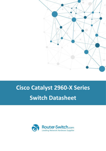
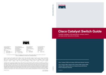
Catalyst Virtual Switching SystemTopology ComparisonsTraditionalVSS - PhysicalVSS - LogicalHSRP orVRRPLACPor PAGPVSLSTP orMSTMECLACP orPAGPAccess SwitchAccess SwitchStackAccess SwitchAccess SwitchStackAccess SwitchAccess SwitchStackBenefits of Virtual SwitchingSimplify Operations by Eliminating STP, FHRP and Multiple Touch-PointsDouble Bandwidth & Reduce Latency with Active-Active Multi-chassis EtherChannel (MEC)5Minimizes Convergence with Sub-second Statefuland Graceful Recovery (SSO/NSF)
Catalyst Virtual Switching SystemSimplified Campus ArchitectureStandalone ChallengesSpanning Tree LoopsFirst Hop Routing ProtocolsFHRP TuningsPIM DR PriorityPIM TuningsProtocol Dependent ScaleUnicast FloodingAsymmetric ForwardingNetwork/System Redundancy TradeoffProtocol Dependent RecoveryCAM/ARP TuningsOSPF LSA/SPF TuningControl/Mgmt/Forwarding ComplexitiesMore VSS BenefitsNetwork/System RedundancyVSSScale-independent RecoveryHardware Dependent RecoveryTraditionalIncrease Unicast CapacityIncrease Multicast CapacityReduced Convergence TimesControl-plane SimplicityOperational SimplicityL2-L4 Load SharingFlat L2 Network Topology
Catalyst Virtual Switching SystemSimplified Campus Architecture Simple and Scalable Network Design Deterministic Network Performance Centralized and Redundant System ArchitectureSingle Unified Management Per LayerMulti-Terabit Distributed Switching CapacityInter-Chassis System and Network-level RedundancyProtocol and Scale Independent ResiliencySupported Catalyst Platforms: C6807-XL – Sup2T or Sup6TC6880-X or C6840-XC6500-E – Sup2T or Sup720C4500-E – Sup7E or Sup8EC4500-X
VSS Simplifies Your ConfigurationStandalone Switch 1Standalone Switch 2VSS (single configuration)! Enable 802.1d per VLAN spanning tree enhancements.spanning-tree mode rapid-pvstspanning-tree extend system-idspanning-tree loopguard defaultspanning-tree uplinkfastspanning-tree backbonefast! Enable STP root for VLAN load-splitting.spanning-tree vlan 2,4,6,8,10,200-400 priority 32768spanning-tree vlan 1,3,5,7,9,100-300 priority 24576! Enable 802.1d per VLAN spanning tree enhancementsspanning-tree mode rapid-pvstspanning-tree extend system-id! Define the Layer 3 SVI for each voice and data VLANinterface Vlan4ip address 10.120.4.3 255.255.255.0no ip redirectsno ip unreachablesload-interval 30! Enable PIM and Reduce query interval to 250 msecip pim sparse-modeip pim query-interval 250 msec! Define HSRP default gateway with 250/800 msec hello/holdstandby 1 ip 10.120.4.1standby 1 timers msec 250 msec 800! Set preempt delay large enough to allow network to stabilize! before HSRP switches back on power on or link recoverystandby 1 preempt delay minimum 180! Enable HSRP authenticationstandby 1 authentication cisco123! Define the Layer 3 SVI for each voice and data VLANinterface Vlan4ip address 10.120.4.1 255.255.255.0no ip redirectsno ip unreachablesip pim sparse-modeload-interval 30L2 Spanning Tree Configuration! Enable 802.1d per VLAN spanning tree enhancements.spanning-tree mode rapid-pvstspanning-tree extend system-idspanning-tree loopguard defaultspanning-tree uplinkfastspanning-tree backbonefast! Enable STP root for VLAN load-splitting.spanning-tree vlan 2,4,6,8,10,200-400 priority 24576spanning-tree vlan 1,3,5,7,9,100-300 priority 32768L3 VLAN IP Configuration! Define the Layer 3 SVI for each voice and data VLANinterface Vlan4ip address 10.120.4.2 255.255.255.0no ip redirectsno ip unreachablesload-interval 30! Enable PIM and Reduce query interval to 250 msecip pim sparse-modeip pim query-interval 250 msec! Define HSRP default gateway with 250/800 msec hello/holdstandby 1 ip 10.120.4.1standby 1 timers msec 250 msec 800! Set preempt delay large enough to allow network to stabilize! before HSRP switches back on power on or link recoverystandby 1 preempt delay minimum 180! Enable HSRP authenticationstandby 1 authentication cisco123
VSS Migration
Migrate from Standalone to VSSRequired One-time Conversion ProcessStart with TwoStandaloneChassisApply One-timeVSS Conversionand ReloadBoth Chassisare now aSingle VSS
Migrate to VSSConversion ExampleFor the purposes of explanation – let’s assume the following setup Switch 2Switch 1Virtual Switch LinkT5/4T5/4T5/5T5/5Port-Channel 1Port-Channel 2Virtual Domain 100
Migrate to VSSConversion Example - TraditionalCONFIGURE THE VSS DOMAIN, SWITCH ID & VSL PORT-CHANNELSwitch 1Router(config)#hostname VSSVSS(config)#switch virtualdomain 1001Domain ID 10 config will take effect onlyafter the exec command 'switch convert mode virtual' domain)#exit1VSS(config)#interface port-channel 1VSS(config-if)#switch virtual linkVSS(config-if)#no shutdownVSS(config-if)#interface range TenGig 5/4 - 5VSS(config-if-range)#channel-group 1 mode onVSS(config-if-range)#no shutdownRouter(config)#hostname VSSVSS(config)#switch virtualdomain 100Domain ID 10 config will take effect onlyafter the exec command 'switch convert mode virtual' isissued21Switch #exit23VSS(config)#interface port-channel 2VSS(config-if)#switch virtual linkVSS(config-if)#no shutdown4VSS(config-if)#interface range TenGig 5/4 - 5VSS(config-if-range)#channel-group 2 mode onVSS(config-if-range)#no shutdown2
Migrate to VSSConversion Example - TraditionalCONVERT FROM STAND-ALONETOVIRTUAL SWITCHINGSwitch 1VSS#switch convert mode virtual5This command will convert all interface names to namingconvention "interface-type switch-number/slot/port", savethe running config to startup-config and reload the switch.Do you want to proceed? [yes/no]: yesConverting interface namesBuilding configuration.[OK]Saving converted configuration to bootflash: .Destination filename [startup-config.converted vs-20141031150039]?AT THIS POINT SWITCH 1 WILL REBOOT.Switch 2VSS#switch convert mode virtualThis command will convert all interface names to namingconvention "interface-type switch-number/slot/port", savethe running config to startup-config and reload the switch.Do you want to proceed? [yes/no]: yesConverting interface namesBuilding configuration.[OK]Saving converted configuration to bootflash: .Destination filename [startup-config.converted vs-20141031150039]?AT THIS POINT SWITCH 2 WILL REBOOT.
Migrate to VSSConversion Example - TraditionalBOTH CHASSIS REBOOT AND NEGOTIATE VSS ROLES Switch 1SWITCH CONSOLE OUTPUTSwitch 2SWITCH CONSOLE OUTPUT System detected Virtual Switch configuration.Interface TenGigabitEthernet 1/5/4 is member of PortChannel 1Interface TenGigabitEthernet 1/5/5 is member of PortChannel 1 System detected Virtual Switch configuration.Interface TenGigabitEthernet 2/5/4 is member of PortChannel 2Interface TenGigabitEthernet 2/5/5 is member of PortChannel 2 00:00:26: %PFREDUN-6-ACTIVE: Initializing as ACTIVE processor forthis switch 00:00:26: %PFREDUN-6-ACTIVE: Initializing as ACTIVE processor forswitchInitializing asVirtual Switch ACTIVEInitializing asprocessorVirtual Switch STANDBYthisprocessor 00:01:19: %VSLP-5-RRP ROLE RESOLVED: Role resolved as ACTIVE by VSLP 00:01:02: %VSLP-5-RRP ROLE RESOLVED: Role resolved as STANDBY by VSLP00:01:19: %VSL-5-VSL CNTRL LINK:00:01:02: %VSL-5-VSL CNTRL LINK:New VSL Control Link5/4New VSL Control Link5/4
15.2(1)SY1Introducing Easy VSS Easy VSS conversion:Traditional VSS conversion:1.Assign Virtual Switch Domain1.Easy VSS Feature can be enabled or disabled2.Assign Switch ID2.Single command line to convert to VSS3.Create Port-channel3.User prompted for Domain ID and VSL details4.Configure Port-channel as VSL5.Add ports to the VSL Port-channel6.“switch convert mode virtual”Start with twoStandalonesystemsApply one-timeVSS ConversionCommands andReloadBoth systemsare now aSingle VSS
15.2(1)SY1Easy VSSConversion ExampleCONVERT FROM STAND-ALONETOVIRTUAL SWITCHINGSwitch 1Switch 2To enable (or disable) the feature:To enable (or disable) the feature:Switch1(config)# switch virtual easySwitch1(config)# switch virtual easyTo convert to VSS:To convert to VSS:switch convert mode easy-virtual-switchswitch convert mode easy-virtual-switchdomain [domain id] links [int1,.,int8]domain [domain id] links [int1,.,int8]Switch1# switch convert mode easy-virtual-switch ?Switch2# switch convert mode easy-virtual-switch ?domainSelect Unique VSL Domain number in yourdomainNetwork, Default domain ID is 100linksSelect VSL LinksSelect Unique VSL Domain number in yourNetwork, Default domain ID is 100linksSelect VSL Links
Migrate to VSSConversion Example - CompleteBOTH SWITCHES ARE NOW CONVERTED TO VSS!Switch 1VSS# show switch virtualSwitch mode:Virtual switch domain number :Local switch number:Local switch operational role:Peer switch number:Peer switch operational role :VSS#Virtual Switch1001Virtual Switch Active2Virtual Switch StandbySwitch 2VSS-sdby enableStandby console disabledVSS-sdby VSS Domain 100Switch 1 VSS ActiveSwitch 2 VSS Hot StandbyNOTE: The standby console isnow disabled for normal CLI input
Migrate to VSSControlling Two Systems from a Single CLISwitch 1VSS# show module switch 1Switch Number:1Role:Virtual Switch Active---------------------- ----------------------------Mod Ports Card TypeModel--- ----- -------------------------------------- -----------------220 DCEF2T 4 port 40GE / 16 port 10GEWS-X6904-40G35 Supervisor Engine 2T 10GE w/ CTS (Acti VS-SUP2T-10G45 Supervisor Engine 2T 10GE w/ CTS (CSSO VS-SUP2T-10G540 DCEF2T 8 port 40GE / 32 port 10GEC6800-32P10G-XL610 DCEF2T 2 port 40GE / 8 port 10GEC6800-8P10G-XL748 CEF720 48 port 1000mb SFPWS-X6848-SFPSerial 8443CZ1SAL1834Z7C2SAL1815QBSCMod MAC addressesHwFwSw--- ---------------------------------- ------ ------------ -----------2 4c00.8269.bef0 to 4c00.8269.bf031.012.2(50r)SYL 15.2(1)SY3 44d3.ca7b.c440 to 44d3.ca7b.c4471.112.2(50r)SYS 15.2(1)SY4 c471.fe7c.d7cc to c471.fe7c.d7d31.312.2(50r)SYS 15.2(1)SY5 1005.caea.e382 to 1005.caea.e3a91.015.1(58r)SYL 15.2(1)SY6 1005.caea.d608 to 1005.caea.d6111.015.1(58r)SYL 15.2(1)SY7 b838.61d8.6fb8 to b838.61d8.6fe73.012.2(18r)S1 ----------Distributed Forwarding CardPolicy Feature Card 4CPU DaughterboardPolicy Feature Card 4CPU DaughterboardDistributed Forwarding CardDistributed Forwarding CardDistributed Forwarding CardDistributed Forwarding CardMod---234567Online Diag OkOkOkSerialHwStatus----------- ------- ------SAL1803KVP7 1.0OkSAL1535NU0L 1.0OkSAL1534NA61 1.1OkSAL1635LRJ8 1.2OkSAL1634L4FS 1.4OkSAL18443CZ1 1.0OkSAL184438FF 1.0OkSAL1834Z7C2 1.0OkSAL1815QDDY 2.0OkSwitch 2VSS# show module switch 2Switch Number:2Role: Virtual Switch Standby---------------------- ----------------------------Mod Ports Card TypeModel--- ----- -------------------------------------- -----------------220 DCEF2T 4 port 40GE / 16 port 10GEWS-X6904-40G35 Supervisor Engine 2T 10GE w/ CTS (Hot) VS-SUP2T-10G45 Supervisor Engine 2T 10GE w/ CTS (CSSO VS-SUP2T-10G540 DCEF2T 8 port 40GE / 32 port 10GEC6800-32P10G-XL620 DCEF2T 4 port 40GE / 16 port 10GEC6800-16P10G-XL748 CEF720 48 port 1000mb SFPWS-X6848-SFPSerial 8443CZ8SAL1834ZAKJSAL1811NKKKMod MAC addressesHwFwSw--- ---------------------------------- ------ ------------ -----------2 e02f.6d6a.8374 to e02f.6d6a.83871.012.2(50r)SYL 15.2(1)SY3 2c54.2dc3.e6c5 to 2c54.2dc3.e6cc1.512.2(50r)SYS 15.2(1)SY4 c471.fe7c.d7ef to c471.fe7c.d7f61.312.2(50r)SYS 15.2(1)SY5 1005.caea.e4ea to 1005.caea.e5111.015.1(58r)SYL 15.2(1)SY6 1005.caea.d59a to 1005.caea.d5ad1.015.1(58r)SYL 15.2(1)SY7 b838.61d8.2b58 to b838.61d8.2b873.012.2(18r)S1 ----------Distributed Forwarding CardPolicy Feature Card 4CPU DaughterboardPolicy Feature Card 4CPU DaughterboardDistributed Forwarding CardDistributed Forwarding CardDistributed Forwarding CardDistributed Forwarding CardMod---234567Online Diag OkOkOkSerialHwStatus----------- ------- ------SAL1808MDJW 1.0OkSAL1737CM1E 2.1OkSAL1736CKTZ 2.0OkSAL1635LRKN 1.2OkSAL1634L4Q4 1.4OkSAL18443CZ8 1.0OkSAL184438FT 1.0OkSAL1834ZAKJ 1.0OkSAL1810N58F 2.0Ok
Migration to VSSHow to configure VSS Ports?VSS ports use a 3-part notation: Interface Type Switch Number /Layer 2 Configuration!interface GigabitEthernet1/3/3switchportswitchport mode accessswitchport access vlan 205logging event link-statusload-interval 30end! Module Number / Port Number Layer 3 Configuration!interface TenGigabitEthernet2/1/1ip address 68.7.1.2 255.255.255.0logging event link-statusload-interval 30ipv6 address 2015:68:7:1::2/96ipv6 ospf 1 area 68!NOTE: The default mode is “routed”. Issue “switchport” to enable L3 CLI
VSS Architecture
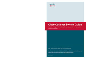
VSS ArchitectureKey ConceptsDefines 2 Catalyst Switches that participate togetheras a Virtual Switching System (VSS)Catalyst Switch that operates as theActive Control Plane for the VSSVirtual Switch 1Active Control PlaneVirtual Switch DomainVirtual Switch LinkActive Data PlaneSpecial 10GE Port-Channel joins two Catalyst Switchesallowing them to operate as a single logical deviceVirtual Switch 2Hot Standby Control PlaneActive Data PlaneCatalyst Switch that operates as theHot Standby Control Plane for the VSS
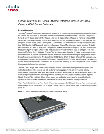
VSS ArchitectureVirtual Switch Link (VSL)The Virtual Switch Link (VSL) joins two physical chassis togetherThe VSL provides a control-plane interface to keep both chassis in syncThe VSS “control-plane” uses the VSL for CPU to CPU communications (programming, statistics, etc.) while the “data-plane” uses the VSLto extend the internal chassis fabric to the remote chassis.A Virtual Switch Link (VSL) Port-Channel can consistof up to 8 x 10GE (or 4 x 40GE) membersVirtual Switch LinkSwitch 1Switch 2VS HeaderL2 HdrL3 HdrDATACRCAll traffic traversing the VSL is encapsulated in a 32 byte “Virtual SwitchHeader” containing Ingress and Egress Port Index, Class of Service (CoS),VLAN ID, other important information from the Layer 2 and Layer 3 header
VSS ArchitectureVSL StartupBefore the VSS Domain can become operational, the VSL mustbe brought online to determine Active and Standby roles.The initialization process essentially consists of 3 steps:1Parse the startup-config to initialize the VSL modules and interfaces2Link Management Protocol (LMP) used to detect Unidirectional Links,Exchange Chassis ID and other information between the 2 switches3LMPLMPRRPRRPRole Resolution Protocol (RRP) used to determine compatible Hardware & Software versionsand determine which switch becomes Active & Hot Standby control-plane
VSS ArchitectureVSL Startup Summary1InitializationInitialization12Rommon & Parse VS ConfigRommon & Parse VS Config23Bring Up VSL Cards & PortsBring Up VSL Cards & Ports34VSLP – Run LMPVSLP – Run LMP45VSLP – Run RRPVSLP – Run RRP56Inter-Chassis SSO SyncInter-Chassis SSO Sync67Continue IOS BootupContinue IOS Bootup7T5/4Switch 1Virtual Switch LinkT5/5Port-Channel 1T5/4T5/5Port-Channel 2Switch 2
VSS ArchitectureSingle Unified Control PlaneOne Supervisor in each Chassis operates inter-chassis Stateful Switch-Over (SSO)One Supervisor is elected ACTIVE with the other in HOT STANDBY mode Active / Standby Supervisors run in SSO Mode – Boot variable, Running-Config, Protocol State, and Line Card Status are fully synchronized Active Supervisor manages all Control-Plane Functions - including Infrastructure Management (Online Insertion Removal, Port Manager,Feature Manager, etc.) and all L2/L3 Protocols (STP, IP Routing, EtherChannel, SNMP, Telnet, etc.)VSLCFC or DFC Line CardCFC or DFC Line CardCFC or DFC Line CardCFC or DFC Line CardCFC or DFC Line CardCFC or DFC Line CardSFRPSFPFCActive SupervisorRPPFCStandby HOT SupervisorSSO SynchronizationCFC or DFC Line CardCFC or DFC Line CardCFC or DFC Line CardCFC or DFC Line CardCFC or DFC Line CardCFC or DFC Line Card
VSS ArchitectureDual Active Data PlanesBoth data forwarding planes are ACTIVEStandby Supervisor and all Line Cards are actively forwarding!VSS# show switch virtual redundancyMy Switch Id 1Peer Switch Id 2 snip DataPlaneActiveDataPlaneActiveSwitch 1 Slot 5 Processor Information rent Software state ACTIVE snip Fabric State ACTIVEControl Plane State ACTIVESwitch 2 Slot 5 Processor Information rent Software state STANDBY HOT (switchover target) snip Fabric State ACTIVEControl Plane State STANDBYSwitch1Switch2
VSS ArchitectureMulti-chassis EtherChannel (MEC)Prior to VSS, an EtherChannel had to be in the same physical switch: Single Module (EC) or Cross Module (DEC)In a VSS, two chassis form a single logical entity, which creates a new DEC:Multi-chassis EtherChannel (MEC)VSSStand AloneLACP, PAGP and ONEtherChannel modesare supportedDistributed EtherChannel (DEC)in a Single ChassisMulti-chassis EtherChannel (MEC)across 2 VSS Chassis
VSS ArchitectureCatalyst 6500/6800 Sup2T / Sup6T MEC Load-Balance SchemesC6K S2T VSS(config)# port-channel load-balance ?dst-ipDst IP Addrdst-macDst Mac Addrdst-mixed-ip-portDst IP Addr and TCP/UDP Portdst-portDst TCP/UDP PortmplsLoad Balancing for MPLS packetssrc-dst-ipSrc XOR Dst IP Addrsrc-dst-macSrc XOR Dst Mac Addrsrc-dst-mixed-ip-portSrc XOR Dst IP Addr and TCP/UDP Portsrc-dst-portSrc XOR Dst TCP/UDP Portsrc-ipSrc IP Addrsrc-macSrc Mac Addrsrc-mixed-ip-portSrc IP Addr and TCP/UDP Portsrc-portSrc TCP/UDP Portvlan-dst-ipVlan, Dst IP Addrvlan-dst-mixed-ip-portVlan, Dst IP Addr and TCP/UDP Portvlan-src-dst-ipVlan, Src XOR Dst IP Addrvlan-src-dst-mixed-ip-portVlan, Src XOR Dst IP Addr and TCP/UDP Portvlan-src-ipVlan, Src IP Addrvlan-src-mixed-ip-portVlan, Src IP Addr and TCP/UDP Port
VSS ArchitectureCatalyst 4500-E Sup7 / Sup8 and Catalyst 4500-X MEC Load-Balance SchemesC4K VSS(config)# port-channel load-balance ?dst-ipDst IP Addrdst-macDst Mac Addrdst-portDst TCP/UDP Portsrc-dst-ipSrc XOR Dst IP Addrsrc-dst-macSrc XOR Dst Mac Addrsrc-dst-portSrc XOR Dst TCP/UDP Portsrc-ipSrc IP Addrsrc-macSrc Mac Addrsrc-portSrc TCP/UDP Port
VSS ArchitectureLoad-Balancing for MEC & ECMPThe PFC / DFC hash logic used for MEC and ECMP load-balancing(to determine the physical port to use) is skewed to always favor LOCAL links!This avoids overloading the Virtual Switch Link (VSL) with unnecessary traffic loads LogicalInterfacePhysicalInterfacePO 10T 1/1/1PO 10T2/1/1Result Bundle Hash(RBH) acePO 10T 1/1/1PO 10T2/1/1Result Bundle Hash(RBH) Value0,1,2,3,4,5,6,7VSSBlue Traffic destined forthe Neighbor will result inLink 1 being chosenOrange Traffic destined forthe Neighbor will result inLink 2 being chosenLink 1Link 2
VSS ArchitectureHow to check an MECVSS# show etherchannel 1 port-channelPort-channels in the group:---------------------Port-channel: Po1-----------Age of the Port-channel 2d:21h:10m:59sLogical slot/port 46/1Number of ports 2GC 0x00000000HotStandBy port nullPassive port list Te1/6/4 Te1/6/5Port state Port-channel L3-Ag Ag-InuseProtocol Fast-switchover disabledLoad share deferral disabledLoad values assigned to each portPorts in the Port-channel:IndexLoadPortEC stateNo of bits------ ------ ------------ ------------------ ----------095Te1/6/4On416ATe1/6/5On4Time since last port bundled:2d:21h:08m:34sLast applied Hash Distribution Algorithm: AdaptiveTe1/6/5Hash distribution method
VSS ArchitectureEtherChannel HashAn IOS command can be used to determine which physical link in the MEC will be usedIt can use various hash inputs to yield an 8-bucket RBH value that will correspond to one of the portsVSSVSS# show etherchannel load-balance hash-result interface port-channel 10 switch 1 ip 10.1.1.1 20.1.1.1Computed RBH: 0x4Would select Gi2/2/1 of Po10When using VSS it is important to add switch # with the hash result command,if not the CLI assumes switch 1 when commuting hash results.
VSS Enabled Campus DesignUnicast ECMP Traffic Flows ECMP forwarding also favors locally attached interfaces FIB first inserts entries for ECMP routes using local links If all local links fail, the FIB is programmed to forward acrossthe VSL (to remote links)T1/2/1T1/2/2VSS6500-vss# show ip route 10.121.0.0 255.255.128.0 longer-prefixesD10.121.0.0/17[90/3328] via 10.122.0.33, 2d10h, TenGigabitEthernet2/2/1[90/3328] via 10.122.0.27, 2d10h, TenGigabitEthernet1/2/1[90/3328] via 10.122.0.22, 2d10h, TenGigabitEthernet2/2/2[90/3328] via 10.122.0.20, 2d10h, TenGigabitEthernet1/2/2Four ECMPEntries6500-vss# show mls cef 10.121.0.0 17 switch 1Codes: decap - Decapsulation, - Push LabelIndex PrefixAdjacency102400 10.121.0.0/17Te1/2/2, 0012.da67.7e40 (Hash: 0001)Te1/2/1, 0018.b966.e988 (Hash: 0002)Two FIB Entries
VSS Hardware andSoftware Requirements
VSS is supported on Catalyst 6500, 6800, 4500-E and 4500-X6500-E / 6807-XL6880-X / GFixed (Based on Sup2T)Sup7E, Sup7LESup8E, Sup8LEFixed (based on Sup7E)Software TrainsSup6T – 15.3(1)SY6880-X - 15.2(1)SY,Sup2T – 15.2(1)SY,15.1(1)SY15.1SY, 15.0SY6840-X – 15.2(2)SYSup720 – es*after release 3.5.0ENomust use the samemodel, 16-port or 32-portN/ANoN/AN/AYes*after release 3.8.0EN/AMixed / Asymmetric YesChassis SupportQuad-Sup SSOSup6T – 15.3(1)SYSup2T – 15.1(1)SY1Quad-Sup RPRSup720 –12.2(33)SXI4(Uplink Forwarding)
VSS RequirementsCatalyst 6500 and 6800 VSS SupportCatalyst 6500 SeriesCatalyst 6800 Series
VSS RequirementsCatalyst 6500 and 6800 VSS Support MatrixHardwareChassisSupervisorModulesCatalyst 0GCatalyst 4-X-LE-40GC6840-X-LE-40GN/AN/ACurrent 6700, 6800 and 6900 series modules are VSL capableLegacy 6100 to 6500 series modules are not supported
VSS RequirementsCatalyst 4500-E and 4500-X VSS SupportCatalyst 4500-E SeriesCatalyst 4500-X Series
VSS RequirementsCatalyst 4500-E and 4500-X VSS Support MatrixHardwareChassisSupervisorModulesCatalyst 4500-E4503 E4506 E4507 E4510R ESup7-ESup7-LESup8-EWS-X4712-SFP EWS-X4748-12X48UWS-X4748-RJ45 VWS-X4748-UPOE EWS-X4748-RJ45-ECatalyst 4500-XWS-C4500X-32SFP WS-C4500X-F-32SFP WS-C4500X16SFP WS-C4500X-F-16SFP /AC4KX-NM-8SFP WS-X4606-X2-EWS-X4648-RJ45V-EWS-X4648-RJ45V 612-SFP-ECurrent 4600 and 4700 series modules are VSL capableLegacy 4500 and 4200 series modules are not supported
VSS High Availability
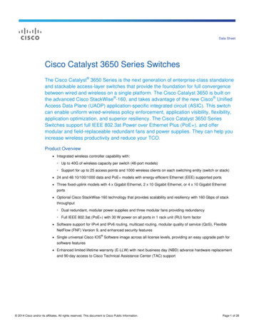
Virtual Switching SystemInter Chassis SSO/NSF2The original Standby Supervisor now takesover as the new Virtual Switch ActiveVirtual Switch initiates Graceful Restart (NSF)Non Stop Forwarding of packets continuesusing hardware entries synched to Switch 2Virtual Switch ActiveSwitch 1Virtual Switch Hot StandbyNSF Aware neighbors exchange protocolupdates with the new Virtual Switch ActiveSwitch 2Switch Is Down1Virtual Switch ActiveVirtual Switch incurs a failure of the(SSO) Active Supervisor in Switch 1The Standby Supervisor detects failureby loss of all VSL ports, or no replies toSSO keep-alive packetsSwitch 1Switch 2
High AvailabilityRedundancy SchemesThe default redundancy mechanism between for VSS is SSOSwitch 1Switch 215.1(2)SY415.1(2)SY4ActiveSSOStandbyIf a mismatch of occurs between the Active & Standby, the Standby will revert to RPR modeSwitch 1Switch 215.1(1)SY115.1(2)SY4ActiveRPRStandby
High AvailabilitySSO & NSF – L2 & L3 Graceful RestartNon-Stop Forwarding (NSF), combined with SSO, minimizes traffic loss during Switchover.NSF Aware neighbors continue to forward traffic, using SSO synchronized hardware entries Switch 1Switch 215.1(2)SY415.1(2)SY4ActiveSSO NSFStandbyVSS# config tVSS(config)# router ospf 1VSS(config-router)# nsf VSS# show ip ospfRouting Process "ospf 10" with ID 192.168.2.1Start time: 00:15:29.344, Time elapsed: 23:12:03.484Supports only single TOS(TOS0) routesExternal flood list length 0Non-Stop Forwarding enabledIETF NSF helper support enabledCisco NSF helper support enabledReference bandwidth unit is 100 mbps NSF is supported byBGP, EIGRP,OSPF & IS-IS
High AvailabilityFailure of MEC member – Upstream TrafficNo Change in Network Topology!Convergence time is determined byNeighbor EtherChannel recalculation Neighbor EtherChannel convergenceis typically 100-200ms Only the flows on the Failed Link(s)are affected (recalculated)231
High AvailabilityFailure of MEC member – Downstream Traffic1No Change in Network Topology!Convergence time is determined byVSS EtherChannel recalculation3 VSS EtherChannel convergence istypically 50-100ms Only the flows on the Failed Link(s)are affected (recalculated)2
Dual-Active Scenarios
High AvailabilityDual-Active DetectionAll neighbors view a “VSS” as asingle Entity, single MAC, single IP!What happens if the VSL is broken?“Dual-Active” is VERY UNLIKEY,because the VSL should always bedeployed as a multi-link Port ChannelVSLHowever IT IS POSSIBLE! Recommend to deploy the VSL with 2 or more links, distributed across multiple Cards to ensure the highest redundancy
High AvailabilityDual-Active DetectionIf the entire VSL bundle fails, the VSS Domain will enterinto a “Dual Active” scenarioBoth switches transition to SSO Active state, and sharethe same network configuration IP address, MAC address, Router ID, etc.This can cause communication problems in the network!3 Step ProcessVSL1Dual-Active Detection - using any detection methodenabled in the system.2Previous VSS Active shuts down ALL interfaces, andenters “Recovery Mode” to prevent further network disruption3Dual-Active Recovery - when the VSL recovers, the switch inRecovery Mode will reload to boot to the VSS Standby state
High AvailabilityDual-Active ProtocolsEnhancedPAGPSwitch 1ActiveSwitch 2Standby Requires ePAGP capableneighbor:VSLP Fast HelloSwitch 1ActiveVSLPVSLPSwitch 2Standby Direct L2 Point-to-Point Connection Requires 12.2(33)SXI 3750: 12.2(46)SE 4500: 12.2(44)SE 6500: 12.2(33)SXH1 Sub-Second Convergence Typically 200-250ms Sub-Second Convergence Typically 50-100msInstant Access (FEX)Switch 1ActiveSwitch 2Standby Requires Dual-Home IA Client Only for C6500 / C6800 Requires 15.1(2)SY2 Sub-Second Convergence Typically 150-200ms
High AvailabilityDual-Active: Recovery Mode%DUAL ACTIVE-SW1 SP-1-DETECTION: Dual-active condition detected:all non-VSL and non-excluded interfaces have been shut downVSS#show switch virtual dual-active summaryPagp dual-active detection enabled: YesBfd dual-active detection enabled: YesActiveRecoveryNo interfaces excluded from shutdown in recovery modeVSLIn dual-active recovery mode: YesTriggered by: Pagp detectionTriggered on interface: Gi1/2/3Dual-ActiveDetected
High AvailabilityDual-Active Detection – Exclude InterfacesUpon detection of a Dual Active scenario, ALL localinterfaces on the Previous-Active are brought down,to avoid disrupting the remainder of the network.The “exclude interface” command excludes the VSL portmembers and any pre-configured local interfaces used formanagement purposes ActiveRecoveryG2/5/1G1/5/1VSS#conf tEnter configuration commands, oneVSS(config)#switch virtual vs-domain)#dual-activeVSS(config-vs-domain)# ZVSS#per line. End with CNTL/Z.100exclude interface Gig 1/5/1exclude interface Gig 2/5/1VSL
High AvailabilityDual Active: Recovery ModeImportant: DO NOT make ANY configurationchanges while in Dual Active Recovery mode!If the running-config has changed,the Recovery Mode switch will NOTautomatically reload! You must issue a“write memory” commandand manually reload the switch in recoverymode, using the “reload shelf” command.ActiveRecoveryVSL
VSS SupervisorRedundancy
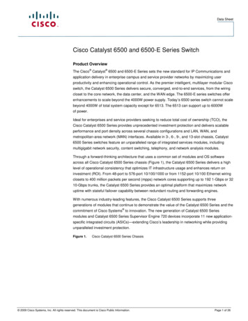
VSS Quad Supervisor SupportWhy Are Redundant Supervisors Needed?1.A Supervisor failure will decreaseavailable VSS bandwidth by 50%2.Some devices may be single-attachto the VSS (for whatever reasons)3. Single NIC Servers, AP’s, Phones, Cameras Service Modules in Local VSS chassis Geographic Separation of VSS chassisRecovery requires manual intervention Failed Supervisor requires onsite hardware removal Replacement Supervisor requires hardware installation Replacement Supervisor requires software installation Replacement Supervisor requires copy of VSS config Non-Deterministic Outage Time!!!
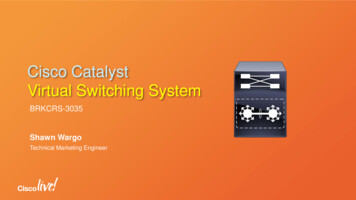
VSS Single SupervisorNormal Operation & SSO RedundancyAvailableBandwidth100%50%TimeControl Plane ActiveData Plane ActiveControl Plane StandbyData Plane Active
VSS Single Sup OperationSupervisor Failure ExampleAvailableBandwidth100%50%TimeControl Plane ActiveData Plane ActiveControlControl PlanePlane StandbyActiveData PlanePlane ActiveActiveData
VSS Single Sup OperationS
VSS(config)#switch virtual domain 100 Domain ID 10 config will take effect only after the exec command 'switch convert mode virtual' is issued VSS(config-vs-domain)#switch 1 VSS(config-vs-domain)#exit VSS(config)#interface port-channel 1 VSS(config-if)#switch virtual link 1 VSS(config-if)#no shutdown VSS(config-if)#interface range TenGig 5/4 - 5