Transcription
C H A P T E R4Configuring Virtual Switching SystemsThis chapter describes how to configure a virtual switching system (VSS) for the Catalyst 6500 seriesswitch. Cisco IOS Release 12.2(33)SXH1 and later releases support VSS.NoteFor complete syntax and usage information for the commands used in this chapter, see thesepublications: The Cisco IOS Virtual Switch Command Reference at this mmand/reference/vs book.html The Cisco IOS Release 12.2 publications at this l/ps1835/products installation and configuration guides list.htmlTipFor additional information about Cisco Catalyst 6500 series switches (including configuration examplesand troubleshooting information), see the documents listed on this es/ps708/tsd products support series home.htmlThis chapter consists of these sections: Understanding Virtual Switching Systems, page 4-1 VSS Configuration Guidelines and Restrictions, page 4-27 Configuring a VSS, page 4-29 Upgrading a VSS, page 4-54Understanding Virtual Switching SystemsThese sections describe a VSS: VSS Overview, page 4-2 VSS Redundancy, page 4-11 Multichassis EtherChannels, page 4-14Cisco IOS Software Configuration Guide, Release 12.2SXOL-13013-064-1
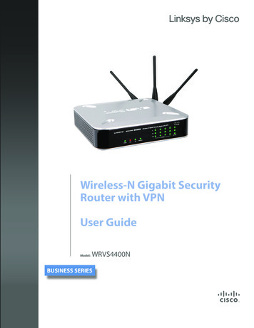
Chapter 4Configuring Virtual Switching SystemsUnderstanding Virtual Switching Systems Packet Handling, page 4-16 System Monitoring, page 4-20 Dual-Active Detection, page 4-22 VSS Initialization, page 4-24 VSS Configuration Guidelines and Restrictions, page 4-27VSS OverviewNetwork operators increase network reliability by configuring redundant pairs of network devices andlinks. Figure 4-1 shows a typical switch network configuration. Redundant network elements andredundant links can add complexity to network design and operation. Virtual switching simplifies thenetwork by reducing the number of network elements and hiding the complexity of managing redundantswitches and links.A VSS combines a pair of Catalyst 6500 series switches into a single network element. The VSSmanages the redundant links, which externally act as a single port channel.The VSS simplifies network configuration and operation by reducing the number of Layer 3 routingneighbors and by providing a loop-free Layer 2 topology.Figure 4-1Typical Switch Network DesignAccessDistribution181320CoreThe following sections present an overview of the VSS. These topics are covered in detail in subsequentchapters: Key Concepts, page 4-3 VSS Functionality, page 4-6 Hardware Requirements, page 4-8 Understanding VSL Topology, page 4-11Cisco IOS Software Configuration Guide, Release 12.2SX4-2OL-13013-06
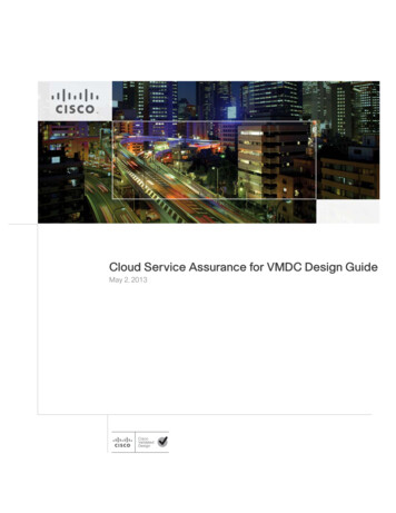
Chapter 4Configuring Virtual Switching SystemsUnderstanding Virtual Switching SystemsKey ConceptsThe VSS incorporates the following key concepts: Virtual Switching System, page 4-3 VSS Active and VSS Standby Chassis, page 4-3 Virtual Switch Link, page 4-4 Multichassis EtherChannel, page 4-5Virtual Switching SystemA VSS combines a pair of switches into a single network element. For example, a VSS in the distributionlayer of the network interacts with the access and core networks as if it were a single switch. SeeFigure 4-2.An access switch connects to both chassis of the VSS using one logical port channel. The VSS managesredundancy and load balancing on the port channel. This capability enables a loop-free Layer 2 networktopology. The VSS also simplifies the Layer 3 network topology because the VSS reduces the numberof routing peers in the network.VSS in the Distribution NetworkPhysical viewLogical viewVirtual Distribution SwitchAccessVirtual Distribution SwitchAccess181321Figure 4-2VSS Active and VSS Standby ChassisWhen you create or restart a VSS, the peer chassis negotiate their roles. One chassis becomes the VSSactive chassis, and the other chassis becomes the VSS standby.The VSS active chassis controls the VSS. It runs the Layer 2 and Layer 3 control protocols for theswitching modules on both chassis. The VSS active chassis also provides management functions for theVSS, such as module online insertion and removal (OIR) and the console interface.The VSS active and VSS standby chassis perform packet forwarding for ingress data traffic on theirlocally hosted interfaces. However, the VSS standby chassis sends all control traffic to the VSS activechassis for processing.Cisco IOS Software Configuration Guide, Release 12.2SXOL-13013-064-3
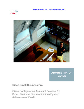
Chapter 4Configuring Virtual Switching SystemsUnderstanding Virtual Switching SystemsVirtual Switch LinkFor the two chassis of the VSS to act as one network element, they need to share control information anddata traffic.The virtual switch link (VSL) is a special link that carries control and data traffic between the twochassis of a VSS, as shown in Figure 4-3. The VSL is implemented as an EtherChannel with up to eightlinks. The VSL gives control traffic higher priority than data traffic so that control messages are neverdiscarded. Data traffic is load balanced among the VSL links by the EtherChannel load-balancingalgorithm.Figure 4-3Virtual Switch LinkVirtual switchChassis 2Virtual switch link(VSL)181322Chassis 1When you configure VSL all existing configurations are removed from the interface except for specificallowed commands. When you configure VSL, the system puts the interface into a restricted mode.When an interface is in restricted mode, only specific configuration commands can be configured on theinterface.The following VSL configuration commands are not removed from the interface when it becomesrestricted: mls qos trust cos mls qos channel-consistency description logging event load-interval vslp port-channel portWhen in VSL restricted mode, only these configuration commands are available: channel-group default description exit load-interval logging mls mls ipCisco IOS Software Configuration Guide, Release 12.2SX4-4OL-13013-06
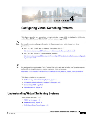
Chapter 4Configuring Virtual Switching SystemsUnderstanding Virtual Switching SystemsNote mls ipx mls netflow mls rp mls switching no shutdownThe mls qos command is not available when a port is in VSL restricted mode.Multichassis EtherChannelAn EtherChannel (also known as a port channel) is a collection of two or more physical links thatcombine to form one logical link. Layer 2 protocols operate on the EtherChannel as a single logicalentity.A multichassis EtherChannel (MEC) is a port channel that spans the two chassis of a VSS. The accessswitch views the MEC as a standard port channel. See Figure 4-4.The VSS supports a maximum of 512 EtherChannels. This limit applies to the combined total of regularEtherChannels and MECs. Because VSL requires two EtherChannel numbers (one for each chassis),there are 510 user-configurable EtherChannels. If an installed service module uses an internalEtherChannel, that EtherChannel will be included in the total.NoteFor releases earlier than Cisco IOS Release 12.2(33)SXI, the maximum number of EtherChannels is 128,allowing 126 user-configurable EtherChannels.Figure 4-4VSS with MECVSLChassis 1Chassis 2181323MECCisco IOS Software Configuration Guide, Release 12.2SXOL-13013-064-5
Chapter 4Configuring Virtual Switching SystemsUnderstanding Virtual Switching SystemsVSS FunctionalityThe following sections describe the main functionality of a VSS: Redundancy and High Availability, page 4-6 Packet Handling, page 4-6 System Management, page 4-6 VSS Quad-Sup Uplink Forwarding, page 4-7 Interface Naming Convention, page 4-8 Software Features, page 4-8Redundancy and High AvailabilityIn a VSS, supervisor engine redundancy operates between the VSS active and VSS standby chassis,using stateful switchover (SSO) and nonstop forwarding (NSF). The peer chassis exchange configurationand state information across the VSL and the VSS standby supervisor engine runs in hot VSS standbymode.The VSS standby chassis monitors the VSS active chassis using the VSL. If it detects failure, the VSSstandby chassis initiates a switchover and takes on the VSS active role. When the failed chassis recovers,it takes on the VSS standby role.If the VSL fails completely, the VSS standby chassis assumes that the VSS active chassis has failed, andinitiates a switchover. After the switchover, if both chassis are VSS active, the dual-active detectionfeature detects this condition and initiates recovery action. For additional information about dual-activedetection, see the “Dual-Active Detection” section on page 4-22.Packet HandlingThe VSS active supervisor engine runs the Layer 2 and Layer 3 protocols and features for the VSS andmanages the DFC modules for both chassis.The VSS uses VSL to communicate protocol and system information between the peer chassis and tocarry data traffic between the chassis when required.Both chassis perform packet forwarding for ingress traffic on their interfaces. If possible, ingress trafficis forwarded to an outgoing interface on the same chassis to minimize data traffic that must traverse theVSL.Because the VSS standby chassis is actively forwarding traffic, the VSS active supervisor enginedistributes updates to the VSS standby supervisor engine PFC and all VSS standby chassis DFCs.System ManagementThe VSS active supervisor engine acts as a single point of control for the VSS. For example, the VSSactive supervisor engine handles OIR of switching modules on both chassis. The VSS active supervisorengine uses VSL to send messages to and from local ports on the VSS standby chassis.The command console on the VSS active supervisor engine is used to control both chassis. In virtualswitch mode, the command console on the VSS standby supervisor engine blocks attempts to enterconfiguration mode.The VSS standby chassis runs a subset of system management tasks. For example, the VSS standbychassis handles its own power management.Cisco IOS Software Configuration Guide, Release 12.2SX4-6OL-13013-06
Chapter 4Configuring Virtual Switching SystemsUnderstanding Virtual Switching SystemsVSS Quad-Sup Uplink ForwardingWhen you use VSS quad-supervisor uplink forwarding, the in-chassis standby (ICS) supervisor engineacts as a DFC line card. Only one processor, the SP processor, acts as the DFC line card; the RP processoris reset to ROMMON. During the bootup, once the chassis level role is resolved, the ICS downloads theimage from the in-chassis active (ICA) supervisor engine. Once the supervisor engine is booted with theimage, it will function in the same way as a DFC line card. All applications running in virtual switch(VS) view the in-chassis standby as a DFC line card.See Figure 4-6 for the various roles that supervisor engines can assume within a quad-supervisor VSSsystem.Figure 4-5Typical VSS Quad-Supervisor ConfigurationSupervisor 2:standby, ICASupervisor 3 ICSSupervisor 4 ICSLinecard 1Linecard 1Linecard 2Linecard 2Linecard NActive chassisLinecard N197277VSLSupervisor 1:active, ICAStandby chassisIf your supervisor engine is: in-chassis active, it can be VSS active or VSS standby. in-chassis standby, it can only be an ICS. VSS active, it can only be ICA. VSS standby, it can only be ICA.Quad-supervisor uplink forwarding provides these key features: eFSU upgrades— You can upgrade or downgrade your VSS system using ISSU. See “Upgrading aVSS” section on page 4-54 for more information about eFSU upgrades. Image version mismatch—Before the bootup, the ICS completes a version check. If there is aversion mismatch, the ICS is set to ROMMON. If you want to boot different images on the ICS andICA. You need to configure the no switch virtual in-chassis standby bootup versionmismatch-check command. This command is only valid once all four supervisors are runningsoftware that supports Quad-supervisor uplink forwarding. If one supervisor is running software thatdoes not support Quad-supervisor uplink forwarding the command will have no effect. EARL mode mismatch—If the supervisor engine EARL modes do not match then the supervisorengine is reset to ROMMON. It is recommended that all four supervisor engines run the same EARLLite or EARL Heavy version. VSS RPR switchover—On RPR switchover the ICS will be reset. For more information regardingRPR see “RPR and SSO Redundancy” section on page 4-12.Cisco IOS Software Configuration Guide, Release 12.2SXOL-13013-064-7
Chapter 4Configuring Virtual Switching SystemsUnderstanding Virtual Switching Systems In-chassis RPR switchover—ICS supervisor engines in the supervisor engine 1 and supervisorengine 2 positions boot up as RPR-Warm. RPR-Warm is when a supervisor engine acts as a DFC.When a VSS stateful switchover occurs, the supervisor engine is reset to ROMMON and boot upswith the supervisor engine image. You can verify the switchover mode of the supervisor engines byentering the show module command. VSS stateful switchover—When the in-chassis active supervisor engine crashes, a switchover occursand the whole chassis reloads (including the ICS) during which the standby supervisor engine takesover as the in-chassis active supervisor engine. A z-switchover operates exactly like a switchoverexcept that the ICS supervisor engine takes priority and is assigned the in-chassis standby supervisorengine. You can initiate a z-switchover by entering the redundancy force switchover command onthe in-chassis active supervisor engine. You can verify the switchover mode of the supervisorengines by entering the show module command.If you insert a supervisor engine from another system (VS or standalone) in the supervisor engine 1 orsupervisor engine 2 position of your existing two supervisor engine VSS system, the supervisor enginedoes a reset to update the supervisor engine number, and then reboots before going online as a DFC.Interface Naming ConventionIn VSS mode, interfaces are specified using the switch number (in addition to slot and port), because thesame slot numbers are used on both chassis. For example, the interface 1/5/4 command specifies port 4of the switching module in slot 5 of switch 1. The interface 2/5/4 command specifies port 4 on theswitching module in slot 5 of switch 2.Software FeaturesWith some exceptions, the VSS has feature parity with the standalone Catalyst 6500 series switch. Majorexceptions include: In software releases earlier than Cisco IOS Release 12.2(33)SXI2, the VSS does not support IPv6unicast or MPLS. In software releases earlier than Cisco IOS Release 12.2(33)SXI, port-based QoS and port ACLs(PACLs) are supported only on Layer 2 single-chassis or multichassis EtherChannel (MEC) links.Beginning with Cisco IOS Release 12.2(33)SXI, port-based QoS and PACLs can be applied to anyphysical port in the VSS, excluding ports in the VSL. PACLs can be applied to no more than 2046ports in the VSS. In software releases earlier than Cisco IOS Release 12.2(33)SXI4, the VSS does not supportsupervisor engine redundancy within a chassis. Starting in Cisco IOS Release 12.2(33)SXI4, the VSS does support supervisor engine redundancywithin a chassis. In releases earlier than Release 12.2(33) SXH2, the VSS feature and the lawful intercept featurecannot be configured together. (CSCsl77715)Hardware RequirementsThe following sections describe the hardware requirements of a VSS: Chassis and Modules, page 4-9 VSL Hardware Requirements, page 4-9 PFC, DFC, and CFC Requirements, page 4-10Cisco IOS Software Configuration Guide, Release 12.2SX4-8OL-13013-06
Chapter 4Configuring Virtual Switching SystemsUnderstanding Virtual Switching Systems Multichassis EtherChannel Requirements, page 4-10 Service Module Support, page 4-10Chassis and ModulesTable 4-1 describes the hardware requirements for the VSS chassis and modules.Table 4-1VSS Hardware RequirementsHardwareChassisCount Requirements2The VSS is available on chassis that support VS-S720-10G supervisorengines and WS-X6708-10G switching modules.NoteSupervisor Engines2The two chassis need not be identical.The VSS requires Supervisor Engine 720 with 10-Gigabit Ethernet ports.You must use either two VS-S720-10G-3C or two VS-S720-10G-3CXLsupervisor engine modules.The two supervisor engines must match exactly.Switching Modules2 The VSS requires 67xx series switching modules.The VSS does not support classic, CEF256, or dCEF256 switchingmodules. In virtual switch mode, unsupported switching modules remainpowered off.VSL Hardware RequirementsThe VSL EtherChannel supports only 10-Gigabit Ethernet ports. The 10-Gigabit Ethernet port can belocated on the supervisor engine module or on one of the following switching modules:Note WS-X6708-10G-3C or WS-X6708-10G-3CXL WS-X6716-10G-3C or WS-X6716-10G-3CXL WS-X6716-10T-3C or WS-X6716-10T-3CXL Using the 10-Gigabit Ethernet ports on a WS-X6716-10G switching module in the VSLEtherChannel requires Cisco IOS Release 12.2(33)SXI or a later release. Using the 10-Gigabit Ethernet ports on a WS-X6716-10T switching module in the VSLEtherChannel requires Cisco IOS Release 12.2(33)SXI4 or a later release.We recommend that you use both of the 10-Gigabit Ethernet ports on the supervisor engines to createthe VSL between the two chassis.You can add additional physical links to the VSL EtherChannel by using the 10-Gigabit Ethernet portson WS-X6708-10G, WS-X6716-10G, or WS-X6716-10T switching modules.Cisco IOS Software Configuration Guide, Release 12.2SXOL-13013-064-9
Chapter 4Configuring Virtual Switching SystemsUnderstanding Virtual Switching SystemsNote When using the 10-Gigabit Ethernet ports on the WS-X6716-10G or WS-X6716-10T switchingmodule as VSL links, you must operate the ports in performance, not oversubscription, mode. If youenter the no hw-module switch x slot y oversubscription command to configurenon-oversubscription mode (performance mode), then only ports 1, 5, 9, and 13 are configurable;the other ports on the module are disabled. Port-groups are independent of each other and one, or more, port-groups can operate innon-oversubscribed (1:1) mode (e.g. for VSL) with the 3 unused ports administratively shutdown,while the others can still operate in oversubscribed (4:1) mode.PFC, DFC, and CFC RequirementsThe VSS supports any 67xx series switching module with CFC hardware.The VSS supports DFC3C or DFC3CXL hardware and does not support DFC3A/3B/3BXL hardware.If any switching module in the VSS is provisioned with DFC3C, the whole VSS must operate in PFC3Cmode. If a 67xx series switching module with a DFC3A/3B/3BXL is inserted in the chassis of a VSS,the module will remain unpowered, because VSS supports only DFC3C and DFC3CXL.If the supervisor engines are provisioned with PFC3C, the VSS will automatically operate in 3C mode,even if some of the modules are 3CXL. However, if the supervisor engines are provisioned withPFC3CXL, but some of the modules are 3C, you need to configure the VSS to operate in 3C mode. Theplatform hardware vsl pfc mode pfc3c configuration command sets the system to operate in 3C modeafter the next restart. See the “SSO Dependencies” section on page 4-25 for further details about thiscommand.Multichassis EtherChannel RequirementsPhysical links from any 67xx series switching module can be used to implement a MultichassisEtherChannel (MEC).Service Module SupportVSS mode supports these service modules: Network Analysis Modules (NAM):– WS-SVC-NAM-1– WS-SVC-NAM-2 Application Control Engines (ACE):– ACE10-6500-K9– ACE20-MOD-K9Note Intrusion Detection System Services Module (IDSM): WS-SVC-IDSM2-K9 Wireless Services Module (WiSM): WS-SVC-WISM-1-K9 Firewall Services Module (FWSM): WS-SVC-FWM-1-K9Before deploying a service module in VSS mode, check the service module release notes and ifnecessary, upgrade the service module software.Cisco IOS Software Configuration Guide, Release 12.2SX4-10OL-13013-06
Chapter 4Configuring Virtual Switching SystemsUnderstanding Virtual Switching SystemsUnderstanding VSL TopologyA VSS contains two chassis that communicate using the VSL, which is a special port group.We recommend that you configure both of the 10-Gigabit Ethernet ports on the supervisor engines asVSL ports. Optionally, you can also configure the VSL port group to contain switching module10-Gigabit Ethernet ports. This configuration provides additional VSL capacity. See Figure 4-6 for anexample topology.Figure 4-6VSL Topology ExampleVSLStandbySupervisorLinecard 1Linecard 1Linecard 2Linecard 2Linecard NActive chassisLinecard N181326ActiveSupervisorStandby chassisVSS RedundancyThe following sections describe how redundancy in a VSS supports network high availability: Overview, page 4-11 RPR and SSO Redundancy, page 4-12 Failed Chassis Recovery, page 4-13 VSL Failure, page 4-13 User Actions, page 4-14OverviewA VSS operates stateful switchover (SSO) between the VSS active and VSS standby supervisor engines.Compared to standalone mode, a VSS has the following important differences in its redundancy model: The VSS active and VSS standby supervisor engines are hosted in separate chassis and use the VSLto exchange information. The VSS active supervisor engine controls both chassis of the VSS. The VSS active supervisorengine runs the Layer 2 and Layer 3 control protocols and manages the switching modules on bothchassis. The VSS active and VSS standby chassis both perform data traffic forwarding.If the VSS active supervisor engine fails, the VSS standby supervisor engine initiates a switchover andassumes the VSS active role.Cisco IOS Software Configuration Guide, Release 12.2SXOL-13013-064-11
Chapter 4Configuring Virtual Switching SystemsUnderstanding Virtual Switching SystemsRPR and SSO RedundancyA VSS operates with stateful switchover (SSO) redundancy if it meets the following requirements: Both supervisor engines must be running the same software version. VSL-related configuration in the two chassis must match. PFC mode must match. SSO and nonstop forwarding (NSF) must be configured on each chassis.See the “SSO Dependencies” section on page 4-25 for additional details about the requirements for SSOredundancy on a VSS. See Chapter 6, “Configuring NSF with SSO Supervisor Engine Redundancy” forinformation about configuring SSO and NSF.With SSO redundancy, the VSS standby supervisor engine is always ready to assume control followinga fault on the VSS active supervisor engine. Configuration, forwarding, and state information aresynchronized from the VSS active supervisor engine to the redundant supervisor engine at startup andwhenever changes to the VSS active supervisor engine configuration occur. If a switchover occurs,traffic disruption is minimized.If a VSS does not meet the requirements for SSO redundancy, the VSS will use route processorredundancy (RPR). In RPR mode, the VSS active supervisor engine does not synchronize configurationchanges or state information with the VSS standby. The VSS standby supervisor engine is only partiallyinitialized and the switching modules on the VSS standby supervisor are not powered up. If a switchoveroccurs, the VSS standby supervisor engine completes its initialization and powers up the switchingmodules. Traffic is disrupted for the normal reboot time of the chassis.The VSS normally runs stateful switchover (SSO) between the VSS active and VSS standby supervisorengines (see Figure 4-7). The VSS determines the role of each supervisor engine during initialization.The supervisor engine in the VSS standby chassis runs in hot standby state. The VSS uses the VSL linkto synchronize configuration data from the VSS active to the VSS standby supervisor engine. Also,protocols and features that support high availability synchronize their events and state information to theVSS standby supervisor engine.Figure 4-7Chassis Roles in a VSSVSLStandbySupervisorLinecard 1Linecard 1Linecard 2Linecard 2Linecard NActive chassisLinecard N181326ActiveSupervisorStandby chassisCisco IOS Software Configuration Guide, Release 12.2SX4-12OL-13013-06
Chapter 4Configuring Virtual Switching SystemsUnderstanding Virtual Switching SystemsFailed Chassis RecoveryIf the VSS active chassis or supervisor engine fails, the VSS initiates a stateful switchover (SSO) andthe former VSS standby supervisor engine assumes the VSS active role. The failed chassis performsrecovery action by reloading the supervisor engine.If the VSS standby chassis or supervisor engine fails, no switchover is required. The failed chassisperforms recovery action by reloading the supervisor engine.The VSL links are unavailable while the failed chassis recovers. After the chassis reloads, it becomesthe new VSS standby chassis and the VSS reinitializes the VSL links between the two chassis.The switching modules on the failed chassis are unavailable during recovery, so the VSS operates onlywith the MEC links that terminate on the VSS active chassis. The bandwidth of the VSS is reduced untilthe failed chassis has completed its recovery and become operational again. Any devices that areconnected only to the failed chassis experience an outage.NoteThe VSS may experience a brief data path disruption when the switching modules in the VSS standbychassis become operational after the SSO.After the SSO, much of the processing power of the VSS active supervisor engine is consumed inbringing up a large number of ports simultaneously in the VSS standby chassis. As a result, some linksmight be brought up before the supervisor engine has configured forwarding for the links, causing trafficto those links to be lost until the configuration is complete. This condition is especially disruptive if thelink is an MEC link. Two methods are available to reduce data disruption following an SSO: Beginning in Cisco IOS Release 12.2(33)SXH2, you can configure the VSS to activate non-VSLports in smaller groups over a period of time rather than all ports simultaneously. For informationabout deferring activation of the ports, see the “Configuring Deferred Port Activation During VSSStandby Recovery” section on page 4-44. You can defer the load sharing of the peer switch’s MEC member ports during reestablishment ofthe port connections. See the “Failed Chassis MEC Recovery” section on page 4-16 for details aboutload share deferral.VSL FailureTo ensure fast recovery from VSL failures, fast link notification is enabled in virtual switch mode on allport channel members (including VSL ports) whose hardware supports fast link notification.NoteFast link notification is not compatible with link debounce mechanisms. In virtual switch mode, linkdebounce is disabled on all port channel members.If a single VSL physical link goes down, the VSS adjusts the port group so that the failed link is notselected.If the VSS standby chassis detects complete VSL link failure, it initiates a stateful switchover (SSO). Ifthe VSS active chassis has failed (causing the VSL links to go down), the scenario is chassis failure, asdescribed in the previous section.If only the VSL has failed and the VSS active chassis is still operational, this is a dual-active scenario.The VSS detects that both chassis are operating in VSS active mode and performs recovery action. Seethe “Dual-Active Detection” section on page 4-22 for additional details about the dual-active scenario.Cisco IOS Software Configuration Guide, Release 12.2SXOL-13013-064-13
Chapter 4Configuring Virtual Switching SystemsUnderstanding Virtual Switching SystemsUser ActionsFrom the VSS active chassis command console, you can initiate a VSS switchover or a reload.If you enter the reload command from the command console, the entire VSS performs a reload.To reload only the VSS standby chassis, use redundancy reload peer command.To force a switchover from the VSS active to the VSS standby supervisor engine, use the redundancyforce-switchover command.To reset the VSS standby supervisor engine or to reset both the VSS active and VSS standby supervisorengines, use the redundancy reload shelf command.Multichassis EtherChannelsThese sections describe multichassis EtherChannels (MECs): Overview, page 4-14 MEC Failure Scenarios, page 4-15OverviewA multichassis EtherChannel is an EtherChannel with ports that terminate on both chassis of the VSS(see Figure 4-8). A VSS MEC can connect to any network element that supports EtherChannel (such asa host, server, router, or switch).At the VSS, an MEC is an EtherChannel with additional capability: the VSS balances the load acrossports in each chassis independently. For example, if traffic enters the VSS active chassis, the VSS willselect an MEC link from the VSS active chassis. This MEC capability ensures that data traffic does notunnecessarily traverse the VSL.Each MEC can optionally be configured to support either PAgP or LACP. These protocols run only onthe VSS active chassis. PAgP or LACP control packets destined for an MEC link on the VSS standbychassis are sent across VSL.An MEC can support up to eight VSS active physical links, which can be distributed in any proportionbetween the VSS active and VSS standby chassis.Cisco IOS Software Configuration Guide, Release 12.2SX4-14OL-13013-06
Chapter 4Configuring Virtual Switching SystemsUnderstanding Virtual Switching SystemsFigure 4-8MEC TopologyRouter, switchor serverMECVirtual switchSupervisorengineActive chassisStandby chassis181327SupervisorengineMEC Failure ScenariosWe recommend that you configure the MEC with at least one link to each chassis. This configurationconserves VSL bandwidth (traffic egress link is on the same chassis as the ingress link), and increasesnetwork reliability (if one VSS supervisor engine fails, the MEC is still operational).The following sections describe possible failures and the resulting impacts: Single MEC Link Failure, page 4-15 All MEC Links to the VSS Active Chassis Fail, page 4-15 All MEC Links to the VSS Standby Chassis Fail, page 4-16 All MEC Links Fail, page 4-16 VSS Standby Chassis Failure, page 4-16 VSS Active Chassis Failure, page 4-16 Failed Chassis MEC Recovery, page 4-16Single MEC Link FailureIf a link within the MEC fails (and other links in the MEC are still operational), the M
A VSS combines a pair of Catalyst 6500 series switches into a single network element. The VSS manages the redundant links, which externally act as a single port channel. The VSS simplifies network configuration and operation by reducing the number of Layer 3 routing neighbors and by providing a loop-free Layer 2 topology.