Transcription
White PaperCisco Catalyst 6500 Series VirtualSwitching SystemWhite PaperDecember, 2012 2012 Cisco and/or its affiliates. All rights reserved. This document is Cisco Public Information.Page 1 of 55
ContentsIntroduction . 3Cisco Catalyst 6500 Series Virtual Switching System: An Overview . 3Cisco Catalyst 6500 Series Virtual Switching System Architecture . 3Virtual Switch Link . 7Virtual Switch Link Initialization . 8Hardware and Software Requirements . 10Virtual Switch Link Redundancy . 13Multiple Cisco Virtual Switching System Domains . 15Cisco EtherChannel Concepts . 16Multichassis Cisco EtherChannel Links . 19Virtual Switch Mode . 20Conversion to Virtual Switch Mode . 21Operational Management . 25Console Management . 25Interface Numbering . 26File-System Naming. 26Reloading the Cisco Virtual Switching System and Its Members . 27High Availability . 28Quad-Sup Uplink Forwarding . 29Configuration Synchronization . 33Virtual Switch Priorities and Switch Preemption. 33Virtual Switch Priorities . 33First Hop Redundancy Protocols . 35Detection Mechanisms and Configuration. 41Action Upon Dual-Active Detection . 45Quality of Service . 47VSL as a Congestion Point . 47Control Traffic over VSL . 50Using Supervisor Engine 720-10G VSS 10 Gigabit Ethernet Uplink Ports as VSL Interfaces . 50Applying Policies . 51Policing . 51Aggregate Policing . 51Microflow Policing and User-Based Rate Limiting. 52Access Control Lists . 53Router ACLs . 54VLAN ACLs . 54Port-Based ACLs . 55 2012 Cisco and/or its affiliates. All rights reserved. This document is Cisco Public Information.Page 2 of 55
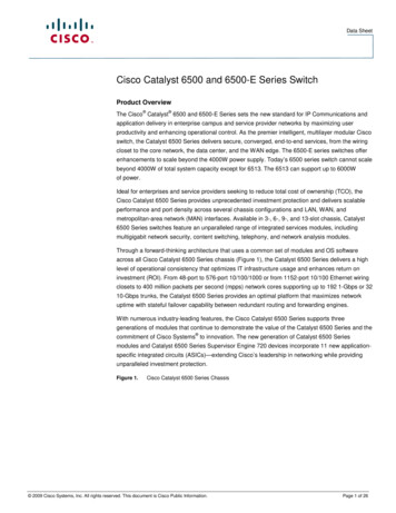
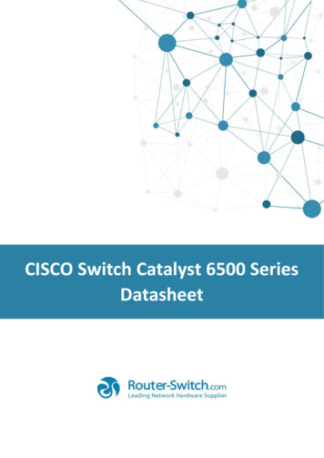
IntroductionThe Cisco Catalyst 6500 Series Virtual Switching System (VSS) allows the clustering of two or more physicalchassis together into a single, logical entity. This technology allows for enhancements in all areas of networkdesign, including high availability, scalability, management, and maintenance.This paper explains the Cisco VSS technology, including its benefits and requirements.Cisco Catalyst 6500 Series Virtual Switching System: An OverviewThe Cisco Catalyst 6500 Series Virtual Switching System (VSS) allows the merging of two physical Cisco Catalyst6500 Series switches together into a single, logically managed entity. Figure 1 graphically represents this concept,where you can manage two Cisco Catalyst 6509 chassis as a single, 18-slot chassis after enabling Cisco VirtualSwitching System.Figure 1.Cisco Virtual Switching System Physical to Logical RepresentationThe Virtual Switching System is created by converting two standalone Catalyst 6500 systems to a Virtual SwitchingSystem. The conversion is a one-time process that requires a few simple configuration steps and a system reload.Once the individual chassis reload, they are converted into the Virtual Switching System.The Virtual Switching System is supported with specific hardware and software components, including theSupervisor Engine 720-10G and the Supervisor Engine 2T.1Cisco Catalyst 6500 Series Virtual Switching System ArchitectureThe Cisco Catalyst 6500 Series Virtual Switching System allows the combination of two switches into a single,logical network entity from the network control plane and management perspectives. It uses Cisco IOS StatefulSwitchover (SSO) technology, as well as Non-Stop Forwarding (NSF) extensions to routing protocols, to provide asingle, logical switching and routing entity. To neighboring devices, the Cisco Virtual Switching System appears asa single, logical switch or router.Within the Cisco Virtual Switching System, one chassis is designated as the active virtual switch, and the other isdesignated as the standby virtual switch. All control plane functions are centrally managed by the active supervisorengine of the active virtual switch chassis, including:1See the “Hardware and Software Requirements” section of this document for details on all VSS hardware and softwarerequirements. 2012 Cisco and/or its affiliates. All rights reserved. This document is Cisco Public Information.Page 3 of 55
Management (Simple Network Management Protocol [SNMP], Telnet, Secure Shell [SSH] Protocol, etc.) Layer 2 Protocols (bridge protocol data units [BPDUs], protocol data units [PDUs], Link Aggregation ControlProtocol [LACP], etc.) Layer 3 Protocols (routing protocols, etc.) Software data pathThe supervisor engine on the active virtual switch is also responsible for programming the hardware forwardinginformation onto all the distributed forwarding cards (DFCs) across the entire Cisco Virtual Switching System. Italso programs the policy feature card (PFC) on the standby virtual switch supervisor engine.Figure 2.Components of Cisco Virtual Switching SystemFrom data-plane and traffic-forwarding perspectives, both switches in the Cisco Catalyst 6500 Series VirtualSwitching System actively forward traffic. The Policy Feature Card (PFC) on the active virtual switch supervisorengine performs central forwarding lookups for all traffic that ingresses the active virtual switch. The PFC on thestandby virtual switch supervisor engine performs central forwarding lookups for all traffic that ingresses thestandby virtual switch. Additionally, all Distributed Forwarding Cards, DFCs across the entire Cisco VirtualSwitching System can also simultaneously perform packet lookups.Centralized ManagementThe fundamental design of a Cisco Catalyst 6500 Series Virtual Switching System allows the centralizedmanagement of all network and device resources. This includes Layer 3 protocols, such as Open Shortest PathFirst [OSPF], Enhanced Interior Gateway Routing Protocol [EIGRP], Border Gateway Protocol [BGP], etc.), as wellas Layer 2 protocols (Spanning Tree Protocol, Unidirectional Link Detection Protocol [UDLD], Flow Control, LACP,etc.). A single supervisor engine in the Cisco Virtual Switching System is elected as the central management pointfor the entire system.The chassis containing the supervisor engine acting as the single management point is referred to as the activevirtual switch. The peer chassis is referred to as the standby virtual switch. The single supervisor engine acting asthe single management point is referred to as the active supervisor engine, and the peer supervisor engine in thestandby virtual switch chassis is referred to as the hot-standby supervisor engine. You can verify this setup with thefollowing commands:vss#show switch virtualSwitch mode: Virtual SwitchVirtual switch domain number: 200Local switch number: 1 2012 Cisco and/or its affiliates. All rights reserved. This document is Cisco Public Information.Page 4 of 55
Local switch operational role: Virtual Switch ActivePeer switch number: 2Peer switch operational role: Virtual Switch StandbyVSS-Sup720#show switch virtual redundancyMy Switch Id 1Peer Switch Id 2Last switchover reason noneConfigured Redundancy Mode ssoOperating Redundancy Mode ssoSwitch 1 Slot 6 Processor --------Current Software state ACTIVEUptime in current state 6 weeks, 5 days, 16 hours, 19 minutesImage Version Cisco IOS Software, s72033 rp Software(s72033 rp-ADVIPSERVICESK9 WAN DBG-M), Version 12.2(33.0.6)SXJ gdb ENGINEERINGWEEKLY BUILD, synced to sierra SIERRA INTEG 110521Copyright (c) 1986-2011 by Cisco Systems, Inc.Compiled Sat 25-Jun-11 00:35 by integBOOT sup-bootdisk:s72033-advipservicesk9 wan dbgmz.122-33.0.6.SXJ gdb,1;CONFIG FILE BOOTLDR Configuration register 0x2102Fabric State ACTIVEControl Plane State ACTIVESwitch 2 Slot 6 Processor --------Current Software state STANDBY HOT (switchover target)Uptime in current state 6 weeks, 5 days, 16 hours, 15 minutesImage Version Cisco IOS Software, s72033 rp Software(s72033 rp-ADVIPSERVICESK9 WAN DBG-M), Version 12.2(33.0.6)SXJ gdb ENGINEERINGWEEKLY BUILD, synced to sierra SIERRA INTEG 110521Copyright (c) 1986-2011 by Cisco Systems, Inc.Compiled Sat 25-Jun-11 00:35 by integBOOT sup-bootdisk:s72033-advipservicesk9 wan dbgmz.122-33.0.6.SXJ gdb,1;CONFIG FILE BOOTLDR Configuration register 0x2102Fabric State ACTIVEControl Plane State STANDBY 2012 Cisco and/or its affiliates. All rights reserved. This document is Cisco Public Information.Page 5 of 55
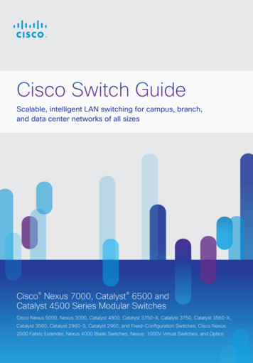
Router MAC AddressesWhen a virtual switch boots up and transitions to an active state, it assigns all its Layer 3 interfaces with a MACaddress. From a default configuration, the MAC address is derived from an EEPROM memory device located onthe Catalyst 6500 chassis itself. Whichever supervisor is elected to the active role will provide the system MACaddress for the VSS. The EEPROM is programmed in the factory and contains range of unique MAC addresses.When the standby virtual switch is brought online after VSL activation, it also derives its router MAC addressesfrom the MAC EEPROM of the active virtual switch. From this point onward, even if a switchover occurs betweenthe virtual switches (causing a role change), the MAC address remains consistent (Figure 3). In other words, thevirtual switch will change its router MAC address after a supervisor switchover event.Figure 3.MAC Address Synchronization Across Cisco Virtual Switching SystemIf the entire Cisco Virtual Switching System is restarted and brought online again, but the peer switch assumes theactive virtual switch role on activation, the router MAC address will then be derived from the peer switch.Consequently, the router MAC addresses will be different from before the system reload. In most environments,this change does not represent a problem, because gratuitous Address Resolution Protocol (ARP) framesadvertising the new router MAC addresses are transmitted upon interface initialization.To avoid reliance on gratuitous ARP for advertising the router MAC address, alternative methods have beendeveloped. The first option is called “Virtual MAC Address.” Using the Virtual MAC Address feature, the routerMAC address will be derived from a formula that uses the domain-id of the VSS pairs, combining MAC addressfrom a pool of MAC addresses dedicated just for VSS. This helps ensure that the router MAC address is unique fora virtual switch domain and will remain the same, irrespective of which becomes active. The Virtual MAC addressfeature is available with Supervisor Engine 720-10G implementations, beginning with software release12.2(33)SXH1, and is available with all software releases for the Supervisor Engine 2T.Example Virtual MAC Address configurationVSS(config-vs-domain)# switch virtual domain 100VSS(config-vs-domain)# mac-address use-virtualVSS (config-vs-domain)#mac-address use-virtualConfigured Router mac address (0008.e3ff.fd34) is different from operationalvalue (0013.5f48.fe40). Change will take effect after the configuration is savedand the entire Virtual Switching System (Active and Standby) is reloaded.VSS(config-vs-domain)#As a best practice when using the Virtual MAC Address feature, it is recommend to always use a unique VirtualSwitch Domain IDs for every VSS in a given network. This helps ensure a unique virtual MAC address for eachsystem. 2012 Cisco and/or its affiliates. All rights reserved. This document is Cisco Public Information.Page 6 of 55
Virtual Switch LinkThe Cisco Catalyst 6500 Series Virtual Switching System consists of two Cisco Catalyst 6500 chassis. In order tobond the two chassis together into a single, logical node, special signaling and control information must beexchanged between the two chassis in a timely manner. To facilitate this information exchange, a dedicated link isused to transfer both data and control traffic between the peer chassis. This link is referred to as the virtual switchlink (VSL).The VSL, formed as a Cisco EtherChannel interface, can comprise links ranging from one to eight physicalmember ports. These links carry two types of traffic: the Cisco Virtual Switching System control traffic and normaldata traffic.To make sure that control traffic gets highest priority across the VSL, a special bit is set on all VSL control frames.This helps ensure that these frames always get priority service from both ingress and egress hardware queues.From a data-plane perspective, the VSL is used to extend the internal chassis data path to the neighboringchassis. Data traffic sent on the VSL is load-balanced, using the configured Cisco EtherChannel load-balancingalgorithms.All frames that are sent across the VSL are encapsulated with a virtual switch header (VSH), which is appended tothe frame by the egress port application-specific integrated circuit (ASIC) and striped off on the other side of theVSL by the ingress port ASIC. The VSH carries information such as the ingress port index, destination port index,VLAN, class of service (CoS), etc. The size of the VSH is the same as that of the internal compact header used bythe Cisco Catalyst 6500; it is 32 bytes long. This header is placed after the Ethernet preamble and directly beforethe Layer 2 header.Figure 4.Virtual Switch HeaderVSL InitializationThe VSS initialization process must determine which supervisor engine will become the active supervisor for theVSS. In order to determine the supervisor active and standby roles, the VSL must be initialized and brought onlinefor control plane communication. Because this determination affects the behavior of each switch, the roles must benegotiated very early during the chassis bootup cycle. As a result, the system must bring the VSL and itsassociated ports online before initializing the rest of the system.Communication between the two chassis is facilitated with internal messaging that is sent across the VSL.Because the VSL is implemented as a Cisco EtherChannel interface, it is resilient to single-link failures. 2012 Cisco and/or its affiliates. All rights reserved. This document is Cisco Public Information.Page 7 of 55
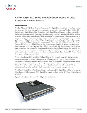
Virtual Switch Link InitializationThe system must bring the VSL online before activating the Cisco Virtual Switching System. The initializationsequence consists of the following steps:Figure 5. VSL InitializationVSL initializationThe supervisor CPU determines which ports local to its chassis form members of the VSL, the configurationfile is preparsed to extract the appropriate VSL commands and their associated interfaces. This way, themodules containing these interfaces can be powered up, and VSL interfaces brought online.The Link Management Protocol (LMP) operates on each link of the VSL and is part of the Virtual SwitchLink Protocol (VSLP). The LMP performs the following functions: Verifies link integrity by establishing bidirection traffic forwarding, and rejects any unidirectional links Exchanges switch IDs between the two chassis Exchanges other information required to establish communication between the two chassis VSS role resolutionThe redundancy role of each supervisor engine is resolved by VSLP. The Role Resolution Protocol (RRP),performs the following functions: Determines whether the hardware and software versions allow a Cisco Virtual Switching System to beformed Determines which chassis will become the active virtual switch and which will become the standby virtualswitch chassis from a control-plane perspective. High-availability role determinationAfter the role resolution, the active and standby image versions and configurations are checked for compatibility.This helps ensure that the hardware and software versions are the same on both chassis supervisor engines. Theconfiguration check makes sure that the VSL-related configurations on the two switches are compatible. If either ofthe two checks fails, then the standby chassis comes up in route-processor redundancy (RPR) mode, where allmodules are powered down, as opposed to Nonstop Forwarding/Stateful Switchover (NSF/SSO) mode, where thestandby chassis is fully initialized and can forward traffic. 2012 Cisco and/or its affiliates. All rights reserved. This document is Cisco Public Information.Page 8 of 55
An example of how configuration checking may force the system into RPR mode is provided in the following output:*Jun 29 14:05:44.731: %VSLP-SW2 SP-5-RRP ROLE RESOLVED: Role resolved as ACTIVEby VSLP*Jun 29 14:05:44.735: %VSL-SW2 SP-5-VSL CNTRL LINK: vsl new control link NEW VSLControl Link 5/4*Jun 29 14:05:44.735: %VSL-SW2 SP-2-VSL STATUS: VSL is UP*Jun 29 14:08:22.294: %VS PARSE-3-CONFIG MISMATCH: The system:/running-config VSLconfig comparison failedSwitch 2 has the following configs that mismatch with Switch 1:Interface TenGigabitEthernet1/5/4 shutdown*Jun 29 14:08:22.210: SW2 SP: VS PARSE DBG ERR: vs redun send check vs config:icc req resp timeout and success: Failed*Jun 29 14:08:22.210: SW2 SP: VS PARSE DBG: vs redun check vs config: runningconfig check on rp not ok*Jun 29 14:08:22.218: %PFREDUN-SW2 SP-6-ACTIVE: Standby initializing for RPR modeThis output shows that the configuration consistency check failed because of a mismatch in the VSL configurationbetween Switch 1 and Switch 2. In this case, Switch 2 has an extra “shutdown” statement under one of its VSLmembers, whereas Switch 1 does not, forcing the standby virtual switch (in this case, Switch 1) into RPR mode.In order to recover from this situation, make the necessary changes to the configuration, save the configuration,and reload the standby chassis:vss#conf tEnter configuration commands, one per line. End with CNTL/Z.vss(config)#int te1/5/4vss(config-if)#no shutvss(config-if)# Zvss#wrBuilding configuration.*Jun 29 14:28:53.906: %SYS-5-CONFIG I: Configured from console by console*Jun 29 14:29:04.834: %PFINIT-SW2 SP-5-CONFIG SYNC: Sync’ing the startupconfiguration to the standby Router. [OK]vss#redundancy reload shelf 1Reload the entire remote shelf[confirm]Preparing to reload remote shelfUpon reload of Switch 1, configurations are now synchronized and both switches can enter into NSF/SSO mode:*Jun 29 14:40:46.101: VS PARSE DBG: vsl mgr parse config file:vsl mgr parse config file:Open Succeeded for running config system:/runningconfig*Jun 29 14:40:46.029: SW2 SP: VS PARSE DBG: vs redun check vs config: runningconfig check on rp ok*Jun 29 14:40:46.037: %PFREDUN-SW2 SP-6-ACTIVE: Standby initializing for SSO mode*Jun 29 14:40:49.874: %PFINIT-SW2 SP-5-CONFIG SYNC: Sync’ing the startupconfiguration to the standby Router. 2012 Cisco and/or its affiliates. All rights reserved. This document is Cisco Public Information.Page 9 of 55
Hardware and Software RequirementsThe Virtual Switching System supports a specific subset of hardware compared to what is supported in astandalone configuration or non-VSS configuration. Therefore it is important to understand these requirementswhen planning the configuration of a VSS.Supervisor EnginesThe initial release of the Virtual Switching System on the Cisco Catalyst 6500 was in January 2008, with theSupervisor Engine 720-10G. In 2011, the Supervisor Engine 2T was released, which also supports VSS.Each supervisor engine is available in two different forwarding configurations, XL and non-XL. The XL configurationprovides higher capacity hardware forwarding tables and forwarding engine-related resources. Therefore, there area total four different supervisor engine model numbers capable of supporting VSS. These are based on theSupervisor Engine 2T and the Supervisor Engine 720-10G.The four Supervisor Engine Model Numbers supporting VSS 0G-3CXLTable 1.*VSS Capable Supervisor ComparisonSupervisor Engine/FeatureVS-S2T-10GVS-S2T-10G -XLVS-S720-10G-3CVS-S720-10G-3CXLRoutes256K (IPv4)1024K (IPv4)256K (IPv4)1024K (IPv4)128K (IPv6)512K (IPv6)128K (IPv6)512K (IPv6)IPv4 Forwarding RateIn hardware; up to 720Mpps*In hardware; up to 720Mpps*In hardware; up to 450Mpps*In hardware; up to 450Mpps*IPv6 Forwarding RateIn hardware; up to 390Mpps*In hardware; up to 390Mpps*In hardware; up to 225Mpps*In hardware; up to 225Mpps*Switch Fabric Capacity2 Tbps (80 Gbps per slotincluding the 6513-Echassis)2 Tbps (80 Gbps per slot inall chassis including the6513-E chassis)720 Gbps (40 Gbps perslot in all chassis exceptthe 6513 and 6513-E)720 Gbps (40 Gbps perslot in all chassis exceptthe 6513 and 6513-E)MPLSLayer 3 VPNs andEoMPLS tunneling. Up to8192 VRFs with a total ofup to 256K* forwardingentries per system.Layer 3 VPNs andEoMPLS tunneling. Up to8192 VRFs with a total ofup to 1024K* forwardingentries per system.Layer 3 VPNs andEoMPLS tunneling. Up to1024 VRFs with a total ofup to 256K* forwardingentries per system.Layer 3 VPNs andEoMPLS tunneling. Up to1024 VRFs with a total ofup to 1024K* forwardingentries per system.VPLSAny Ethernet LAN port inhardware (up to 390Mpps**)Any Ethernet LAN port inhardware (up to 390Mpps**)Supported with SIP andSPA modulesSupported with SIP andSPA modulesNetFlow Entries512 K1024 K128 K256 KLayer-3 classificationand marking accesscontrol entries (ACEs)64 K shared forQOS/Security256 K shared forQOS/Security32 K QoS entries32 K Security entries32 K QoS entries32 K Security entriesChassis Supported6500 E-series chassis only6500 E-series chassis only6500 E-series and 6500non E-series6500 E-series and 6500non E-seriesRequires fully populated 6513-E chassis with DFC-enabled line cards 2012 Cisco and/or its affiliates. All rights reserved. This document is Cisco Public Information.Page 10 of 55
Forwarding EngineThe Cisco Catalyst 6500 can be configured with a single centralized forwarding engine. In this case, the PolicyFeature Card (PFC) is the sole forwarding engine for the system.Optionally, the Cisco Catalyst 6500 can be configured with distributed forwarding engines to provide higherscalability and performance. In a distributed forwarding configuration, the line cards are populated with theDistributed Forwarding Daughter Cards (DFCs). These forwarding engines perform lookup functions for everyframe that enters into the system, and determine the ultimate destination of the packet. They also provide valueadded services, such as security access control list (ACL) and quality of service (QoS) lookups.A Cisco Virtual Switching System-enabled Cisco Catalyst 6500 has two notable differences compared to astandalone Cisco Catalyst 6500 system. First, both the active and the hot-standby supervisor engine PFCs areactive, and are used to perform packet lookups for centralized lookups on each chassis. Second, all forwardingengines are able to support an increased amount of port index information to be able to address a fully populatedCisco Virtual Switching System-enabled chassis. In other words, a port index is now defined using the switchnumber, in addition to the slot and port number.The Supervisor Engine 720-10G Policy Feature Card 3C/XL (PFC3C), as well as the Supervisor Engine 2T PolicyFeature Card 4/XL (PFC4) forwarding engines, are capable of supporting the additional port indices, as well as theactive-active forwarding configuration.System PFC Operating ModeThe system PFC operating mode determines the overall forwarding engine mode for the system. It includes boththe version and the type; for example, a Version 3 or Version 4 PFC, or a type XL or non-XL. The PFC versionindicates specific architectural implementations with support for a specific forwarding performance level and featuresets. The version type indicates the size and capacity of different hardware resources, including the size of the L2and L3 forwarding tables, Access Control List entries and related resources, and NetFlow table resources.The VSS requires that the system PFC operating mode is in PFC3C or PFC4; a mix of PFC3 and PFC4 forwardingengines is not supported. The differences between the PFC3 and PFC4 forwarding engines are significant enoughthat a compatibility mode is not supported. However, one can operate with a mix of non-XL and XL versions, aslong as the forwarding engines are all PFC3 or all PFC4.In the case of the Supervisor Engine 720-10G, there are additional versions of the PFC3 forwarding engine,including the PFC3A and PFC3B. Again, the VSS requires the PFC3C mode or above. If a lower-mode modulewas previously inserted into the chassis that forced the system mode of operation to PFC3A, PFC3B, or PFC3BXLmode, then the Cisco Virtual Switching System function will not be enabled on the system. Likewise, if a modulewith a lower-mode DFC is inserted into the chassis after conversion to Cisco Virtual Switching System mode, thesystem will not grant power to the module.You can verify the PFC operating mode of the system with the following command:Example for Sup720-10GE:vss#show platform hardware pfc modePFC operating mode : PFC3CConfigured PFC operating mode : None 2012 Cisco and/or its affiliates. All rights reserved. This document is Cisco Public Information.Page 11 of 55
Example for Sup2T:vss#show platform hardware pfc modePFC operating mode : PFC4Configured PFC operating mode : NoneAdditionally, as an optional configuration, the supervisor engines of both chassis may prenegotiate their modes tobe in XL-mode or non-XL-mode. This is useful if one wants to help ensure that a VSS running in PFC3C-XL orPFC4-XL mode will not negotiate to a non-XL mode in the event a non-XL line card is inserted into the system.Example for configuring PFC4 non-XL mode on Sup2Tvss#platform hardware vsl pfc mode non-XLIn VSS mode, system EARL mode will be forced to non-XL on next bootupVirtual Switch Link-Capable InterfacesVSL-capable interfaces are required to create a VSL port
value (0013.5f48.fe40). Change will take effect after the configuration is saved and the entire Virtual Switching System (Active and Standby) is reloaded. VSS(config-vs-domain)# As a best practice when using the Virtual MAC Address feature, it is recommend to always use a unique Virtual Switch Domain IDs for every VSS in a given network.