Transcription
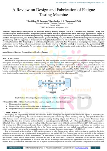
2018 IJNRD Volume 3, Issue 5 May 2018 ISSN: 2456-4184 A Review on Design and Fabrication of FatigueTesting Machine1Shashidhar M Banavasi, 2 Ravishankar K S, 3 Padmayya S Naik1Research Scholar, 2 Assistant Professor, 3 Professor1Dep of MME1N.I.T.K- Surathkal, Mangalore, IndiaAbstract-- Simpler Design arrangement was used and Rotating Bending Fatigue Test (R.B.F) machine was fabricated using localavailability of raw materials to make design arrangement simpler, due of its higher market Price. The design approach was simpler inconstruction .Power was transmitted though vertically arranged pulley arrangement where it is further transferred to load transmittingmembers through universal joint. Rotating Mandrel for specimen holding , was press fitted inside the two bearings which are separatedapart. Bearing Hub was supported on horizontal lever through bolted connection at either side .One end of Lever is hinged and supportedon vertical structure. This design helped in understanding Dynamic scatter and their Prevention on these fatigue machines. FrequentMaintenance showed better performance for longer runs. Scatter observed in Machine can help to overcome by the operator itself. Thisdesign made a better understanding for correlation with experiment results. Experimental results performed on steel showed acceptableresults.Index Terms--- Machine, Design , Forces, Members, Fatigue1 INTRODUCTIONPrevention of fatigue failure in structural members has been an important concern in automotive industrial and aircraft engineering formany years. Technological developments continually bring out new materials, new fabrication processes, improved design concepts, andadditional information about service requirements. Hence, engineering procedures for prevention of fatigue need continual review. Theinitial investigations into this phenomenon was conducted by August Wohler (1819-1914) [2]. A detailed overview is also given by W.Weibull [1]. The first design constitutes the classical high-speed fatigue machine, introduced by Wohler (1871) four point loading rotatingbending specimen.[2]. Stringent safety requirements are common in structural design. A design‐by‐reliability approach is required in evermore situations and accurate design inputs are needed to meet reliability targets while reducing costs [8].Fig 1 Method of loading and general arrangement of Moore Rotating Bending Fatigue Test Apparatus [9].FINK and HEMPEL (1951) (1953) found that the accuracy depends upon three different factors [1] The design of the machine The use of the machine and resulting wear in the bearings The proper manipulation of the machine according to established instructions2 RESEARCH GAPIn designing the fatigue testing machine, we considered that all frame parts are required to be durable and capable of transmitting thenecessary forces and performing the necessary motions efficiently and economically without interfering with any other part of the machine[18]. Various number of Industries/author has designed rotating bending fatigue from Wohler to todays Instron .Numerous designmodification has been done by various author/ industries to make design simpler [28,30,31,44,45] , Dual spindle additional performance type[25] ,High Speed [32], Combined mode of loading [33] ,efficiency improvement [31] and economical Machine [27] .Indeed, according to[4], in fatigue tests different sources of scatter should be taken into account simultaneously scatter related to, to fatigue test conditions (e.g.,test rig) [5,6].Variation of experimental results due to the Fatigue machine scatter has been studied under different mode of loading (uniaxial,3 point,4 point ) test set up by various author mostly using electrical Resistance strain gauges [1,21,22,23,24].Due to the dynamic action involved in RBF machine compared to other fatigue set up, a lesser study was done on modifying the designwith simpler arrangement and lack of dynamic scatter calibration was studied [1] .Even fatigue testing machines available in the market areof high cost and complicated in design arrangements. The uncertainty with respect to the scatter of fatigue testing machines has meant that inspecial cases, where several fatigue testing machines are used in the same study, a statistical comparison of the machines has to beconducted. Laboratory experimentation is a critical final link for a thorough understanding and appreciation of scientific and engineeringtheories. Every possible effort should be made not to deprive the future engineers or educators from this vital component of their educationIJNRD1805002International Journal of Novel Research and Development (www.ijnrd.org)5
2018 IJNRD Volume 3, Issue 5 May 2018 ISSN: 2456-4184[6] It is therefore necessary to continue development of effective and efficient pedagogical methods and techniques for the engineeringlaboratory experience [7].The idea behind this thesis work is not to provide answers to the unanswered questions, but to tackle the problem from a differentperspective. So here it was planned to design and fabricate a test up at a lower cost, which will help in understanding the problems in a betterway.3 METHODOLGYDesign of Machine elements was procceded by superimposing the Forces and bending moment applied to each element. Design wasbased on strength and rigidity [12,13,14,19]3.1 ObjectiveDesign was carried out keeping all the above objective mentioned below It should be easily operatedMachine be capable of withstanding the above mentioned force torqueIt should transmit energy with lower lossesEasily reapairableDesign should help in overcoming any dynamic scatter in the machine by the operator itselfIt should help in frequent disassembling and assembly.Machine should operate for longer runs without frequent start and stop and monitoringMachine should be economical3.2 Basic Components of Fatigue Testing MachineAny fatigue testing machine is composed of the following structural components [1] Load-producing mechanismLoad-transmitting members such as grips flexural jointsMeasuring devices for revolutionsShut-off apparatusFrame work3.3 General DescriptionThe fatigue-testing machine is of the rotating beam type. The specimen functions as a single beam symmetrically loaded at two points.When rotated one-half revolution the stress in the fibres originally above the neutral axis of the specimen are reversed from compression totension for equal intensity. Upon completing the revolution, the stresses are again reversed, so that during one complete revolution the testspecimen passes through a complete cycle flexural stress.3.4 Planned DesignFront ViewSide ViewTop ViewFig 2 Machine DiagramIJNRD1805002International Journal of Novel Research and Development (www.ijnrd.org)6
2018 IJNRD Volume 3, Issue 5 May 2018 ISSN: 2456-4184Machine parameters taken from Instron fatigue test set up, Model RRM-A2 conidered as reference [9] for our design of machineelements.4 DESIGN ANALSYSMinimum to maximum bending is allowed 25 kg-cm to 230 kg – cm, Maximum applied load 20 kg , Rotational speed 500- 10000 rpmFig 3 Elemental diagram of a material subjected Treating as Bi-Axial loading [11]First divide this complex state of force or stress analysis into a elementary type Torque applied Bending moment due to vertical loadAccording to ASTM E 466-82 [10]Fig 4 Specimen dimensionDg 6.5 mm , Lg minimum 3 times diameter 20 mm ,R minimum 8 times diameter , 8 6.5 60 mm4.1 Design CalculationSuperimposing of applied moment and torque for design of machine elementsIt is assumed that machine would at times be required to test some mild steel and medium strength steel at the stress level in theneighbour of the yield stress.The shear stress theory is reasonably good agreement,it is often used by engineer to obtain quick estimates.Mechanical properties of Steel ,Ultimate strength 400 Mpa, yield strength 240 Mpa, Ӷ Shear Strength 200MpaThe torque required to start yield at the outer fibers of a specimen of such steel is (T)T Ӷ π d3/16(1) 10785.89 N-mm4.2 Design of torque transmitting shafts (d)The torque transmitting shaftd 3 16 t/π Ӷ 11 mmDesign of Power transmission shaft considering fatigue load.Shaft material selected as C30 steel,diameter 10.80mm ,subjected to rotating bending fatigue loading,fatigue factor 1.612AssumingK size 0.85 K surface 0.83 K reliabliity 0.896Seˈ 0.5 σ ultimate 245 mpase k size k surface k reliableity 1/ks se(2) 147.6 Mpa[43].This fatigue strength calculated is less than endurance strength of standard C 30 steel, shows that the design is safe.Power transmission consists of the following arrangements Motor with Standard specification. Stepped pulley arrangement. Leather trapezoidal section V belt to connect motor driver shaft and driven shaft vertically for better stability.IJNRD1805002International Journal of Novel Research and Development (www.ijnrd.org)7
2018 IJNRD Volume 3, Issue 5 May 2018 ISSN: 2456-4184Considering power transmission shaft as beamFig 5 Simply supported beam of shaftYmax FL3/48EI(3) 0.00249 mmE Youngs Modulus N/mm2 , L 40 mm assumedΣΣbendingbending M/z (4) M Moment,z Section Modulus mm 3 79.66 N/mm24.3 Design of motor power required (P)P 2 π n t/60 watts 379.09 watts 0.5 hp(5) n Revoultion4.4 Design of tension acting on the belt (P1,P2 in Newton N )Selecting cast iron stepped cone pulley with a leather belt arrangement having a provision of 3 stepped diameters of larger being125mm,smaller 75 mm and 100 mm respectively.(P1-mv2/P2 –mv2) fα/sin(θ/2) (6)(P1-mv2/P2 –mv2) e(o.35 2.99)/(sin (40/2))For maximum belt tension condition(P1/P2 ) 21.54 the belt tension is maximumP1 P2 21.54Torque T Ft r(7)10785.89 Ft diameter of pulley/2Ft P1 215.27 N (Ft Tangential Force N )P2 215.27 /21.54, P2 9.99 N4.5 Power transmission connection & Purpose of the jointIn order to transmit torque from power transmission system to the specimen through load transmitting member there should be anjoint/connection required to connect these two assemblies. Various mechanical joints are availiable, as we have decided to select useuniversal joint which serve the purpose with better efficiencies which used in smaller automobiles.To connect power transmission system and load transmitting memberIt should transmitt power at different angles (sweiling motion is permitted to load transmitting member when specimen fails)The design up to here ended up with the following dimensions Torque required to shear the specimenDiameter of shaft for mounting pulley assemblyAn approximate distance between the two bearingSafe bending on shaftSafe fatigue enduranceLeft section is consider as weakest compare to rightDesign and selection of Load transmitting members with an simple arrangment to over come Machine scattering plays a vital role in thismachine.4.6 Load-producing MechanismThe loads may be produced by various methods: mechanical, electromagnetic. Load produced by dead weight A machine of this type,however, developed by H. F. Moore and KOMMERS (1927). [1] A constant bending moment is maintained by directly applied static loadsby using weight hanger [41]IJNRD1805002International Journal of Novel Research and Development (www.ijnrd.org)8
2018 IJNRD Volume 3, Issue 5 May 2018 ISSN: 2456-41844.7 Design of load transmitting memberAdvantages of practical use for supported levers in testing machines, which is a simple and effective means of overcoming difficultiesexperienced with the usual type of bearing and knife edges. Since a cross- pivot has no sliding parts there is no need of lubrication. Thedeflection is, however, accompanied by reaction forces, though they are usually very small. This constructional element has been examinedby Eastman (1935).It has been studied experimentally by Young (1944) and theoretically by Haringx (1949). [1]This case can be divided into two sub points: vertical external load 200 N torque transmitted 10785.89 N-mm External load of 200 N and Torque of 10785.89 N-mm will be shared by two mandrel at either side,with two bearings placed a distanceapart and are fitted in hub.F2 & F3 are the forces distrubuted which are acting on top of the bearings including self weights Bearings are placed at a distance Length ofthe mandrel is 80 mmConsidering Horizonatal lever as beamFig 6 Simply supported beam F y 0 ,Rv1 Rv 2 49.5 N m1 0 ,- Rv1 135 24.5 80 24.5 130Rv1 11.38 N, Rv2 38.11 NStatic Deflection of shaftYmax ( -Fba/27EI) (b 2a) ( 3b(b 2a)),At L1 (L2 L3) Lever breadth 25mm,t 15mmYmax 0 .0000683mm is safe4.8 Radial Loads AnalysysRadial force on bearing is when specimen is about to fail after crack propogation.the magnitude of this load will be lesser compare to theexternal loading.Treating load supporting member including specimen as an beam for our analysis, due to symmetry in the structure. considering horizontalexternal forces finding out its reactionRadial thrust assumed as 50NFig 7 Consider an mandrel and load transmitting member assembly arranged as shown aboveConsidering Vertical Force of 50 N by rotating it 90 0 treating as radial horizontal force acting on simply supported beam as shown in fig 7 H 0RH1 11.38 N,RH2 38.11 NConsidering vertical and horizontal reactionsR1 (Rv12) (RH12) , 16.57 N(8)R2 (Rv22) (RH22), 53.89 NConsidering this reaction are acting on bearing from either side of holding memberFr1 76.57 N, Fr2 110.52 NIJNRD1805002International Journal of Novel Research and Development (www.ijnrd.org)9
2018 IJNRD Volume 3, Issue 5 May 2018 ISSN: 2456-4184Expected bearing lifeL10 60nl10h/106(9) 60 1440 8000/106 691.2 million revolutionConsidering load factorC1 p1 (l10)1/3 (load factor),(10) 1656.02 N Load Factor 2.5C2 p2 (l 10)1/3 (load factor), 2390.287 N4.9 Design of bearing lifeThere are two bearing on each mandrel so the load carried by each bearing will be approximately 50 NSelect tapered roller bearing because , during crack propogation in there may be sweiling action of the load transmitting member ,andthere may be load acting in lateral direction also.Expected bearing lifeL10 60nl10h/106, 864 million revolution ,n 1400C p (l10)1/3 , 465 N dynamic loadDynamic load/ cycle 2390.287/106 0.002390 N/CycleConsider uniform form force to all member in each cycle may be assumed as 0.002390 N4.10 Design of Mandrel assembly connection by welding and fasteners arrangementBy knowing the forces acting on the horizontal pivot which is required to hold mandrel assembly, it was planned to have an boltedconnection. Initially it was planned to have 2 bolted connection at each side of lever.Considering an horizontal pivot arrangement with an provision of two holes for bolted connection shown in fig 8Fig 8 Horizontal lever with bolting provisionMaximum external loading is 200 N, Considering the primary and secondary shear forceCenter of gravity lies in between two boltsPermissible shear stressϮ 0.5 Syt/F.S(11) 49 N/mm2Primary shear forceP1 P2 P/2 61.31/2(12) 30.6 NSecondary shear forceP1 P2 ((P e)r1/(r12 r22)) (13) 55.7NResultant shear forceR.S.F P2 P2 (14) 30.6 55.7 86.3 NCore diameter of bolt is given byϮ r.s.f/(area of the bolt)(15)49 (86.3/(π/4 d2))d 2.67 mm diameter of bolt4.11 Design of welded joint required to connect power transmission shaft and load transmitting member through universal joint.Ϯ m /2πtr2(16)140 2513.6/2 π t 12.52t 0.01828 mmH 0.025/0.707A High strength connection is enough to transmit the torque.4.12 Design of vertical structure.There should be a vertical structure in order to with stand the reactions as calculated , on top provided an pin joint connection to the loadtransmitting member through lever.IJNRD1805002International Journal of Novel Research and Development (www.ijnrd.org)10
2018 IJNRD Volume 3, Issue 5 May 2018 ISSN: 2456-41844.13 Design of base structureThe machine base structure decides the volume occupied by the machine. Material selected for construction of base is cast iron L shapedsection [18] as commonly used . Placing horizontally design of load transmitting member, universal joint and power transmitting systemassembly makes an appropriate length of 900 mm, and height of 300 mm, and width of 450mm,where here it is decided to check for saferoperation of machine with lesser vibration and high damping.4.14 Unexpected stresses due to self weightIt is easy to show that in order to limit the error to not more than I per cent of true stress applied to a rectangular specimen of crosssection b x h, the line of load must not deviate from the geometrical axis of the specimen by Nsore than 0-0.002 % h or d (Axial loading) .This problem has been discussed by Morrison (1940) [1] .Considering minimum effective weight of the load transmitting member acting on specimen is 7 kg shown in fig 9Fig 9 Simply supported beamYmax Fl3/48EIL 20 mm assumed 70 403/48 200 103 ((π 6.654)/64)) 0.00437 mm.4.15 Critical speed of the machineAlthough there are many possible causes of vibration in rotating equipment, this technique will deal only with that component of vibration,which occurs at running speed (frequency), and is caused by a mass unbalance in the load transmitting members. The critical speed of thefatigue testing machine design is given by. [12,16]Ω (Ӆ/L)2 (EIg/Ay)(17)Ω Critical Speed Rad/secL Length of the rotating member 110mmI Ӆ/64 d4(18) Ӆ/64* 74 117.874mm2g accleration 9.81m/s2a area of the shafta ( Ӆ/4*d2 ) mm2(19) (Ӆ/4*0 .0072) 3*10-5 m2 ץ ρ L ρ Density kg/m3(20) 7850 * 0.1 785 kg/m2If φ a * ץ (21) 0.00003 * 785 0.02355 kgΩ (Ӆ/L)2 (EIg/φ)(22) (Ӆ/100)2 (200*103 * 117.8*9.81/0.0235) 86.89 Rad/secFirst before continuing the vibration.With L 110m, F 293.44N, I 19174.76mm4 200 x 103Static deflection of the shafting is given byYmax FL3/48EI (200 *1003) / (48*200*103*117.8) 0.176mmFrequency of the transverse vibrationFn 0.4985/(23) 1.20 HzThis is less than the frequency of the rotating speed of the motor. Therefore, the machine is free from much vibration.4.16 Static Calibration and Dynamic Checking of Testing MachinesThe load should be reproduced with sufficient accuracy, and it should be transmitted to the test piece without undue scatter. In machineswhere the load is generated by dead weights and transmitted to the specimen through a lever system, weights and forces have to be carefullycontrolled including weighing of all levers and other parts of the loading system, together with an experimental determination of the centersof gravity of these parts.[1,39,40,41]IJNRD1805002International Journal of Novel Research and Development (www.ijnrd.org)11
2018 IJNRD Volume 3, Issue 5 May 2018 ISSN: 2456-41844.17 2 D Diagram of important machine element5 FABRICATED MACHINEA- Horizontal Lever B- Bearing Housing C- Specimen D- Vertical Rest E- weight hanger F- Universal Joint G- Stepped Pulley H- PowerTransmission Shaft I- Base M- Phase Motor ,P-Pivot6 EXPERIMENTAL RESULTSMaterial Ductile Iron Austempered at 3000CFig 10 S-N CurveIJNRD1805002International Journal of Novel Research and Development (www.ijnrd.org)12
2018 IJNRD Volume 3, Issue 5 May 2018 ISSN: 2456-41847 CONCLUSIONSThe design approach was simple, identifying the critical section of the machine, superimposing of forces and moments, followed designbased on biaxial loading consideration. Choice of design and material selection was done on local avaliability, so any replacement of parts ormachining operations can be done within the workshop itself. Small amount of vibrations was nullified due to the heavy structure and byusing rubber pads on four corner. A provision provided at the pivot assembly is that by knowing the lateral difference in distance betweenthe two horizontal pivots, manual adjustment is made by increasing or decrease in washer thickness with machining accuracy so somemachine scatter (lateral misalignment / Co- Axiality) can be adjusted which showed a better performance in run, due to this rise intemperature effects can be almost nullified. Gripping methods used in this machine showed that loosening of grips during dynamicconditions can be identified by the movement of unscrewing of locking nut from its locked position which was known before. Due to itssymmetry of a load supporting member the choice of design is made such that, use of bolted connection, pin joint and locking its movementby an washer arrangement assembly, will help an operator to easily dismantle the assembly without damage and will help him in calibrationof machines whenever necessary. Initial tightening of fastener arrangement required for better and stable operation. Bearing should belubricated time to time. Simpler Design helped in understanding dynamic scatter in these type of machines. Any misalignments produce inthe system will overcome by operator easily. Machine generates acceptable results.REFERENCES[1] Fatigue Testing Machines and Equipments By Wiebull 1960.[2] Wohler's, Experiments on the Strength of Metals", Engineering, London, Vol. 2, August 23, 1867, P. 160 and Engineering, London, Vol.11, (1871), P. 149.[3] J. Schijve, Fatigue Predictions and Scatter, Fatigue Fract. Eng. Mater. Struct. 17 (1994) 381‐396.[4] F.A. Kandil, B.F. Dyson, The Influence of Load Misalignment during Uniaxial Low‐Cycle Fatigue Testing–I: Modeling, Fatigue Fract.Eng. Mater. Struct. 16 (1993) 509‐527.[5]F.A. Kandil, B.F. Dyson, The Influence of Load Misalignment during Uniaxial Low‐Cycle Fatigue Testing: Applications, FatigueFract. Eng. Mater. Struct. 16 (1993) 529‐537.[6] Sepahpour, B., “Design of an Affordable Model Laboratory for Mechanical and Civil Engineering Programs”, Proceedings of ASEE2003 National Conference, Nashville, Tn, June 2003.[7] Sepahpour, B., Clark, E. And Limberis, L. “Modular Lumped Mass Experiment”, Proceedings of ASEE 2004 National Conference, SaltLake City, Utah, June 2004.[8] Paolino, D.S., Chiandussi, G. And Belingardi, G., 2013. Uncertainty in Fatigue Loading: Consequences on Statistical Evaluation ofReliability in Service. Probabilistic Engineering Mechanics, 33, Pp.”.[9] Www.Instron.Com, Industrial Products Group.[10] Astm E 466-82,Standard Method for Preparation of Rotating Bending Specimen.[11] Design of Machine Elements by V.B.Bhandari,3r dEdition,2013.[12] Gbasouzor Austine Ikechukwu,Okeke Ogochukwu Clementina And Chima Lazarus Onyebuchi., Design and Characterization Of AFatigue Testing Machine, Proceedings of The World Congress on Engineering And Computer Science 2013 Vol I,2013.[13] K Mahadevan, K Balaveera Reddy Design Data Hand Book For Mechanical Engineers, Third Edition,1987.[14] Thomas H Brown,Mark’s Calculation For Machine Design, Mcgraw-Hill,2005.[15] Hugh Jack,Basic Mechanics,1993-2001.[16] K.Nisbett, Dynamic Balancing Of Rotating Machinery Experiment, 1996.[17] Fathy Kandil, Recent Intercomparisons on Low Cycle Fatigue And Alignment Measurements, Technical Working Area 13 Low CycleFatigue,2001.[18] Soon-Bok Lee, Stress Analysis and Design For a Structural Fatigue Testing Machine, Ksme Journal, '101.5, No.2, Pp. 115-124, 1991.[19] Robert C. Juvinall, Kurt M. Marshek, Fundamentals of Machine Component Design, John Wiley & Sons, Inc,2012.[20] ISO Method of Rotating Bar Bending Fatigue Test of Metals,First Revision 1986.[21] J.P. Hessling, Dynamic Calibration of Uni-Axial Material Testing Machines, Mechanical Systems and Signal Processing 22 (2008)451–466.[22] F A Kandil, The Determination Of Uncertainties In Low Cycle Fatigue Testing, Manual of Codes of Practice for The Determination ofUncertainties In Mechanical Tests on Metallic Materials,2000.[23] G.F. Pezzuto, the Determination of Uncertainties In High Cycle Fatigue Testing (For Plain And Notch-Sensitive Specimens), Manual ofCodes of Practice for The Determination of Uncertainties In Mechanical Tests on Metallic Materials,2000.[24 ] G. Dahlberg, Mts Systems Corporation, Eden Prairie, Usa, Dynamic Calibration of Axial Fatigue Testing Machines., EurolabInternational Workshop: Investigation And Verification Of Materials Testing Machines.[25] Taizoh Yamamoto, Akio Kokubu,Tatsuo Sakai ,Yuki Nakamura, Development And Several Additional Performances of Dual-SpindleRotating Bending Fatigue Testing Machine Giga Quad, 13th International Conference On Fracture June 16–21, 2013, Beijing, China.[26] Abdul Quadir, Design and Development of Fully Reversed Axial Loading Fatigue Testing Machine, International Journal of AdvancesIn Engineering & Scientific Research, Volume 1, Issue 3, July-2014, Pp 08-17.[27] K. K. Alaneme, Design of A Cantilever - Type Rotating Bending Fatigue Testing Machine, Journal of Minerals & MaterialsCharacterization & Engineering, Vol. 10, No.11, Pp.1027-1039, 2011.[28] By C. V. Joga Rao And L. S. Srfenath, Design of Low Frequency Fatigue Testing Machines, Jounal of Indian Institute of Science.[29] Junye Li, Jinlong Wang,Weidong Wang, The Design and Numerical Simulation for V-Ribbed Belt Fatigue Tester, Journal ofTheoretical and Applied Information Technology 2012.[30] Bijan Sepahpour, A Practical Educational Fatigue Testing Machine,121 st ASEE Annual Conference and Exposition,Indiana Polis,2014.[31] Yeong-Shu Chen* And Le Hong Chuong, Efficiency Improvement Of The Highly Accelerated Life Testing System By Using MultipleHammers, Journal Of Mechanical Science And Technology 28 (12) (2014) 4815 4831.[32] C. Ghielmetti, R. Ghelichi, M. Guagliano, F. Ripamonti, S. Vezzu, Development of a Fatigue Test Machine for High FrequencyApplications, Procedia Engineering 10 (2011) 2892–2897.[33] E. Zalnezhad & Ahmed A. D. Sarhan & P. Jahanshahi, A New Fretting Fatigue Testing Machine Design, Utilizing Rotating–BendingPrinciple Approach, Int J Adv Manuf Technol (2014) 70:2211–2219.IJNRD1805002International Journal of Novel Research and Development (www.ijnrd.org)13
2018 IJNRD Volume 3, Issue 5 May 2018 ISSN: 2456-4184[34] Brecht Van Hooreweder1(*), David Moens2, Rene Boonen3, Paul Sas4, Design and Implementation of a Fatigue Test Rig forFluctuating Loading In Bending and Torsion, 15th International Conference on Experimental Mechanics,2012.[35] Brecht Van Hooreweder, David Moens, Rene Boonen1, Paul Sas, Accelerated Multi-Axial Fatigue Experiments: Test Rig Design andFirst Results, Proceedings Of Isma2012.[36] İrfan Ay, Raif Sakin, An Improved Design of Apparatus for Multis Pecimen Bending Fatigue and Fatigue Behaviour For LaminatedComposites, Materials And Design , 2008[37] A. Kusab, S. Okazak,, M. Endo, K. Yanase, Designing af a Testing Machine For Shear-Mode Fatigue Crack Growth, AdvancedMaterials Development and Performance, International Journal of Modern Physics, World Scientific Publishing Company.[38] Bruce Boardman, Deere and Company, Technical Center, Fatigue Resistance of Steels, ASM Handbook, Volume 1: Properties andSelection: Irons, Steels and High-Performance Alloys, 1990.[39] Galal S. A. Shawki, "A Review Of Fatigue Testing Machines", Engineering Journal Of Qatar University, Vol. 3, 1990.[40] Vincent R. Lalli, Dimitri Kececioglu, And Jeffrey B. Mcconnell Lewis Research Center, Design Features and Results from FatigueReliability Research Machines, N A S A T e c h n i c a l M e m o r a n d u m,1971.[41] V. R. Lalli, D. Kececioglu And J. B. Mcconnell, Design Features and Results from Fatigue-Reliability-Research Machines,Experimental Mechanics,1971[42] Włodzimierz Będkowski, Assessment of The Fatigue Life of Machine Components Under Service Loading, A Review of SelectedProblems, Journal of Theoretical And Applied Mechanics 52, 2, Pp. 443-458, Warsaw 2014.[43] Libor Trško1,*, Otakar Bokůvka2, František Nový2, Branislav Hadzima1,2, Fatigue Life Analysis of Die Forged Railway AxleManufactured from C30 Steel, Materials Engineering - Materiálové Inžinierstvo 21 (2014) 104-108.[44] L.N. Ojha H.B. Khurasia A.D. Telang, Design And Development of A Reversed Bending Fatigue Testing Equipment for LaboratoryUse, International Conferenceon Shot Peeningand Blast Cleaning.[45] N V Chawan,P G Damle,N K Patil,Design And Manufacturing of Fatigue Test Machine for Tension and Compression Springs,International Journal of Advanced Electronics & Communication Systems,2014.IJNRD1805002International Journal of Novel Research and Development (www.ijnrd.org)14
Abstract-- Simpler Design arrangement was used and Rotating Bending Fatigue Test (R.B.F) machine was fabricated using local . Shaft material selected as C30 steel,diameter 10.80mm ,subjected to rotating bending fatigue loading,fatigue factor 1.612 [43]. Assuming K size 0.85 K surface 0.83 K reliabliity 0.896 S eˈ 0.5 σ ultimate .