Transcription
ME 215CHAPTER 6FATIGUE PROPERTIES OFMATERIALSPART-2Dr. Oğuzhan Yılmaz (Asst.Prof.)http://www.gantep.edu.tr/ oyilmaz
FATIGUE PROCESS STAGESo From the design applications point of view, the mainengineering interest in the fatigue properties lies inthe "high-cycle" region.o However, there are many instances where the socalled “load cycle" is very slow; which makes theemployment of fatigue properties in the low cycleregion feasible to achieve the desired designefficiency.o When only a short service life is required, the lowcycle fatigue data can advantageously be employed
UNIAXIAL FATIGUE STRENGTH UNDER ALTERNATING STRESSThe failure of the railway axles initiated the first orderly approach to thenature of such fatigue failures with alternating stress form.Seeing the inadequancy of the classical approaches, Wöhler designed thefirst ‘rotating bending’ fatigue tester to determine the fatigue strength ofthe axles of the railway cars.
There are different types of fatigue testingmethods/machines regarding the analysis of thefatigue properties of materials1. rotating bending is the most widely used method oftesting2. alternating bending is another type of testingmethod3. axial loading (or push-pull) is the other testingmethod
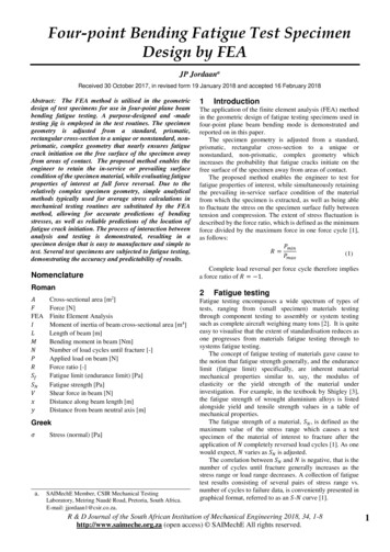
Rotating bending fatigue testerIn this method of testing, a specimen, subjected to a constant bending moment or a constantbending stress by shaping the specimen accordingly is rotated until fracture.Two types of Rotating bending fatigue testers are:o Constant bending moment type (4-Point Bending tester) (fig.a)o Cantilever type (Constant Bending Stress) (fig.b)
Constant bending(4-Point Bending) fatigue tester
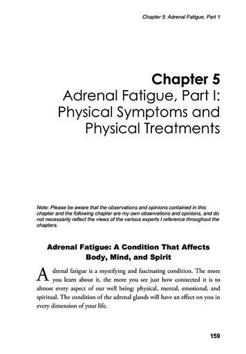
Cantilever type rotating bending fatigue testero In cantilever type rotating bending fatigue testing machines, the bendingmoment varies along the gauge length of the specimen.o Condition of constant stress along the gauge length is satisfied by ‘tapering ’the specimen.
Alternating bending type fatigue testero Other standart method of uniaxial fatigue testing is the alternating bendingtype fatigue testing, where the bending load itself alternates but thespecimen is stationary.
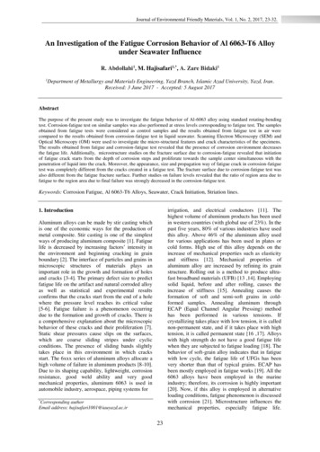
o The axial loading (push-pull) type fatigue tester is the other machine wherespecimen is not exposed to bending but to pure axial (tensile orcopmressive) loading.o Specimen is held at two ends and loaded cyclically between two extreme(max. & min.) values.
The axial loading (push-pull) type fatigue testero The advantage of thesefatigue testers is that theycan also be used to apply amean stress, whereas therotating bending typefatigue testers areexclusively for applyingalternating stress.The axial loading (push-pull)testers, employingconversion attachmentsare also capable of bendingand torsion fatigue testingwhen necessary.
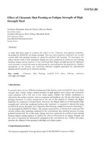
Standart fatigue test specimens for different fatigue tester machines
FATIGUE TEST The main aim of the fatigue testing is the determination of somemechanical properties of the material as in other types of tests liketension, torsion etc . Similar to stress-strain curve of tensile test , another curve isconstructed for the fatigue test of materials and this curve is called the“S-N” curve. On the S-N curve, mechanical properties like fatigue strength,endurance strength, etc. are determined.
S-N curve construction S-N curve of a material is usually constructed by doing multiples ofrotating bending fatigue tests of the material. Each test is represented by a point on the S-N curve.In each test, A specimen is loaded to create a certain level of stress amplitude (Sa)within the material and then the specimen is rotated until itfractures. When the specimen fractures, both the level of stress applied (Sa)and the number of revolutions (cycles, N) to fracture are noted. Multiples of tests at different stress levels (from Su down to very lowstress values) with corresponding cycles to fracture will createmultiples of test points for the construction of S-N curve
S-N Curveo For certain metals and alloys, theS-N curve becomes asymptotic tothe horizontal line. This mean thatthe specimen will not fail for aninfinite number of cycles.o The stress level corresponding tothis asymptote is called the,‘endurance strength’ or ‘thefatigue limit’ of a metal.o Se is the symbol for endurancestrength.
Here is the graph obtained by plotting the values of Sa and N (life) called‘S-N’ curve or ‘Wöhler’ diagram.
INTERPRETATION OF FATIGUE Fatigue is a very complicated phenomenon. It is subjected to many variables and is easily influenced bymany factors. Because, S-N curves are only approximations and representthe fatigue behaviour of laboratory specimens the fatigue lifeof an actual part may vary considerably from the laboratoryresults.The important points about S-N curve are:ooooStatical Nature of FatigueEffect of Surface Quality & TreatmentSize EffectsMethod of Testing
INTERPRETATION OF FATIGUEStatical Nature of Fatigue:- When identical specimens are fatigue tested at same stress level , theirfatigue lives are generally not the same , but may vary or scatter a greatdeal.- Because of the fact that the fatigue life is easily influenced by many variables,the S-N curve represents a statical average of the test results.- In other words, the meaning of the S-N curve, as drawn, is that 50%specimens are expected to fail above this curve and the other 50% belowit. We can see this differences on P-S-N curve on next page.- For different probabilities of failure (or for different reliabilities) a modifyingfactor Mr is used to modify the S-N curveMr 1-0.08.P(see related tables and figures in textbook)
INTERPRETATION OF FATIGUEEffect of Surface Quality:This factor is very important for fatigue failure.In fatigue, crack may start due to microscopic surface irregularties not easlyvisible to naked eye.General rule is that:- Surface roughness decreases, fatigue life increases,- Surface rougness increases, fatigue life decreases
INTERPRETATION OF FATIGUEThe modifying factor Ms is used to modify the fatigue strength of partsmachined with different methods.The surface irregularties are effected by cold working the specimen with moreplastic flow. This then relaxes the stress concentration produced by surfaceirregularies.
INTERPRETATION OF FATIGUEThe residual surface compression produced by some mechanicalfinishes is known to improve the fatigue life because of its retardingeffect on crack propogation.Thus operations like;o Sandblastingo Shot peeningo Burnishing & alike generally improve the fatigue life.On the other hand, the processes likeo Electro polishingo Chem-milling & alikewhich do not produce a compressive layer may reduce the fatigue life.
INTERPRETATION OF FATIGUEGrinding like EDM (electrical discharge machinig) is capableof producing high localized surface temperatures. During aprocess of severe grinding very high localized surfacetemperatures are generated.These hot spots are rapidly quenched by either the bulk ofmaterial or cooling fluid thus producing an unintentional‘heat treated’ layer of non-uniform properties or evencracking.
Like machining, surface treatments which produce a high strength layerwith favourable compressive residual stresses improve the fatigueproperties.Surface compressive stress may be obtained by;– Nitriding– Carburizing– Flame or induction hardening (if properly done)– Drastic quenhing of shallow hardening steel
Size Effects Fatigue properties (or results) will vary with the size of thematerial and this has been proven by experiments (asmentioned in tension tests). The general observation being that the Fatigue strength oflarge parts may be considerably lower than that of the smallspecimens. The phenomenon of the size dependency of the test results iscalled the size effect and it is one of the most importantproblems encountered in fatigue applications.
The materials (with larger sizes) become moreheterogeneous with increasing size; which makes it alltogether impossible to prepare specimens which retainthe nominal properties of the specified material. The usual capacities of the laboratory type testingmachines are also limited to conduct experiments withlarge specimens.
Method of Testing The S-N curves obtained by three methods of testing(altemating bending, rotating bending, and push-pull) differappreciably One can not therefore base the design of a machine part onthe fatigue data which has not been obtained under thesimilar loading conditions.
According to accumulated evidence on a specified material; The alternating bending test yields the highest S-N The rotating bending test produces the next highest S-N The push-pull test produces the lowest S-N curveThe push-pull type of test data produces the most conservativedesign, the next conservative design is based on the rotatingbending test data.Most of the S-N curves are produced by the rotating bending test dueto its simplicity.Make sure that you use correct S-N curve when designing yourmachine part.
AS A RESULT; It can be said that since the fatigue properties of amaterial is easily influenced by many factors (size, surface,test method and probability). The S-N curve obtained from laboratory tests has to berelated to real-life design condition by modifiying it withsome factors and least the labrotary results should not beused directly with no question. Laboratory Endurance strength (Se’) of the materials aretherefore corrected for actual conditions by usingcorrection factors like:Se ka*kb*kc*kd*ke*kf* Se’
Endurance Strengthka surface (correction) factorkb size (correction) factorkc reliability (correction) factorkd temperature (correction) factorke stress concentration (correction) factorkf miscalleneous (correction) factorSe’ endurance strength of material specimen under lab.conditionsSe endurance strength of material under actual runningconditions (to be used in design calculations)
Endurance limit/Fatigue strength The endurance limit, or fatigue strength, of a givenmaterial can usually be related to its tensile strength, asshown in the table next. The endurance ratio, defined as (endurance limit/ tensilestrength), can be used to predict fatigue behavior in theabsence of endurance limits results. From the table shows, endurance ratio of most ferrousalloys varies between 0.4 and 0.6
CUMULATIVE FATIGUE DAMAGE In actual case the stress amplitute Sa of the machine partswhich are subjected to fatigue is not constant for whole life andit varies as well. It is practically inefficient to design these machine parts in sucha manner that all of the stresses induced by the variableexternal loading are accepted to be below the endurancestrength/fatigue limit of the material. It is quite possible that machine part may be exposed todifferent amplitudes of the stress (Sa1, Sa2, Sa3 etc) during itslife. What then will happen to this part in a certain time? Will it fracture? Or will it still have some time/life to carry more stresses?
When some of these stresses are above the fatigue limit of thematerial it becomes necessary to consider the fatigue damageaccumulated at each step. As the fatigue damage added or contributed at each step,cumulative effect of the total damage is refered to as the“camulative fatigue damage” There are some different approaches developed to deal with“camulative fatigue damage” concept. Not exact, yet the most widely employed damage concept (onacount of its simplicity) is the “Palmgren -Miner” lineer damagerule .
Selection of materials for fatigue resistance:In many application, the behavior of a component in service isinfluence by several other factor besides the properties of thematerial used in its manufacture.This is particularly true for the cases where the component orstructure is subjected to fatigue loading.The fatigue resistance can be greatly influenced by the serviceenvironment, surface condition of the part, method offabrication and design details.In some cases, the role of the material in achieving satisfactoryfatigue life is secondary to the above parameters, as long asthe material is free from major flaws
Steel and cast iron Steels are widely used as structural materials for fatigueapplication as they offer high fatigue strength and goodprocessability at relatively low cost. The optimum steel structure for fatigue is temperedmartensite, since it provide max homogeneity Steel with high hardenability give high strength with relativelymild quenching and hence, low residual stresses, which isdesired in fatigue applications. Normalized structure, with their finer structure give betterfatigue resistance than coarse pearlite structure obtained byannealing.
Nonferrous alloys: Unlike ferrous alloy, the nonferrous alloys, with the exception oftitanium, do not normally have clear endurance limit. Aluminum alloys usually combine corrosion resistance, lightweight, and reasonable fatigue resistance Fine grained inclusion-free alloys are most suited for fatigueapplications.
Plastics The viscoelasticity of plastics makes their fatigue behavior morecomplex than that of metals. Fatigue behavior of plastics is affected by the type of loading,small changes in temperature and environment and method offabrication Because of their low thermal conductivity, hysteretic heatingcan build up in plastics causing them to fail in thermal fatigue orto function at reduces stiffness level. The amount of heat generated increases with increasing stressand test frequency.This means that failure of plastics in fatigue may not necessarily meanfracture
Composite materials: The failure modes of reinforced materials in fatigue arecomplex and can be affected by the fabrication process whendifference in shrinkage between fibers and matrix induceinternal stresses. However from practical experiences, some fiber reinforcedplastics are known to perform better in fatigue than somemetal The advantage of fiber-reinforced plastics is even moreapparent when compared on a per weight basis. As with static strength, fiber orientation affects the fatiguestrength of fiber reinforced composite
In unidirectional composites, the fatigue strength issignificantly lower in directions other than the fiberorientation. Reinforcing with continuous unidirectional fibers is moreeffective than reinforcing with short random fibers.
Rotating bending fatigue tester In this method of testing, a specimen, subjected to a constant bending moment or a constant bending stress by shaping the specimen accordingly is rotated until fracture. Two types of Rotating bending fatigue testers are: o Constant bending moment type (4-Point Bending tester) (fig.a)