Transcription
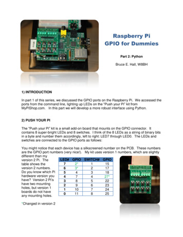
Raspberry PiGPIO for DummiesPart 2: PythonBruce E. Hall, W8BH1) INTRODUCTIONIn part 1 of this series, we discussed the GPIO ports on the Raspberry Pi. We accessed theports from the command line, lighting up LEDs on the “Push your Pi” kit fromMyPiShop.com. In this part we will develop a more robust interface using Python.2) PUSH YOUR PIThe “Push your Pi” kit is a small add-on board that mounts on the GPIO connector. Itcontains 8 super-bright LEDs and 8 switches. I think of the 8 LEDs as a string of binary bitsin a byte and number them accordingly, left to right: LED7 through LED0. The LEDs andswitches are connected to the GPIO ports as follows:You might notice that each device has a silkscreened number on the PCB. These numbersare the GPIO port numbers (very nice!). My kit uses version 1 numbers, which are slightlydifferent than myLED# GPIO SWITCH# GPIOversion 2 Pi. The72*115table shows theversion 2 numbers.63*217Do you know which Pi54318hardware version you47427*have? Version 2 Pi’s38522have two mounting29623holes, but version 1110724boards do not have011825any mounting holes.*Changed in version 2
3) PYTHONWhy Python? Other languages, like C, will work equally well. But Python seems to be apreferred language on the Raspberry Pi and this project a good excuse tolearn something about it. I prefer starting simple, getting small stuff to work, thenadding to it. If you like this method too then read on.There are two popular Python modules for GPIO programming: RPi.GPIO and WiringPi. Idownloaded and installed both. WiringPi is currently the most feature-complete, and alsohas a familiar feel to anyone used to Arduino coding. But I am going to skip over it, andwrite about RPi.GPIO instead. Try both and see which one you prefer.If you are using a recent version of Raspian on your Pi, then you already have RPi.GPIOinstalled. If not, visit the project home page at http://code.google.com/p/raspberrygpiopython/ to get the latest version.Let’s start with the interactive-mode python interpreter. RPi.GPIO must run from root, soplease login as root and start python. You will see the triple-chevron ( ) prompt: sudo su# python Import the RPi.GPIO module. The first thing we’ll do is configure it to use the Broadcomport-numbering scheme. And we’ll turn off warnings about port usage: import RPi.GPIO as GPIO GPIO.setmode(GPIO.BCM) GPIO.setwarnings(False)If python complains at the first statement, make sure that: 1) you have already installedRPi.GPIO; 2) you spelled it correctly, with a lower-case ‘i’; and 3) you started python fromroot.Now we are ready to specify which I/O pins we are going to use, and how we are going touse them. Let’s try GPIO4, like in part 1, which is attached to the third LED.We must declare it as an output. GPIO.setup (4, GPIO.OUT)Assuming that you got no feedback from the four python statements above, output onGPIO4 is ready. Let’s try lighting the LED GPIO.output(4,1)Is the LED on?. Use the output function again to turn it off: GPIO.output(4,0)
If your LED turned on & off, everything is working fine. Type exit() to leave python. It’s timeto write a real program.4) A SIMPLE PYTHON SCRIPTLet’s put these statements in the form of a python script. You can use IDLE, Geany, oreven a simple text editor like Nano to enter your code. The first line in your script should bea command that points to the proper interpreter of your code. In this case, we need to pointto the python interpreter, which is located at /usr/bin/python. We point to python using aninterpreter directive, the special character combination known as the shebang (#!).#!/usr/bin/pythonWe need to import the time module, in addition to RPi.GPIO. Now we have enough tocreate an honest-to-goodness python script. Copy the following into your editor of choice,and save it as blink.py:#!/usr/bin/pythonimport RPi.GPIO as GPIOimport ile True:GPIO.output(4, 1)time.sleep(1)GPIO.output(4, 0)time.sleep(1)Change the file permissions, and you can run it from the shell: sudo su# chmod x blink.py# ./blink.pyIf all goes well, the third LED (on GPIO4) should be blinking away. Hit Ctrl-C to stop thefun. We have the same result as we had in part1, but programmed from python instead ofbash. It is time to expand our code, and tackle multiple inputs & outputs.5) A BIGGER PYTHON SCRIPTFirst, for convenience & readability, declare each LED and switch in terms of its GPIO portnumber.LED7LED6 2 3#GPIO2; use 0 on rev1 boards#GPIO3; use 1 on rev1 boards
LED5LED4LED3LED2LED1LED0LEDS 0,LED1,LED2,LED3,LED4,LED5,LED6,LED7]SW1 15#GPIO15SW2 17#GPIO17SW3 18#GPIO18SW4 27#GPIO27; use 21 on rev1 boardsSW5 22#GPIO22SW6 23#GPIO23SW7 24#GPIO24SW8 25#GPIO25SWITCHES [SW1,SW2,SW3,SW4,SW5,SW6,SW7,SW8]Combine all of the I/O setup commands into a function called InitIO. We can set all of theLEDs as outputs using a for loop and the LED list. Similarly, we can set all of the switchesas inputs. We add an extra parameter to the input setup, enabling pull-up resistors. Theseinternal pull-ups keep the input at logic ‘1’ until the switch is pressed. Without the pull-upsenabled, the port input is ‘floating’ and at an unpredictable logic state.def lse)for led in LEDS:GPIO.setup(led,GPIO.OUT)for switch in SWITCHES:GPIO.setup(switch,GPIO.IN, pull up down GPIO.PUD UP)Next, create some small, helper functions that encapsulate direct calls to GPIO. Thesesimple routines let us set individual LEDs and read individual switches. Notice the ‘not’operator in the GetSwitch routine. Our switches are pulling the input port down to logic 0,and will result in a 0 result when the switch is pressed. The ‘not’ converts the 0 to 1, andvice versa. Also, the last four functions could be rewritten in terms of SetLed, if desired.You choose!def GetSwitch(index):#returns value of selected switch. Expects value 0-7return not GPIO.input(SWITCHES[index])def SetLed(num,value):#sets the led to desired value (1 on,0 off)GPIO.output(LEDS[num],value)def AllLedsOn():for led in LEDS:GPIO.output(led, GPIO.HIGH)def AllLedsOff():for led in LEDS:GPIO.output(led, GPIO.LOW)
def TurnOnLed(num):#turn on the indicated led. Expects num 0-7GPIO.output(LEDS[num], GPIO.HIGH)def TurnOffLed(num):#turn off the indicated led. Expects num 0-7GPIO.output(LEDS[num], GPIO.LOW)You should try them as you go. Start your main program block with InitIO(), then callwhichever of them you want to try. For instance, what would the following do?InitIO()AllLedsOn()time.delay(2)AllLedsOff()I like to build simple functions first and then call them, testing as I go. This ‘bottom-up’programming style works well for me, especially when I am learning how to do somethingnew. It is a good confidence-builder. Try some of your own simple functions. Perhaps youcan take the test code above and put it into its own ‘FlashLed’ function.Here is a more complex function: DisplayBinary. I want to be able to use the 8 LEDs todisplay an 8 bit binary number. For example, the number 101 in decimal is 0x65 inhexadecimal or 01100101 in binary. We’ll use the 8 LEDs to display these 8 bits:Led70Led61Led51Led40Led30Led21Led10Led01Every other LED should be on. To display any binary pattern, we look at each bit: if it’s aone, then turn the led on; otherwise turn it off. We can use the left shift ‘ ’ operator toselect each bit. For 0x65, the value of bit2 (the third bit from the right) is 1. To isolate thisbit, we can use a ‘mask’ that is all zeros except for bit2. Then, went we logically AND thevalue with this mask, the result will be greater than zero if bit2 was 1, and zero if bit2 bit1000bit0100Value 0x65Mask 1 2Result Value & MaskUsing this mask & value approach, it is easy to turn on the correct LEDs. Select each bit,and set the LED according to the result. Any nonzero result from (value & mask) will resultin the LED turning on.def DisplayBinary(value):#displays value on LEDS in binary formatfor bit in range(8):mask 1 bitSetLed(bit,value & mask)
Nice and neat. We can use the left shift operator for another trick: bar graphs. If we want tolight up any number of sequential LEDs, the corresponding binary value is (2 n) -1. Forinstance, 4 LEDs would be a value of 2 4 -1 16-1 15 (binary 00001111). Performing the2 n is just the left shift operator: 2 n (1 n). If you don’t believe me, type python on thecommand line to get into immediate-mode, then type ‘1 4’. You’ll get 16 (2 4) as youranswer. python 1 416 exit() Let’s see why that works. Start with 1 (binary 00000001) and shift it to the left. Every timeyou do, the value of the byte 010bit200100bit101000bit010000Starting value 1 (2 0)1st shift: value 2 (2 1)2nd shift: value 4 (2 2)3rd shift: value 8 (2 3)4th shift: value 16 (2 4)A bar graph function might come in handy, so let’s make one:def BarGraph (value):#light up same # of LEDs as value.temp 1 valueDisplayBinary(temp-1)Expects values 0-8That’s all for part 2. The script that follows includes a few additional display routines. Thereis also a routine for getting switch input. Try them out, and then add your own!
6) PYTHON SCRIPT for GPIO, PART ###########################################GPIO2 : Python control of the Raspberry Pi GPIO ports##Author : Bruce E. Hall bhall66@gmail.com #Date: 25 Mar 2013##Use this script with the “Push your Pi” kit from MyPiShop.com#See w8bh.net for more ###################################import RPi.GPIO as GPIOimport timeLED7LED6LED5LED4LED3LED2LED1LED0LEDS 2#GPIO2; use 0 on rev1 boards3#GPIO3; use 1 on rev1 11[LED0,LED1,LED2,LED3,LED4,LED5,LED6,LED7]SW1 15#GPIO15SW2 17#GPIO17SW3 18#GPIO18SW4 27#GPIO27; use 21 on rev1 boardsSW5 22#GPIO22SW6 23#GPIO23SW7 24#GPIO24SW8 25#GPIO25SWITCHES #######Bit-manipulation routines#Nothing here relates to GPIO or the 'Push your Pi' kit.#def ReverseBits (byte):#reverse the bit order in the byte: bit0 - bit 7, bit1 - bit6, etc.value 0currentBit 7for i in range(0,8):if byte & (1 i):value (0x80 i)currentBit - 1return valuedef ROR (byte):#perform a 'rotate right' command on byte#bit 1 is rotated into bit 7; everything else shifted rightbit1 byte & 0x01#get right-most bitbyte 1#shift right 1 bitif bit1:#was right-most bit a 1?byte 0x80#if so, rotate it into bit 7
return bytedef ROL (byte):#perform a 'rotate left' command on byte#bit 7 is rotated into bit 1; everything else shifted leftbit7 byte & 0x080#get bit7byte 1#shift left 1 bitbyte & 0xFF#only keep 8 bitsif bit7:#was bit7 a 1?byte 0x01#if so, rotate it into bit 1return ############################Low-level routines#These routines access GPIO directly#def lse)for led in LEDS:GPIO.setup(led,GPIO.OUT)for switch in SWITCHES:GPIO.setup(switch,GPIO.IN, pull up down GPIO.PUD UP)def GetSwitch(index):#returns value of selected switch. Expects value 0-7return not GPIO.input(SWITCHES[index])def SetLed(num,value):#sets the led to desired value (1 on,0 ######Intermediate-level routines#These routines perform simple tasks with the I/O devices,#def TurnOnLed(num):#turn on the indicated led.SetLed(num,1)def TurnOffLed(num):#turn off the indicated led.SetLed(num,0)Expects num 0-7Expects num 0-7def FlashLED(num, delay 0.08):#turn on specified LED for given amount of def AllLedsOn():for i in range(8):TurnOnLed(i)def AllLedsOff():for i in range(8):TurnOffLed(i)
def DisplayBinary(value):#displays value on LEDS in binary formatfor bit in range(8):mask 1 bitSetLed(bit,value & mask)def BarGraph (value):#light up same # of LEDs as value.temp 1 valueDisplayBinary(temp-1)Expects values ###########################Test routines:#These routines perform more complex tasks with the I/O devices,#calling on the low and intermediate level routinesdef BlinkAll(numCycles 4, delay 0.5):for count in dsOff()time.sleep(delay)def Count(upTo 0xFF, delay 0.1):#count in binary to the value 'upTo'for count in ef Cylon (numCycles 8, delay 0.08):#creates a cyclon animation on the LEDsfor count in range(numCycles):for i in range(7):FlashLED(i,delay)for i in range(7,0,-1):FlashLED(i,delay)def SwitchTest():#lights up LED associated with pressed switchprint "Press some switches. This test lasts about 15 seconds."for count in range(150):for i in range(8):SetLed(i,GetSwitch(i))time.sleep(0.1)def BarGraphTest(delay 0.4):#display 0 through 8 as a bar of lighted LEDsfor value in range(9):#count upBarGraph(value)time.sleep(delay)for value in range(7,-1,-1):#count back downBarGraph(value)time.sleep(delay)def RotateTest (numCycles 32, delay 0.05):#rotates a binary pattern on the LEDsfor i in range(1,8):pattern (1 i) - 1for count in range(numCycles):DisplayBinary(pattern)
time.sleep(delay)pattern ROR(pattern)for i in range(7,0,-1):pattern (1 i) - 1for count in delay)pattern ####################################Main #######
GPIO for Dummies Part 2: Python Bruce E. Hall, W8BH 1) INTRODUCTION In part 1 of this series, we discussed the GPIO ports on the Raspberry Pi. We accessed the ports from the command line, ligh