Transcription
Motor ns andcommissioningFirmware-Versionfrom 1.4.0.x.680401071404NH[8034520]
CMMS-AS/CMMS-ST/CMMD-ASTranslation of the original instructionsGDCP-CMMS/D-FW-ENCAN , CANopen , CiA , CODESYS , DeviceNet , EnDat , PROFIBUS , Windows are registeredtrademarks of the respective trademark owners in certain countries.Identification of hazards and instructions on how to prevent them:WarningHazards that can cause death or serious injuries.CautionHazards that can cause minor injuries or serious material damage.Other symbols:NoteMaterial damage or loss of function.Recommendations, tips, references to other documentation.Essential or useful accessories.Information on environmentally sound usage.Text designations: Activities that may be carried out in any order.1. Activities that should be carried out in the order stated.– General lists.2Festo – GDCP-CMMS/D-FW-EN – 1404NH –
CMMS-AS/CMMS-ST/CMMD-ASTable of contents – CMMS-AS/CMMS-ST/CMMD-AS1Safety and requirements for product use . . . . . . . . . . . . . . . . . . . . . . . . . . . . . . . . . . . . . .131.1Safety . . . . . . . . . . . . . . . . . . . . . . . . . . . . . . . . . . . . . . . . . . . . . . . . . . . . . . . . . . . . . . . . . .1.1.1Safety instructions . . . . . . . . . . . . . . . . . . . . . . . . . . . . . . . . . . . . . . . . . . . . . . . .1.1.2Intended use . . . . . . . . . . . . . . . . . . . . . . . . . . . . . . . . . . . . . . . . . . . . . . . . . . . . .Requirements for product use . . . . . . . . . . . . . . . . . . . . . . . . . . . . . . . . . . . . . . . . . . . . . . .1.2.1Transport and storage conditions . . . . . . . . . . . . . . . . . . . . . . . . . . . . . . . . . . . .1.2.2Technical requirements . . . . . . . . . . . . . . . . . . . . . . . . . . . . . . . . . . . . . . . . . . . .1.2.3Qualification of trained personnel . . . . . . . . . . . . . . . . . . . . . . . . . . . . . . . . . . . .1.2.4Range of application and certifications . . . . . . . . . . . . . . . . . . . . . . . . . . . . . . . .13131415151515162Product overview . . . . . . . . . . . . . . . . . . . . . . . . . . . . . . . . . . . . . . . . . . . . . . . . . . . . . . . . .172.1Motor controller CMMS-AS-C4-3A-G2 . . . . . . . . . . . . . . . . . . . . . . . . . . . . . . . . . . . . . . . . .2.1.1Control, sensor and safety function interfaces . . . . . . . . . . . . . . . . . . . . . . . . . .2.1.2Power supply, motor and motor encoder interfaces . . . . . . . . . . . . . . . . . . . . . .2.1.3Parameter/firmware interfaces . . . . . . . . . . . . . . . . . . . . . . . . . . . . . . . . . . . . . .2.1.4LED indicators, seven-segment displays and DIL switches . . . . . . . . . . . . . . . . .Motor controller CMMS-ST-C8-7-G2 . . . . . . . . . . . . . . . . . . . . . . . . . . . . . . . . . . . . . . . . . . .2.2.1Control, sensor and safety function interfaces . . . . . . . . . . . . . . . . . . . . . . . . . .2.2.2Power supply, motor and motor encoder interfaces . . . . . . . . . . . . . . . . . . . . . .2.2.3Parameter/firmware interfaces . . . . . . . . . . . . . . . . . . . . . . . . . . . . . . . . . . . . . .2.2.4LED indicators, seven-segment displays and DIL switches . . . . . . . . . . . . . . . . .Motor controller CMMD-AS-C8-3A . . . . . . . . . . . . . . . . . . . . . . . . . . . . . . . . . . . . . . . . . . . .2.3.1Control, sensor and safety function interfaces . . . . . . . . . . . . . . . . . . . . . . . . . .2.3.2Power supply, motor and motor encoder interfaces . . . . . . . . . . . . . . . . . . . . . .2.3.3Parameter/firmware interfaces . . . . . . . . . . . . . . . . . . . . . . . . . . . . . . . . . . . . . .2.3.4LED indicators, seven-segment displays and DIL switches . . . . . . . . . . . . . . . . .Control interfaces – operating modes – operational functions . . . . . . . . . . . . . . . . . . . . . .2.4.1Overview: Control interfaces/connections/device profiles/operating modes/operational functions . . . . . . . . . . . . . . . . . . . . . . . . . . . . . . .2.4.2Positioning mode: Direct mode, individual record mode,record linking mode and interpolated positioning mode . . . . . . . . . . . . . . . . . . .2.4.3Positioning mode: Homing mode/jog mode/teach mode . . . . . . . . . . . . . . . . . .2.4.4Speed mode, force mode and torque mode . . . . . . . . . . . . . . . . . . . . . . . . . . . .2.4.5Synchronisation . . . . . . . . . . . . . . . . . . . . . . . . . . . . . . . . . . . . . . . . . . . . . . . . . .2.4.6Operational functions: Encoder emulation, flying measurement,analogue monitor and endless positioning . . . . . . . . . . . . . . . . . . . . . . . . . . . . .171719212325252729313333353739411.22.22.32.4Festo – GDCP-CMMS/D-FW-EN – 1404NH – English4142434445463
CMMS-AS/CMMS-ST/CMMD-AS3Control interfaces . . . . . . . . . . . . . . . . . . . . . . . . . . . . . . . . . . . . . . . . . . . . . . . . . . . . . . . . .473.1Digital, analogue, synchronisation and fieldbus interfaces . . . . . . . . . . . . . . . . . . . . . . . . .3.1.1Motor controller CMMS-AS-C4-3A-G2 . . . . . . . . . . . . . . . . . . . . . . . . . . . . . . . . .3.1.2Motor controller CMMS-ST-C8-7-G2 . . . . . . . . . . . . . . . . . . . . . . . . . . . . . . . . . .3.1.3Motor controller CMMD-AS-C8-3A . . . . . . . . . . . . . . . . . . . . . . . . . . . . . . . . . . . .Digital interfaces [X1] [X1.1/X1.2/EXT1/EXT2] . . . . . . . . . . . . . . . . . . . . . . . . . . . . . . . . . .3.2.1Digital I/O modules (DIN /DOUT ) . . . . . . . . . . . . . . . . . . . . . . . . . . . . . . . . . .3.2.2Selecting the operating mode/mode via digital input signals . . . . . . . . . . . . . . .3.2.3Digital input/output signals as a function of the operating mode/mode . . . . . .3.2.4Digital input signals . . . . . . . . . . . . . . . . . . . . . . . . . . . . . . . . . . . . . . . . . . . . . . .3.2.5Digital output signals . . . . . . . . . . . . . . . . . . . . . . . . . . . . . . . . . . . . . . . . . . . . . .3.2.6Message “Target reached” . . . . . . . . . . . . . . . . . . . . . . . . . . . . . . . . . . . . . . . . . .3.2.7Message “Following error” . . . . . . . . . . . . . . . . . . . . . . . . . . . . . . . . . . . . . . . . . .3.2.8Message “Speed reached” . . . . . . . . . . . . . . . . . . . . . . . . . . . . . . . . . . . . . . . . .3.2.9Message “Remaining distance” . . . . . . . . . . . . . . . . . . . . . . . . . . . . . . . . . . . . . .Analogue interface [X1] [X1.1/X1.2] . . . . . . . . . . . . . . . . . . . . . . . . . . . . . . . . . . . . . . . . . . .3.3.1Analogue input/output (AIN0/AMON0) . . . . . . . . . . . . . . . . . . . . . . . . . . . . . . . .3.3.2Analogue input signal (analogue setpoint value specification) . . . . . . . . . . . . . .3.3.3Analogue output signal (analogue monitor) . . . . . . . . . . . . . . . . . . . . . . . . . . . .Synchronisation interfaces [X1/X10] [X1.1/X1.2/X10.1/X10.2] . . . . . . . . . . . . . . . . . . . . .3.4.1Encoder input for synchronisation (slave interface) . . . . . . . . . . . . . . . . . . . . . .3.4.2Encoder output for encoder emulation (master interface) . . . . . . . . . . . . . . . . .3.4.3Incremental signals (A/#A/B/#B/N/#N) . . . . . . . . . . . . . . . . . . . . . . . . . . . . . . .3.4.4Pulse/direction signals (CLK/#CLK/DIR/#DIR) . . . . . . . . . . . . . . . . . . . . . . . . . .3.4.5Forward/reverse signals (CW/#CW/CCW/#CCW) . . . . . . . . . . . . . . . . . . . . . . . .Fieldbus interfaces [X4] [X5] [EXT/EXT1] . . . . . . . . . . . . . . . . . . . . . . . . . . . . . . . . . . . . . . .3.5.1Supported fieldbuses . . . . . . . . . . . . . . . . . . . . . . . . . . . . . . . . . . . . . . . . . . . . . .3.5.2Required digital inputs/outputs with a fieldbus activation . . . . . . . . . . . . . . . . .Device profiles for fieldbuses . . . . . . . . . . . . . . . . . . . . . . . . . . . . . . . . . . . . . . . . . . . . . . . .3.6.1Device profile: Festo handling and positioning profile (FHPP) . . . . . . . . . . . . . .3.6.2Device profile: CANopen, CiA 402 (for electric drives) . . . . . . . . . . . . . . . . . . . 373747575754Measuring system . . . . . . . . . . . . . . . . . . . . . . . . . . . . . . . . . . . . . . . . . . . . . . . . . . . . . . . .764.1Measuring system for electrical drives . . . . . . . . . . . . . . . . . . . . . . . . . . . . . . . . . . . . . . . . .4.1.1Measuring system for linear drives . . . . . . . . . . . . . . . . . . . . . . . . . . . . . . . . . . .4.1.2Measuring system for rotative drives . . . . . . . . . . . . . . . . . . . . . . . . . . . . . . . . . .Calculation rules for the measuring system . . . . . . . . . . . . . . . . . . . . . . . . . . . . . . . . . . . . .Limit switch (hardware) and software end position . . . . . . . . . . . . . . . . . . . . . . . . . . . . . . .4.3.1Limit switch LSN/LSP (hardware) . . . . . . . . . . . . . . . . . . . . . . . . . . . . . . . . . . . .4.3.2Software end position SLN/SLP . . . . . . . . . . . . . . . . . . . . . . . . . . . . . . . . . . . . . .767677787878783.23.33.43.53.64.24.34Festo – GDCP-CMMS/D-FW-EN – 1404NH – English
CMMS-AS/CMMS-ST/CMMD-AS5Commissioning . . . . . . . . . . . . . . . . . . . . . . . . . . . . . . . . . . . . . . . . . . . . . . . . . . . . . . . . . . .795.1Configuration/parameterisation of the drive system and motor controller . . . . . . . . . . . . .5.1.1Festo Configuration Tool (FCT) . . . . . . . . . . . . . . . . . . . . . . . . . . . . . . . . . . . . . . .5.1.2Installing the FCT framework/plug-in . . . . . . . . . . . . . . . . . . . . . . . . . . . . . . . . . .5.1.3Configuring/parameterising the Festo Configuration Tool (FCT) . . . . . . . . . . . . .5.1.4FCT Help . . . . . . . . . . . . . . . . . . . . . . . . . . . . . . . . . . . . . . . . . . . . . . . . . . . . . . . .5.1.5Configuring fieldbus/firmware functions via DIL switch . . . . . . . . . . . . . . . . . . .5.1.6Fieldbus address/MAC-ID configuration . . . . . . . . . . . . . . . . . . . . . . . . . . . . . . .5.1.7Firmware download activation from the memory card . . . . . . . . . . . . . . . . . . . .5.1.8Data rate configuration (CAN bus/DeviceNet) . . . . . . . . . . . . . . . . . . . . . . . . . .5.1.9CAN bus activation . . . . . . . . . . . . . . . . . . . . . . . . . . . . . . . . . . . . . . . . . . . . . . . .5.1.10Terminating resistor activation (CAN bus) . . . . . . . . . . . . . . . . . . . . . . . . . . . . . .Data interfaces (parameter/firmware) . . . . . . . . . . . . . . . . . . . . . . . . . . . . . . . . . . . . . . . . .5.2.1Firmware file . . . . . . . . . . . . . . . . . . . . . . . . . . . . . . . . . . . . . . . . . . . . . . . . . . . . .5.2.2Downloading the firmware file (FCT motor controller) . . . . . . . . . . . . . . . . . . .5.2.3Downloading the firmware file (.S) (memory card motor controller) . . . . . . . .5.2.4Device data (FCT) . . . . . . . . . . . . . . . . . . . . . . . . . . . . . . . . . . . . . . . . . . . . . . . . .5.2.5Downloading/synchronising/uploading/saving device data(FCT / / motor controller) . . . . . . . . . . . . . . . . . . . . . . . . . . . . . . . . . . . . . .5.2.6Archiving/extracting device data (FCT / PC) . . . . . . . . . . . . . . . . . . . . . . . . . .5.2.7Parameter file (.DCO) . . . . . . . . . . . . . . . . . . . . . . . . . . . . . . . . . . . . . . . . . . . . . .5.2.8Reading/writing/saving the parameter file (.DCO)(memory card / motor controller) . . . . . . . . . . . . . . . . . . . . . . . . . . . . . . . . . .Commissioning the motor controller . . . . . . . . . . . . . . . . . . . . . . . . . . . . . . . . . . . . . . . . . .5.3.1Preparing for initial start-up . . . . . . . . . . . . . . . . . . . . . . . . . . . . . . . . . . . . . . . . .5.3.2Required digital inputs/outputs for operation . . . . . . . . . . . . . . . . . . . . . . . . . .5.3.3Status diagram of the motor controller . . . . . . . . . . . . . . . . . . . . . . . . . . . . . . . .5.3.4Switching on the power supply (Power ON) . . . . . . . . . . . . . . . . . . . . . . . . . . . .5.3.5Downloading device data (FCT) to the motor controller . . . . . . . . . . . . . . . . . . .5.3.6Enabling the motor controller via digital inputs . . . . . . . . . . . . . . . . . . . . . . . . . .5.3.7Commutation finding by motor controller CMMS-ST-C8-7-G2 . . . . . . . . . . . . . . .5.3.8Checking motor and limit switch functionality . . . . . . . . . . . . . . . . . . . . . . . . . . .5.3.9Carrying out homing . . . . . . . . . . . . . . . . . . . . . . . . . . . . . . . . . . . . . . . . . . . . . . .Behaviour of the motor controller in the event of an interruption or disconnection . . . . . .5.4.1Holding brake . . . . . . . . . . . . . . . . . . . . . . . . . . . . . . . . . . . . . . . . . . . . . . . . . . . .5.4.2Interruption of the mains supply . . . . . . . . . . . . . . . . . . . . . . . . . . . . . . . . . . . . .5.4.3Switching off the motor controller via output stage enable (DIN4) . . . . . . . . . .5.4.4Switching off the motor controller via controller enable (DIN5) . . . . . . . . . . . . .Master control . . . . . . . . . . . . . . . . . . . . . . . . . . . . . . . . . . . . . . . . . . . . . . . . . . . . . . . . . . . .5.5.1Master control over the motor controller . . . . . . . . . . . . . . . . . . . . . . . . . . . . . . .5.5.2FCT master control over the motor controller . . . . . . . . . . . . . . . . . . . . . . . . . . .797980808182838484848586878788905.25.35.45.5Festo – GDCP-CMMS/D-FW-EN – 1404NH – 081091101101125
CMMS-AS/CMMS-ST/CMMD-AS6Positioning mode . . . . . . . . . . . . . . . . . . . . . . . . . . . . . . . . . . . . . . . . . . . . . . . . . . . . . . . . .113Function: Position control . . . . . . . . . . . . . . . . . . . . . . . . . . . . . . . . . . . . . . . . . . . . . . . . . . .Record selection and positioning records . . . . . . . . . . . . . . . . . . . . . . . . . . . . . . . . . . . . . .6.2.1Function: Record selection and positioning records . . . . . . . . . . . . . . . . . . . . . .6.2.2Record selection (positioning record) – control interface – operating mode . . .6.3 Relative positioning . . . . . . . . . . . . . . . . . . . . . . . . . . . . . . . . . . . . . . . . . . . . . . . . . . . . . . .6.4 Direct mode . . . . . . . . . . . . . . . . . . . . . . . . . . . . . . . . . . . . . . . . . . . . . . . . . . . . . . . . . . . . . .6.4.1Function: Direct mode . . . . . . . . . . . . . . . . . . . . . . . . . . . . . . . . . . . . . . . . . . . . .6.4.2Connection: Digital inputs/outputs . . . . . . . . . . . . . . . . . . . . . . . . . . . . . . . . . . .6.4.3Parameterising the direct mode . . . . . . . . . . . . . . . . . . . . . . . . . . . . . . . . . . . . . .6.5 Individual record mode . . . . . . . . . . . . . . . . . . . . . . . . . . . . . . . . . . . . . . . . . . . . . . . . . . . . .6.5.1Function: Individual record mode . . . . . . . . . . . . . . . . . . . . . . . . . . . . . . . . . . . .6.5.2Connection: Digital inputs/outputs . . . . . . . . . . . . . . . . . . . . . . . . . . . . . . . . . . .6.5.3Timing diagram: Start/cancel individual record . . . . . . . . . . . . . . . . . . . . . . . . .6.5.4Parameterising the individual record mode . . . . . . . . . . . . . . . . . . . . . . . . . . . . .6.6 Record linking mode . . . . . . . . . . . . . . . . . . . . . . . . . . . . . . . . . . . . . . . . . . . . . . . . . . . . . . .6.6.1Function: Record linking mode . . . . . . . . . . . . . . . . . . . . . . . . . . . . . . . . . . . . . . .6.6.2Connection: Digital inputs/outputs . . . . . . . . . . . . . . . . . . . . . . . . . . . . . . . . . . .6.6.3Timing diagram: Start/interrupt/cancel record sequence . . . . . . . . . . . . . . . . .6.6.4Parameterising the record linking mode . . . . . . . . . . . . . . . . . . . . . . . . . . . . . . .6.7 Interpolated positioning mode . . . . . . . . . . . . . . . . . . . . . . . . . . . . . . . . . . . . . . . . . . . . . . .6.7.1Function: Interpolated positioning mode . . . . . . . . . . . . . . . . . . . . . . . . . . . . . .6.7.2Connection: Digital inputs/outputs . . . . . . . . . . . . . . . . . . . . . . . . . . . . . . . . . . .6.8 Homing mode/homing . . . . . . . . . . . . . . . . . . . . . . . . . . . . . . . . . . . . . . . . . . . . . . . . . . . . .6.8.1Function: Homing mode . . . . . . . . . . . . . . . . . . . . . . . . . . . . . . . . . . . . . . . . . . . .6.8.2Connection: Digital inputs/outputs . . . . . . . . . . . . . . . . . . . . . . . . . . . . . . . . . . .6.8.3Timing diagram: Cancelling homing to limit switch/stop . . . . . . . . . . . . . . . . . .6.8.4Configuring and parameterising the homing mode/homing . . . . . . . . . . . . . . . .6.9 Jog mode . . . . . . . . . . . . . . . . . . . . . . . . . . . . . . . . . . . . . . . . . . . . . . . . . . . . . . . . . . . . . . . .6.9.1Function: Jog mode . . . . . . . . . . . . . . . . . . . . . . . . . . . . . . . . . . . . . . . . . . . . . . . .6.9.2Jog mode via Festo Configuration Tool (FCT) . . . . . . . . . . . . . . . . . . . . . . . . . . . .6.9.3Connection: Digital inputs/outputs . . . . . . . . . . . . . . . . . . . . . . . . . . . . . . . . . . .6.9.4Timing diagram: Jog travel via jog /jog– . . . . . . . . . . . . . . . . . . . . . . . . . . . . . . .6.9.5Parameterise jog mode . . . . . . . . . . . . . . . . . . . . . . . . . . . . . . . . . . . . . . . . . . . .6.10 Teach mode . . . . . . . . . . . . . . . . . . . . . . . . . . . . . . . . . . . . . . . . . . . . . . . . . . . . . . . . . . . . . .6.10.1Function: Teach mode . . . . . . . . . . . . . . . . . . . . . . . . . . . . . . . . . . . . . . . . . . . . .6.10.2Connection: Digital inputs/outputs . . . . . . . . . . . . . . . . . . . . . . . . . . . . . . . . . . .6.10.3Timing diagram: Teaching the current actual position of the drive . . . . . . . . . . .6.10.4Parameterising the teach mode . . . . . . . . . . . . . . . . . . . . . . . . . . . . . . . . . . . . . 1781781791811826.16.26Festo – GDCP-CMMS/D-FW-EN – 1404NH – English
CMMS-AS/CMMS-ST/CMMD-AS7Speed mode and force/torque mode . . . . . . . . . . . . . . . . . . . . . . . . . . . . . . . . . . . . . . . . . .1837.1Speed mode . . . . . . . . . . . . . . . . . . . . . . . . . . . . . . . . . . . . . . . . . . . . . . . . . . . . . . . . . . . . .7.1.1Function: Speed adjustment . . . . . . . . . . . . . . . . . . . . . . . . . . . . . . . . . . . . . . . .7.1.2Function: Speed mode . . . . . . . . . . . . . . . . . . . . . . . . . . . . . . . . . . . . . . . . . . . . .7.1.3Connection: Analogue and digital inputs/outputs . . . . . . . . . . . . . . . . . . . . . . .7.1.4Parameterise speed mode . . . . . . . . . . . . . . . . . . . . . . . . . . . . . . . . . . . . . . . . . .Force/torque mode . . . . . . . . . . . . . . . . . . . . . . . . . . . . . . . . . . . . . . . . . . . . . . . . . . . . . . . .7.2.1Function: Current regulation . . . . . . . . . . . . . . . . . . . . . . . . . . . . . . . . . . . . . . . .7.2.2Function: Force/torque mode . . . . . . . . . . . . . . . . . . . . . . . . . . . . . . . . . . . . . . .7.2.3Connection: Analogue and digital I/O modules . . . . . . . . . . . . . . . . . . . . . . . . . .7.2.4Parameterise force/torque mode . . . . . . . . . . . . . . . . . . . . . . . . . . . . . . . . . . . .1831831841851861881881891901918Synchronisation . . . . . . . . . . . . . . . . . . . . . . . . . . . . . . . . . . . . . . . . . . . . . . . . . . . . . . . . . .1938.1Synchronisation (slave mode) . . . . . . . . . . . . . . . . . . . . . . . . . . . . . . . . . . . . . . . . . . . . . . .8.1.1Function: Synchronisation . . . . . . . . . . . . . . . . . . . . . . . . . . . . . . . . . . . . . . . . . .8.1.2Connection: Digital inputs/outputs (24 V) and encoder input (5 V) . . . . . . . . . .8.1.3Connection: Digital inputs/outputs (24 V) . . . . . . . . . . . . . . . . . . . . . . . . . . . . . .8.1.4Timing diagram: Starting synchronisation via Start Sync signal . . . . . . . . . . . . .8.1.5Configure/parameterise synchronisation . . . . . . . . . . . . . . . . . . . . . . . . . . . . . .1931931951961971989Operational functions . . . . . . . . . . . . . . . . . . . . . . . . . . . . . . . . . . . . . . . . . . . . . . . . . . . . .1999.1Encoder emulation (master operation) . . . . . . . . . . . . . . . . . . . . . . . . . . . . . . . . . . . . . . . .9.1.1Function: Encoder emulation . . . . . . . . . . . . . . . . . . . . . . . . . . . . . . . . . . . . . . . .9.1.2Connection: Encoder output (5 V) . . . . . . . . . . . . . . . . . . . . . . . . . . . . . . . . . . . .9.1.3Configure/parameterise encoder emulation . . . . . . . . . . . . . . . . . . . . . . . . . . . .Flying measurement (sampling) . . . . . . . . . . . . . . . . . . . . . . . . . . . . . . . . . . . . . . . . . . . . . .9.2.1Function: Flying measurement . . . . . . . . . . . . . . . . . . . . . . . . . . . . . . . . . . . . . . .9.2.2Connection: Digital input . . . . . . . . . . . . . . . . . . . . . . . . . . . . . . . . . . . . . . . . . . .Analogue monitor . . . . . . . . . . . . . . . . . . . . . . . . . . . . . . . . . . . . . . . . . . . . . . . . . . . . . . . . .9.3.1Function: Analogue monitor . . . . . . . . . . . . . . . . . . . . . . . . . . . . . . . . . . . . . . . . .9.3.2Connection: Analogue output . . . . . . . . . . . . . . . . . . . . . . . . . . . . . . . . . . . . . . .9.3.3Configure/parameterise analogue monitor . . . . . . . . . . . . . . . . . . . . . . . . . . . . .Endless positioning . . . . . . . . . . . . . . . . . . . . . . . . . . . . . . . . . . . . . . . . . . . . . . . . . . . . . . . .9.4.1Function: Endless positioning . . . . . . . . . . . . . . . . . . . . . . . . . . . . . . . . . . . . . . .Resonance filter (motor controller CMMS-ST-C8-7-G2) . . . . . . . . . . . . . . . . . . . . . . . . . . . .9.5.1Function: Resonance filter . . . . . . . . . . . . . . . . . . . . . . . . . . . . . . . . . . . . . . . . . .29.39.49.5Festo – GDCP-CMMS/D-FW-EN – 1404NH – English7
CMMS-AS/CMMS-ST/CMMD-AS10Service . . . . . . . . . . . . . . . . . . . . . . . . . . . . . . . . . . . . . . . . . . . . . . . . . . . . . . . . . . . . . . . . .20910.1 Protective and service functions . . . . . . . . . . . . . . . . . . . . . . . . . . . . . . . . . . . . . . . . . . . . . .10.1.1Overload current and short-circuit monitoring of the motor output . . . . . . . . . .10.1.2Monitoring of interruption and failure of the mains supply . . . . . . . . . . . . . . . . .10.1.3Overvoltage and undervoltage monitoring for the intermediate circuit . . . . . . .10.1.4Output stage temperature monitoring . . . . . . . . . . . . . . . . . . . . . . . . . . . . . . . . .10.1.5Monitoring the motor and motor encoder . . . . . . . . . . . . . . . . . . . . . . . . . . . . . .10.1.6I2t monitoring . . . . . . . . . . . . . . . . . . . . . . . . . . . . . . . . . . . . . . . . . . . . . . . . . . . .10.2 Operating mode and error messages . . . . . . . . . . . . . . . . . . . . . . . . . . . . . . . . . . . . . . . . . .10.2.1LED indicators (Ready/CAN/Bus) . . . . . . . . . . . . . . . . . . . . . . . . . . . . . . . . . . . .10.2.2Seven-segments display . . . . . . . . . . . . . . . . . . . . . . . . . . . . . . . . . . . . . . . . . . .10.3 Acknowledgement of error messages . . . . . . . . . . . . . . . . . . . . . . . . . . . . . . . . . . . . . . . . .10.3.1Diagnostic messages . . . . . . . . . . . . . . . . . . . . . . . . . . . . . . . . . . . . . . . . . . . . . .10.4 Dismantling and repairs . . . . . . . . . . . . . . . . . . . . . . . . . . . . . . . . . . . . . . . . . . . . . . . . . . . .10.4.1Saving the parameter set for the motor controller . . . . . . . . . . . . . . . . . . . . . . stic messages . . . . . . . . . . . . . . . . . . . . . . . . . . . . . . . . . . . . . . . . . . . . . . . . . . . . . .217A.1A.2A.3A.4Explanations on the diagnostic messages . . . . . . . . . . . . . . . . . . . . . . . . . . . . . . . . . . . . . .Diagnostic messages with instructions for fault clearance . . . . . . . . . . . . . . . . . . . . . . . . .Error codes via CiA 301/402 . . . . . . . . . . . . . . . . . . . . . . . . . . . . . . . . . . . . . . . . . . . . . . . . .Profibus diagnostics . . . . . . . . . . . . . . . . . . . . . . . . . . . . . . . . . . . . . . . . . . . . . . . . . . . . . . .217218231233BSerial interface RS232 (diagnostics/parameterisation interface) . . . . . . . . . . . . . . . . . .236B.1Activating the motor controller via the interface RS232 . . . . . . . . . . . . . . . . . . . . . . . . . . .B.1.1Master data of the interface RS232 . . . . . . . . . . . . . . . . . . . . . . . . . . . . . . . . . . .B.1.2Connect RS232 interface with a program . . . . . . . . . . . . . . . . . . . . . . . . . . . . . .B.1.3Connection [X5]: Pin allocation of the RS232 interface . . . . . . . . . . . . . . . . . . .Commands/syntax of the RS232 interface . . . . . . . . . . . . . . . . . . . . . . . . . . . . . . . . . . . . . .B.2.1General commands . . . . . . . . . . . . . . . . . . . . . . . . . . . . . . . . . . . . . . . . . . . . . . .B.2.2Control motor controller via CAN-Interpreter (CI) . . . . . . . . . . . . . . . . . . . . . . . .236236236237238238238CSerial interface RS485 (control interface) . . . . . . . . . . . . . . . . . . . . . . . . . . . . . . . . . . . . .241C.1Activating the motor controller via the interface RS485 . . . . . . . . . . . . . . . . . . . . . . . . . . .C.1.1Master data of the interface RS485 . . . . . . . . . . . . . . . . . . . . . . . . . . . . . . . . . . .C.1.2Connection [X5]: Pin allocation of the RS485 interface . . . . . . . . . . . . . . . . . . .Configure RS485 interface in the Festo Configuration Tool (FCT) . . . . . . . . . . . . . . . . . . . .Commands/syntax of the RS485 interface . . . . . . . . . . . . . . . . . . . . . . . . . . . . . . . . . . . . . .241241241242243B.2C.2C.38Festo – GDCP-CMMS/D-FW-EN – 1404NH – English
CMMS-AS/CMMS-ST/CMMD-ASInstructions on this descriptionThis documentation is intended to help you work safely with the motor controller CMMS-AS/CMMS-ST/CMMD-AS and describes the functions, commissioning procedure and error messages.Target groupThis documentation is intended exclusively for technicians trained in control and automation technology, who have experience in installation, commissioning, programming and diagnostics of positioningsystems.VersionsThis documentation refers to the following versions:Motor controllerVersionCMMS-AS-.Motor controller CMMS-AS-C4-3A-G2: From Rev 03Firmware: From version 1.4.0.2.6FCT plug-in CMMS-AS: From version 2.0.0.xMotor controller CMMS-ST-C8-7-G2: From Rev 05Firmware: From version 1.4.0.1.6FCT plug-in CMMS-ST: From version 2.0.0.xMotor controller CMMD-AS-C8-3A: From Rev 03Firmware: From version 1.4.0.3.6FCT plug-in CMMD-AS: From version 2.0.0.xCMMS-ST-.CMMD-AS-.NoteBefore using a newer firmware version, check whether a newer version of the FCT plugin or documentation is available Support portal: http://www.festo.com/sp.ServicePlease consult your regional Festo contact if you have any technical problems.Product identificationFor additional information about the rating plate and manufacturing date “Mounting and installation” description, GDCP-CMMS-AS-G2-HW- /GDCP-CMMD-AS-HW- /GDCP-CMMS-ST-G2-HW- Festo – GDCP-CMMS/D-FW-EN – 1404NH – English9
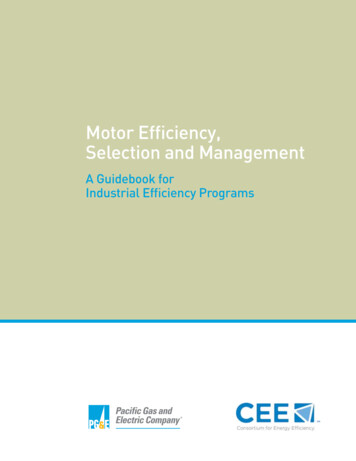
CMMS-AS/CMMS-ST/CMMD-ASType codes CMMS-AS-C4-3A-G2CMMS – AS– C4– 3A– G2CMMS – ST– C8– 7– G2InterfacesCMMSMotor controller, standardMotor technologyASAC synchronousNominal currentC44AInput voltage3A230 V ACGenerationG22nd generationFig. 1Type codes CMMS-AS-C4-3A-G2Type codes CMMS-ST-C8-7-G2InterfacesCMMSMotor controller, standardMotor technologySTStepper motorNominal currentC88AInput voltage748 V DCGenerationG22nd generationFig. 210Type codes CMMS-ST-C8-7-G2Festo – GDCP-CMMS/D-FW-EN – 1404NH – English
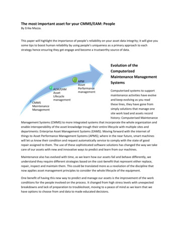
CMMS-AS/CMMS-ST/CMMD-ASType codes CMMD-AS-C8-3ACMMD – AS– C8– 3AInterfacesCMMDMotor controller, doubleMotor technologyASAC synchronousNominal currentC88AInput voltage3A230 V ACFig. 3Type codes CMMD-AS-C8-3AFesto – GDCP-CMMS/D-FW-EN – 1404NH – English11
CMMS-AS/CMMS-ST/CMMD-ASDocumentationAdditional information on the motor controllers CMMS-AS/CMMS-ST/CMMD-AS can be found in thefollowing documentation:DocumentationAssembly HW-.CMMS-ST––––MountingI t ll ti ((pinInstallationi allocations)llti)Error messagesTechnical dataFunctions and – Control interfaces– Operating modes/operationalfunctions– Commissioning with FCT– Error messagesSTO -ASCMMS-STCMMS-ASCMMD-ASCMMS-STDevice profileCiA 402GDCP-CMMS/D-C-CO-.CMMS-ASCMMD-ASCMMS-ST– Functional safetyy engineeringgg withthe STO safety function (SafeTorque Off )– Description of the interfaces:– CAN bus (CANopen)– Interface CAMC-PB (PROFIBUS)– Interface CAMC-DN (DeviceNet)– Control and parameterisation viathe device profile FHPP (FestoHandling and Positioning Profile)with PROFIBUS, DeviceNet orCANopen.– Description of the interface:– CAN bus (CANopen, DriveBus)– Control and parameterisation viathe device profile CiA 402 (DS402).Software HelpHelp for the CMMS-AS plug-in CMMS-ASHelp for the CMMD-AS plug-in CMMD-ASHelp for the CMMS-ST plug-in CMMS-STDeviceprofile FHPPTab. 1– User interface and functions in theFesto Configuration Tool for theplug-inDocumentation on the motor controllersThe documentation is available on the following media:– CD-ROM
Description Fuctionsand commissioning Firmware-Version from1.4.0.x.6 8040107 1404NH [8034520] Motor controller CMMS-AS/CMMS-ST/CMMD-AS