Transcription
MAKING MODERN LIVING POSSIBLEwww.danfoss.com/drivesInstructionVLTp HVAC Basic DriveCascade Controller130R0267MI18I302*MI18I302*Rev. 2012-08-30
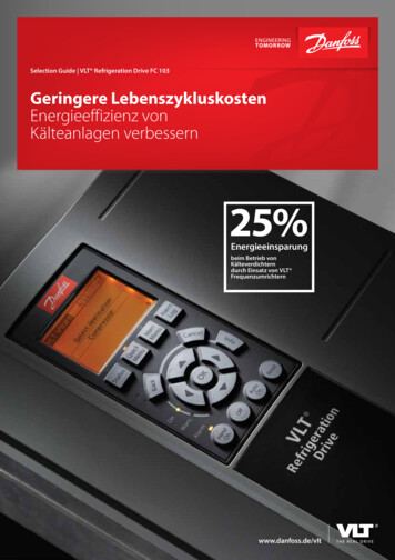
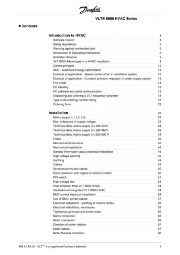
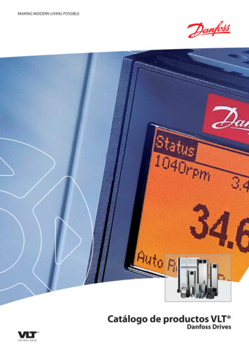
VLT HVAC Basic Drive Casca.VLT HVAC Basic Drive Cascade Controller1.1 Cascade ControllerVariable SpeedPumps (1)Motor starter130BA362.10Constant SpeedPumps (2)Pressure SensorFrequency ConverterwithCascade ControllerIllustration 1.1 Cascade ControllerThe Cascade Controller is used for pump applicationswhere a certain pressure (“head”) or level needs to bemaintained over a wide dynamic range. Running a largepump at variable speed over a wide for range is not anideal solution because of low pump efficiency and becausethere is a practical limit of about 25% rated full load speedfor running a pump.In the Cascade Controller the frequency converter controlsa variable speed motor as the variable speed pump (lead)and can stage up to two additional constant speed pumpson and off. By varying the speed of the initial pump,variable speed control of the entire system is provided.This maintains constant pressure while eliminatingpressure surges, resulting in reduced system stress andquieter operation in pumping systems.Fixed Lead PumpThe motors must be of equal size. The Cascade Controllerallows the frequency converter to control up to 5 equalsize pumps using the drives two built-in relays andterminal 27, 29 (digital input/digital output). When thevariable pump (lead) is connected directly to the frequencyconverter, the other 4 pumps are controlled by the twobuilt-in relays and terminal 27, 29 (digital input/digitaloutput). Lead pump alternation can not be chosen whenlead pump is fixed.The command can be a manual alternation or analternation event signal. If the alternation event is selected,the lead pump alternation takes place every time theevent occurs. Selections include whenever an alternationtimer expires, when the lead pump goes into sleep mode.Staging is determined by the actual system load.25-55 Alternate if Load 50% 1, if load 50% Alternationwill not happen. If load 50% Alternation will happen.When 25-55 Alternate if Load 50% 0, Alternation willhappen no matter with Load. Total pump capacity isdetermined as lead pump plus lag speed pumps capacities.Bandwidth ManagementIn cascade control systems, to avoid frequent switching offixed speed pumps, the desired system pressure is keptwithin a bandwidth rather than at a constant level. TheStaging Bandwidth provides the required bandwidth foroperation. When a large and quick change in systempressure occurs, the Override Bandwidth overrides theStaging Bandwidth to prevent immediate response to ashort duration pressure change. An Override BandwidthTimer can be programmed to prevent staging until thesystem pressure has stabilized and normal controlestablished.When the Cascade Controller is enabled and runningnormally and the frequency converter issues a trip alarm,the system head is maintained by staging and destagingfixed speed pumps. To prevent frequent staging anddestaging and minimize pressure fluxuations, a wider FixedSpeed Bandwidth is used instead of the Stagingbandwidth.Illustration 1.2 BandwidthLead Pump AlternationThe motors must be of equal size. This function makes itpossible to cycle the frequency converter between thepumps in the system (when 25-57 Relays per Pump 1,maximum pump is 4. When 25-57 Relays per Pump 2,maximum pump is 3). In this operation the run timebetween pumps is equalized reducing the required pumpmaintenance and increasing reliability and lifetime of thesystem. The alternation of the lead pump can take place ata command signal or at staging (adding lag pump).MI18I302 - VLT is a registered Danfoss trademark11 1
1 1VLT HVAC Basic Drive Cascade ControllerVLT HVAC Basic Drive Casca.1.1.1 System Status and OperationOnly when lead pump is working, the frequency convertercan go into sleep mode. When the Cascade Controller isenabled, the operation status for each pump and theCascade Controller is displayed by 25-81, Pump Status and25-80, Cascade Status on the LCP. Cascade Controllerinformation displayed includes: Pumps Status, is a read out of the status for therelays assigned to each pump. The display showspumps that are disabled, off, running on thefrequency converter or running on the mains/motor starter. Cascade Status, is a read out of the status for theCascade Controller. The display shows theCascade Controller is disabled, all pumps arerunning off, fixed speed pumps are beingstaged/de-staged and lead pump alternation isoccurring.1.1.2 Start/Stop ConditionsSee 5-1* Digital Inputs.Digital input commandsVariable speed pump (lead)Fixed speed pumps (lag)Start (SYSTEM START/STOP)Ramps up (if stopped and there is ademand)Staging (if stopped and there is a demand)Lead Pump StartRamps up if SYSTEM START is activeNot affectedCoast (EMERGENCY STOP)Coast to stopCut out (correspond relays, terminal 27/29and 42/45)External InterlockCoast to stopCut out (built-in relays are de-energized)Table 1.1 Commands Assigned to Digital InputsLCP keysVariable speed pump (lead)Fixed speed pumps (lag)[Hand On]Ramps up (if stopped by a normal stopcommand) or stays in operation if alreadyrunningDestaging (if running)[Off]Ramps downDestaging[Auto On]Starts and stops according to commands via Staging/Destagingterminals or serial bus cascade controlleronly can work when drive in "Auto ON"modeTable 1.2 Function of Keys on LCP1.1.3 Cascade Controller Parameter DetailParameterRange25-00 Cascade *[0] DisabledController[1] Enabled25-04 PumpCycling2*[0] Disabled[1] EnabledDefaultFunction*[0] Disabled Enable/disablethe cascadecontroller whichis used forstaging multiplepumps.ParameterRangeDefaultFunction25-05 FixedLead Pump[0] No*[1] Yes*[1] YesSelect if the leadpump is fixed(Yes) or can becycled (No).*2Set the totalnumber ofpumps includingthe variablespeed pump.25-06 Number 2 - Expresof Pumpssionlimit (5)*[0] Disabled Select themethod fordetermining theorder of cuttingin/out the fixedspeed pumps.MI18I302 - VLT is a registered Danfoss trademark
VLT HVAC Basic Drive Cascade ControllerVLT HVAC Basic Drive Casca.RangeDefaultFunctionParameterRange1 - Expressionlimit (100)%*10%Set the SBWpercentage toaccommodatesystem pressurefluctuation.25-42 StagingThresholdExpressionlimit *90%(0)-100%The percentage[%] of maximumpump speed tostage on a fixedspeed pump.Expressionlimit *100%(100) - 100%Set the OBW forwhen to overridethe staging/destaging timersfor immediateresponse.25-43 Destaging ThresholdExpressionlimit *50%(0)-100%The percentage[%] of maximumpump speed todestage a fixedspeed pump.*0.0 HzSet the stagingbandwidth to usewhen only fixedspeed pumps arerunning.25-45 StagingSpeed [Hz]0-400 HzExpressionlimit *Expres(1) - Expressionlimitsionlimit (100) (10)%%The actualstaging speedbased on thestaging threshold.25-47 Destagi 0-400 Hzng Speed [Hz]*0.0 Hz0-3000 sStaging a pumpon is delayed bythe length oftimeprogrammed.The actualdestaging speedbased on thedestagingthreshold.25-50 LeadPumpAlternation*[0] OffChanges the leadpump so allpumps run equaltime.25-22 FixedSpeedBandwidth25-23 SBWStaging Delay*15 s25-24 SBWDestagingDelay0-3000 s*15 sDestaging apump is delayedby the length oftimeprogrammed.25-25 OBWTime0-300 s*10 sOBW timerprevents staginga pump until thesystem pressureis stabilised.25-27 StageFunction[0] Disabled*[1] Enabled25-28 Stage0-300 sFunction Time*[1] EnabledEnables the stagefunction timer.*15 sWith the leadpump atmaximum speed,a fixed speedpump is stagedon when theprogrammedtime expires.25-29 Destage [0] DisabledFunction*[1] Enabled*[1] EnabledEnables thedestage functiontimer.25-30 Destage 0-300 sFunction Time*15 sWith the leadpump atminimum speed,a fixed speedpump isdestaged whenthe programmedtime expires.*[0] Off[1] At staging[2] Atcommand[3] At stagingor commandDefault1 1Parameter25-20 StagingBandwidthFunction25-51 Alternati *[0] External*[0] Externalon Event[1] AlternationTime Interval[2] Sleep ModeChoose the eventthat will changethe lead pump.25-52 Alternati 1-999on TimeIntervalSet the timeperiod betweenautomaticalternation of thelead pump.*2425-53 Alternation TimerValueView the actualvalue of theAlternation TimeInterval timer.25-55 Alternat [0] Disablede if Load *[1] Enabled50%*[1] Enabled25-56 StagingMode atAlternation*[0] Slow[1] Quick*[0] Slow25-57 Relaysper Pump1-2*1MI18I302 - VLT is a registered Danfoss trademarkChoose enable tochange thevariable speedpump only if thepump load is lessthan 50%.The number ofrelays used perpump.3
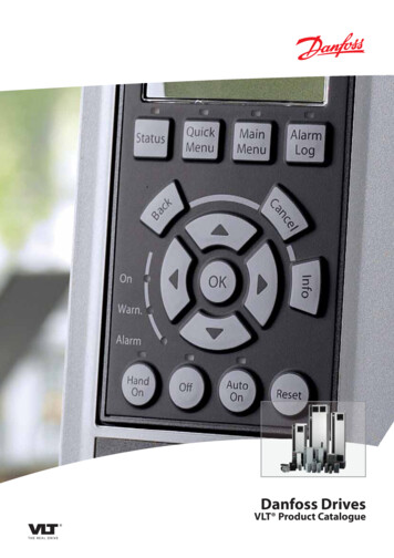
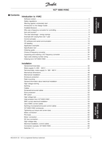
Function25-58 RunNext PumpDelay0.1-5.0 s*0.1 sTime betweenstopping the oldvariable speedpump andstarting the newappointed pump.25-84 PumpON Time0-2147483647*0View the totaloperating hoursof the connectedpumps. Can bereset by writing0.25-59 Run onMains DelayExpressionlimit *0.5 s(0.1)-5.0 sTime delaybefore a fixedspeed pump isstaged onaccording tonormal stagingsequence.25-90 PumpInterlock*[0] Off[1] On*[0] OffChoose thepump tointerlock for e.g.service. Thepump will betaken out of anypump cycling etc.25-80 CascadeStatus25-81 PumpStatusView the controlstatus for theCascadeController.0-0*0Table 1.3View the statusfor the pumpsconnected:X Disabled,O Off, D Speedcontrolled,R Mains.1.2 Installation1.2.1 Control TerminalsOFF10V/20mA IN0/4-20mA A OUT / DIG OUT10V/20mA IN10V OUTDIGI IN/OUTDIGI IN/OUTDIGI INDIGI INN18 19 27 29 42 45 50 53 54P61 68 69COMM. GNDIllustration 1.3 shows all control terminals of the frequencyconverter. Applying Start (terminal 18), connectionbetween terminal 12-27 and an analog reference (terminal53 or 54 and 55) make the frequency converter run.BUS TER.ON130BB985.101 1VLT HVAC Basic Drive Cascade ControllerVLT HVAC Basic Drive Casca.0/4-20mA A OUT / DIG OUT12 20 55 24VIllustration 1.3 Control Terminals4MI18I302 - VLT is a registered Danfoss trademarkCOM A INCOM DIG IN
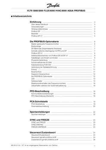
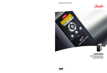
VLT HVAC Basic Drive Cascade ControllerVLT HVAC Basic Drive Casca.1 13 PhasepowerinputL1L2L3130BB984.101.2.2 Electrical OverviewUVWPEPEMotorUDC-Not present on all power sizesUDC 10Vdc50 ( 10V OUT)0-10Vdc0/4-20 mA53 (A IN)0-10Vdc0/4-20 mA54 (A IN)relay206050455 (COM A IN/OUT)42 0/4-20mA A OUT / DIG OUTrelay10345 0/4-20mA A OUT / DIG OUT02ON1 218 (DIGI IN)240V AC 3A01Bus ter.12 ( 24V OUT)ON TerminatedOFF Unterminated24V (NPN)OV (PNP)19 (DIGI IN)24V (NPN)OV (PNP)20 (COM D IN)Bus ter.27 (DIGI IN/DIGI OUT)24V29 (DIGI IN/DIGI OUT)240V AC 3A24V (NPN)OV (PNP)RS-485Interface(N PS-485) 69RS-485(P RS-485) 680V24V24V (NPN)OV (PNP)(Com RS-485 ) 61Do not connect shield to61 on 116,117 and 118 unites(PNP)-Source(NPN)-Sink0VIllustration 1.4 Electrical OverviewNOTEThere is no access to UDC- and UDC on the following units:IP20 380-480 V, 30-90 kWMI18I302 - VLT is a registered Danfoss trademark5
1 1VLT HVAC Basic Drive Cascade ControllerVLT HVAC Basic Drive Casca.1.3 Specifications1.3.1 Product General SpecificationsFrequency ConverterPK37PK75P1K5P2K2P3K0P4K0P5K5P7K5Typical shaft output [kW]0.370.751.52.23.04.05.57.511IP20 FrameH1H1H1H2H2H2H3H3H4RFI P45KP55KP75KP90KTable 1.4Frequency ConverterP15KTypical shaft output [kW]151822303745557590IP20 FrameH4H5H5H6H6H6H7H7H8RFI CoatedCoatedCoatedCoatedCoatedTable 1.56MI18I302 - VLT is a registered Danfoss trademark
1-331-351-371-391-4*Operation / DisplayBasic SettingsLanguageRegional SettingsOperating State at Power-upGridTypeAuto DC BrakingSet-up OperationsActive Set-upProgramming Set-upLink SetupsLCP Custom ReadoutCustom Readout UnitCustom Readout Min ValueCustom Readout Max ValueDisplay Text 1Display Text 2Display Text 3LCP Keypad[Hand on] Key on LCP[Auto on] Key on LCP[Off/Reset] Key on LCPCopy/SaveLCP CopySet-up CopyPasswordMain Menu PasswordLoad and MotorGeneral SettingsConfiguration ModeMotor Control PrincipleTorque CharacteristicsClockwise DirectionMotor Control BandwidthMotor SelectionMotor ConstructionDamping GainLow Speed Filter Time ConstHigh Speed Filter Time ConstVoltage filter time constMotor DataMotor PowerMotor VoltageMotor FrequencyMotor CurrentMotor Nominal SpeedMotor Cont. Rated TorqueAutomatic Motor Adaption (AMA)Adv. Motor DataStator Resistance (Rs)Stator Leakage Reactance (X1)Main Reactance (Xh)d-axis Inductance (Ld)Motor PolesAdv. Motor Data II1.4.1 Main ack EMF at 1000 RPMMotor Cable LengthMotor Cable Length FeetLoad Indep. SettingMotor Magnetisation at Zero SpeedMin Speed Normal Magnetising [Hz]U/f Characteristic - UU/f Characteristic - FLoad Depen. SettingLow Speed Load CompensationHigh Speed Load CompensationSlip CompensationSlip Compensation Time ConstantResonance DampeningResonance Dampening Time ConstantMin. Current at Low SpeedStart AdjustmentsStart DelayStart FunctionFlying StartStop AdjustmentsFunction at StopMin Speed for Function at Stop [Hz]Motor TemperatureMotor Thermal ProtectionThermistor SourceBrakesDC-BrakeDC Hold/Motor Preheat CurrentDC Brake CurrentDC Braking TimeDC Brake Cut In SpeedParking CurrentParking TimeBrake Energy Funct.Brake FunctionAC Brake, Max currentOver-voltage ControlReference / RampsReference LimitsMinimum ReferenceMaximum ReferenceReferencesPreset ReferenceJog Speed [Hz]Preset Relative ReferenceReference 1 SourceReference 2 SourceReference 3 SourceRamp 1Ramp 1 Ramp Up TimeRamp 1 Ramp Down TimeRamp 2Ramp 2 Ramp Up TimeRamp 2 Ramp Down TimeOther RampsJog Ramp TimeQuick Stop Ramp TimeLimits / 6-**6-0*6-006-016-1*6-106-116-126-136-146-15Motor LimitsMotor Speed DirectionMotor Speed Low Limit [Hz]Motor Speed High Limit [Hz]Current LimitMax Output FrequencyAdj. Warnings 2Warning Freq. LowWarning Freq. HighAdj. WarningsWarning Current LowWarning Current HighWarning Reference LowWarning Reference HighWarning Feedback LowWarning Feedback HighMissing Motor Phase FunctionSpeed BypassBypass Speed From [Hz]Bypass Speed To [Hz]Semi-Auto Bypass Set-upDigital In/OutDigital I/O modeDigital Input ModeTerminal 27 ModeTerminal 29 ModeDigital Input 29 ModeDigital InputsTerminal 18 Digital InputTerminal 19 Digital InputTerminal 27 Digital InputTerminal 29 Digital InputDigital OutputsTerminal 27 Digital OutputTerminal 29 Digital OutputOn Delay, Digital OutputOff Delay, Digital OutputRelaysFunction RelayOn Delay, RelayOff Delay, RelayPulse InputTerm. 29 Low FrequencyTerm. 29 High FrequencyTerm. 29 Low Ref./Feedb. ValueTerm. 29 High Ref./Feedb. ValueBus ControlledDigital & Relay Bus ControlAnalog In/OutAnalog I/O ModeLive Zero Timeout TimeLive Zero Timeout FunctionAnalog Input 53Terminal 53 Low VoltageTerminal 53 High VoltageTerminal 53 Low CurrentTerminal 53 High CurrentTerminal 53 Low Ref./Feedb. ValueTerminal 53 High Ref./Feedb. 48-558-568-7*8-708-728-738-748-758-798-8*Terminal 53 Filter Time ConstantTerminal 53 modeAnalog Input 54Terminal 54 Low VoltageTerminal 54 High VoltageTerminal 54 Low CurrentTerminal 54 High CurrentTerminal 54 Low Ref./Feedb. ValueTerminal 54 High Ref./Feedb. ValueTerminal 54 Filter Time ConstantTerminal 54 modeAnalog/Digital Output 45Terminal 45 ModeTerminal 45 Analog OutputTerminal 45 Digital OutputTerminal 45 Output Min ScaleTerminal 45 Output Max ScaleTerminal 45 Output Bus ControlAnalog/Digital Output 42Terminal 42 ModeTerminal 42 Analog OutputTerminal 42 Digital OutputTerminal 42 Output Min ScaleTerminal 42 Output Max ScaleTerminal 42 Output Bus ControlDrive TypeComm. and OptionsGeneral SettingsControl SiteControl SourceControl Timeout TimeControl Timeout FunctionFC Port SettingsProtocolAddressBaud RateParity / Stop BitsMinimum Response DelayMaximum Response DelayMaximum Inter-char delayFC MC protocol setPCD Write ConfigurationPCD Read ConfigurationDigital/BusCoasting SelectQuick Stop SelectDC Brake SelectStart SelectReversing SelectSet-up SelectPreset Reference SelectBACnetBACnet Device InstanceMS/TP Max MastersMS/TP Max Info Frames"I am" ServiceIntialisation PasswordProtocol Firmware versionFC Port 5014-5114-5214-5314-5514-6*14-6315-**15-0*15-00Bus Message CountBus Error CountSlave Messages RcvdSlave Error CountSlave Messages SentSlave Timeout ErrorsReset FC port DiagnosticsBus FeedbackBus Feedback 1Smart LogicSLC SettingsSL Controller ModeStart EventStop EventReset SLCComparatorsComparator OperandComparator OperatorComparator ValueTimersSL Controller TimerLogic RulesLogic Rule Boolean 1Logic Rule Operator 1Logic Rule Boolean 2Logic Rule Operator 2Logic Rule Boolean 3StatesSL Controller EventSL Controller ActionSpecial FunctionsInverter SwitchingSwitching FrequencyOvermodulationDamping Gain FactorMains On/OffFunction at Mains ImbalanceReset FunctionsReset ModeAutomatic Restart TimeOperation ModeTypecode SettingAction At Inverter FaultProduction SettingsService CodeEnergy OptimisingVT LevelAEO Minimum MagnetisationEnvironmentRFI FilterDC-Link Voltage CompensationFan ControlFan MonitorOutput FilterAuto DerateMin Switch FrequencyDrive InformationOperating DataOperating hoursVLT HVAC Basic Drive Casca.VLT HVAC Basic Drive Cascade ControllerMI18I302 - VLT is a registered Danfoss trademark1 17
ng HourskWh CounterPower Up'sOver Temp'sOver Volt'sReset kWh CounterReset Running Hours CounterAlarm LogAlarm Log: Error CodeInternalFaultReasonDrive IdentificationFC TypePower SectionVoltageSoftware VersionOrdered TypeCodeDrive Ordering NoPower Card Ordering NoLCP Id NoSW ID Control CardSW ID Power CardDrive Serial NumberPower Card Serial NumberParameter InfoDefined ParametersApplication TypeDrive IdentificationData ReadoutsGeneral StatusControl WordReference [Unit]Reference [%]Status WordMain Actual Value [%]Custom ReadoutMotor StatusPower [kW]Power [hp]Motor VoltageFrequencyMotor currentFrequency [%]Motor ThermalDrive StatusDC Link VoltageHeatsink Temp.Inverter ThermalInv. Nom. CurrentInv. Max. CurrentSL Controller StateRef. & Feedb.External ReferenceFeedback[Unit]Inputs & OutputsDigital InputTerminal 53 SettingAnalog Input AI53Terminal 54 SettingAnalog Input nalog Output AO42 [mA]Digital OutputPulse Input #29 [Hz]Relay Output [bin]Counter ACounter BAnalog Output AO45Fieldbus & FC PortFC Port REF 1Diagnosis ReadoutsAlarm WordAlarm Word 2Warning WordWarning Word 2Ext. Status WordExt. Status Word 2Info & ReadoutsFire Mode LogFireMode Log:EventDrive Closed LoopFeedbackFeedback 1 SourceFeedback 1 ConversionPI Basic SettingsPI Normal/ Inverse ControlPI Start Speed [Hz]On Reference BandwidthPI ControllerPI Anti WindupPI Proportional GainPI Integral TimePI Feed Forward FactorAppl. FunctionsSleep ModeMinimum Run TimeMinimum Sleep TimeWake-Up Speed [Hz]Wake-Up Ref./FB DiffSetpoint BoostMaximum Boost TimeSleep Speed [Hz]Broken Belt DetectionBroken Belt FunctionBroken Belt TorqueBroken Belt DelayAppl. Functions 2Fire ModeFM FunctionFM Preset ReferenceFM Alarm HandlingDrive BypassDrive Bypass FunctionDrive Bypass Delay TimeCascade ControllerSystem SettingsCascade ControllerPump CyclingFixed Lead PumpNumber of width SettingsStaging BandwidthOverride BandwidthFixed Speed BandwidthSBW Staging DelaySBW Destaging DelayOBW TimeStage FunctionStage Function TimeDestage FunctionDestage Function TimeStaging SettingsStaging ThresholdDestaging ThresholdStaging Speed [Hz]Destaging Speed [Hz]Alternation SettingsLead Pump AlternationAlternation EventAlternation Time IntervalAlternation Timer ValueAlternate if Load 50%Staging Mode at AlternationRelays per PumpRun Next Pump DelayRun on Mains DelayStatusCascade StatusPump StatusPump ON TimeServicePump InterlockDebug only - see PNU 1429 (servicecode) alsoAll debug parametersTestMonitorModeVersion And StackLCPEdit Set-upEEPROMDdataVersPowerDataVariantIDAMA RetryDAC selectionDAC scaleMOC TestUS16MOC TestS16TestMocFunctionsDC Link Power MeasurementCheckSumAnalog Input 53 (%)Analog Input 54 (%)Input Reference 1Input Reference 2Input Reference SettingFeedback (%)Fault CodeControl WordResetCountersControlActive Setup For BACnetName Of Analog Value 1 For 538-9638-9738-9838-99Name Of Analog Value 3 For BACnetName Of Analog Value 5 For BACnetName Of Analog Value 6 For BACnetName Of Binary Value 1 For BACnetName Of Binary Value 2 For BACnetName Of Binary Value 3 For BACnetName Of Binary Value 4 For BACnetName Of Binary Value 5 For BACnetName Of Binary Value 6 For BACnetName Of Binary Value 21 For BACnetName Of Binary Value 22 For BACnetName Of Binary Value 33 For BACnetBus Feedback 1 ConversionRun Stop Bus ControlInverter ETR counterRectifier ETR counterDB ErrorWarningsExtended Alarm WordAMA DebugS32AOCDebug0AOCDebug1AO42 FixedModeAO42 FixedValueDI TestCountersProtect Func. CounterHighest Lowest CoupleDB SendDebugCmdMaxTaskRunningTimeDebugInformationDB OptionSelectorEEPROM AddressEEPROM ValueLogger Time RemainLCP FC-Protocol selectMotor Power InternalMotor Voltage InternalMotor Frequency InternalLsigmaDB SimulateAlarmWarningExStatusData Logger PasswordData Logging PeriodSignal to DebugSigned Debug InfoVLT HVAC Basic Drive Casca.VLT HVAC Basic Drive Cascade Controller1 1MI18I302 - VLT is a registered Danfoss trademark
MAKING MODERN LIVING POSSIBLEwww.danfoss.com/drivesInstructionVLTp HVAC Basic DriveCascade Controller130R0267MI18I302*MI18I302*Rev. 2012-08-30
1.1.1 System Status and Operation Only when lead pump is working, the frequency converter can go into sleep mode. When the Cascade Controller is enabled, the operation status for each pump and the Cascade Controller is displayed by 25-81, Pump Status and 25-80, Cascade Status on the LCP. Cascade Controller information displayed includes: