Transcription
Danfoss DrivesVLT Product Catalogue
The leading provider of DrivesTwo thousand employees headed fromGraasten in Denmark develop, manufacture, sell and service electronic motorcontrols in more than one hundredcountries.Manufacturing takes place in USA –Especially the high power products –andin Asia, but the major production takesplace in the plants in Graasten, Denmark,where half of the staff are employed.Danfoss Bauer geared motors aremanufactured in Esslingen, Germany.The success of Danfoss is due to thestrong combination of technology andapplication knowledge throughout theworld combined with a highly sophisticated set-up of product development,supply chain, logistics and on-sitepresence anywhere on the globe.Our customers are closely involved duringevery stage of design and development,specifying their needs in terms of featuresand user interface. Danfoss Drivesdedicates itself to every step in everyprocess until the customer has the drive inhand.The developers at Danfoss Drives havefully adopted modular principles indevelopment as well as design, production and configuration. Each function isdeveloped in parallel on dedicatedtechnology platforms and interfacesbetween the elements are carefullydefined. This allows development to takeplace for each element in parallel,reducing time to market and ensuringthat customers always enjoy the benefitsof recently developed features.This unique modular concept is also thebasis for a highly automated qualitymanufacturing process, where DanfossDrives takes responsibility for everyelement – starting with the essential semiconductor power modules. PowerModules are produced in Danfoss SiliconPower in Schleswig, Germany. High qualitystandards and efficient manufacturingfacilities makes Danfoss Silicon Powermodules in great demand within industries that provide highly automatedpower-applications like the automotivesector.When it comes to quality, delivery andcooperation, Danfoss makes highdemands on their suppliers – both frominside and outside of the group.Due to an unsurpassed level of automation Danfoss can produce a customerconfigured drive from 1.6 million possibleconfigurations in a manufacturing time oftwo hours. The unique string type codethat fully defines the drive can easily beobtained throughout the world by use ofthe internet; it determines the configuration of all elements of the drive, bothelectronics and hardware. Once thisunique configuration is passed to theproduction departments the manufacturing process can begin. Testing is carriedout at all stages of the process and beginswith optical checks of the PCBs to ensurethat components are inserted correctly.Once the PCBs are fully assembled they allmust pass an automatic in-circuit test.After assembly is complete all drives arefully tested on motor loads.During the drives manufacturing cycle thecorrect manual is being printed and madeavaiable for packing. By the use of thisprocess we ensure that not only thecorrect language but the very latestversion of the manual is always producedand shipped with the correct drive. Just intime delivery is a reality.Once the drive is shipped, one of morethan 60 local Danfoss sales companies canensure that the drive is correctly installedand commissioned. Once the equipmentis commissioned, the level of service thecustomer requires can be defined in anagreement with the customer accordingto his specific needs. At every step of theway, from development of new technologies and features, the mass production ofhighly customised products, to installation and service, Danfoss Drives has onlythe customer in mind.2
ContentsVLT Micro DriveVLT 8000 AQUAThe VLT Micro Drive is a general purposedrive that can control AC motors up to 7.5 kW.It’s a small drive with maximum strength andreliability.Page 4The VLT 8000 has been designed to operatein the water and wastewater market.Page 20VLT 2800 SeriesVLT High Power DrivesAn extremely compact series of drivesprepared for side-by-side mounting anddeveloped specifically for the low powermarket.Page 6VLT series high power drives reduce energyusage in driven equipment. High efficiencyof the VLT series also drives down energy costsin cooling requirements.Page 22VLT AutomationDriveVLT Decentral FCD 300The VLT AutomationDrive representsa single drive concept to control the entirerange of operations from standard to servo onany machine or production line.Page 8The VLT Decentral FCD 300 is acomplete frequency converterdesigned for decentral mounting.Page 24VLT 5000VLT DriveMotor FCM 300The perfect match for an abundanceof industrial applications.Page 10The VLT FCM 300 Series is a very compactalternative to the traditional solution witha VLT frequency converter and motor asseparate units.Page 26VLT 5000 FluxVLT Soft Starter MCD 100The VLT 5000 Flux is an extension of theexisting VLT 5000 series. Full torque controlalso under acceleration as well as very accuratespeed control even at low speed or standstillcan now be obtained.Page 12The VLT Soft Starter MCD 100 providessoft start features for low power applications1.1 – 11 kW.Page 28VLT HVAC DriveVLT Compact Starter MCD 200The VLT HVAC Drive integrates and communicates seamlessly with all HVAC devices,mastered by Building Management Systems oras stand-alone unit.Page 14The MCD 200 is a compact and cost effectivesoft starter range for applications where directon-line starting is undesirable. MCD 200 is dueto its size and functionality a good alternative toother reduced voltage starting methods such asstart/delta starters.Page 30VLT 6000 HVACVLT Soft Starter MCD 3000The VLT 6000 HVAC is fully dedicatedto the optimum operation of HVACapplications. It offers energy savingsand user-friendliness, and all functionsare built in.Page 16The MCD 3000 is a total motor starter providingall the best in soft starter functionality. It offershigh end functionality whether it is for starting,stopping or protection of motor or application.Page 32VLT AQUA DriveVLT Harmonic FilterAHF 005/010VLT AQUA Drive the perfect match for pumpsand blowers in modern water and wastewatersystems.Page 18Connecting the AHF 005/010 harmonic filterin front of a Danfoss frequency converter isan easy and effective way to reduce harmonicdistortion.Page 343
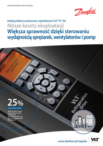
VLT Micro DriveThe VLT Micro Drive is a generalpurpose drive that can controlAC motors up to 7.5 kW. It’s a smalldrive with maximum strength andreliability.RoHS compliantThe VLT Micro Drive is manufacturedwith respect for the environment, andit complies with the RoHS Directive.The perfect match for: Industrial appliances HVAC applications OEMPower range:1 phase 200–240 V AC . 0.18–2.2 kW3 phase 200–240 V AC . 0.25–3.7 kW3 phase 380–480 V AC . 0.37–7.5 kWCoated PCB standardFor harsh environments.Mount4Connect.and the motor is running
SpecificationsMains supply (L1, L2, L3):Supply voltage .1 x 200– 240 V 10%, 3 x 200– 240 V 10%3 x 380 – 480 V 10%Output data (U, V, W):Output voltage. .0 – 100% of supply voltageOutput frequency . 0 – 200 Hz (VVC mode), 0 – 400 Hz (U/f mode)Switching on output .UnlimitedRamp times. 0.05 – 3600 secDigital inputs:Programmable inputs .5Logic .PNP or NPNVoltage level . 0 – 24 VPulse inputs:Programmable pulse inputs .1*Voltage level . 0 – 24 V DC (PNP positive logic)Pulse input frequency.20 – 5000 Hz* One of the digital inputs can be used for pulse inputs.Analog output:Analog inputs .2Modes . 1 current/1 voltage or currentVoltage level .0 – 10 V (scaleable)Current level . 0/4 – 20 mA (scaleable)Analog output:Programmable analog outputs .1Current range at analog output .0/4 –20 mARelay outputs:Programmable relay outputs . 1 (240 VAC, 2 A)Approvals:CE, C-tick, ULFieldbus communication: FC Protocol Modbus RTUOrdering numbers200 3.74.05.57.51.21.52.24.26.89.615.21 ph.400 V3 ph.Current[I-nom.]3 ph.1.22.23.75.37.2132F 0017132F 0018132F 0020132F 0022132F 002491215.5132F 0026132F 0028132F 0030132F 0001132F 0002132F 0003132F 0005132F 0007132F 0008132F 0009132F 0010132F 0012132F 0014132F 0016Micro drives from 1.5 kW and uphave built in brake chopper5
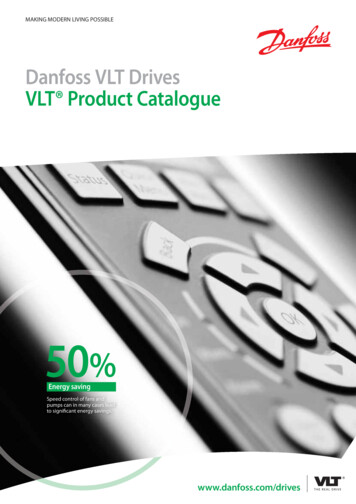
VLT 2800 SeriesThe VLT 2800 series are among thesmallest multi purpose drives in themarket, designed for space savingside-by-side mounting.Choose to have it with built-in MotorCoils, RFI filter, LC 1B filters e.g.The VLT 2800 was designed as anadvanced and versatile drive, yet easyto operate. Quick menu Includes allparameters basically needed forcommissioning the drive. Offers fastinstallation and service.Flexible mountingProduct safety 100 % short-circuit proof 100 % earth fault protection Mains transient protection Switching on input Switching on output Galvanic isolation Designed according to EN501786Precise stopConventional units rely on a periodicscan of the Digital Inputs, which initiates the Stop command. This can result in uneven delays while the Drivescans all the other parts of the program taking up to perhaps 10 ms. Thisis a disadvantage in typical packagingapplications. For a conveyor operating at a speed of 1 metre/second, thatgives a deviation of 10 mm. In theVLT 2800, the Stop command is anInterrupt rather than part of the scan.The repeating precision is improved.The deviation is only 1 mm in theexample used above.Counter Precise StopAfter the start signal is received,the VLT 2800 operates until the userprogrammed number of pulses isseen at terminal 33.A Stop signal is generated and thenormal stop ramp is used. The counterstop signal is then re-armed andready again for a new start command.The pulse input is designed to handle24 V push-pull pulses from an encoder with 1024 ppr. The maximum pulserate is 67,600 Hz.
SpecificationsMains supply (L1, L2, L3):Control card, digital/frequency output:Supply voltage:VLT 2803-2815 220-240 V (N, L1).1 x 220/230/240 V 10%VLT 2803-2840 200-240 V .3 x 200/208/220/230/240 V 10%VLT 2805-2882 380-480 V .3 x 380/400/415/440/480 V 10%Supply frequency .50/60 Hz 3 HzMax. imbalance on supply voltage . 2.0% of rated supply voltageTrue Power Factor (λ).0.90 nominal at rated loadDisplacement Power Factor (cosф) .near unity ( 0.98)Number of connections at supply input L1, L2, L3 . 2 times/min.Max. short-circuit value. .100,000 ANumber of programmable digital/pulse outputs . 1 pcs.Terminal number .46Voltage level at digital/frequency output .0 – 24 V DC (O.C PNP)Max. output current at digital/frequency output .25 mAMax. load at digital/frequency output. 1 kΩMax. capacity at frequency output . 10 nFMinimum output frequency at frequency output . 16 HzMaximum output frequency at frequency output.10 kHzAccuracy on frequency output.Max. error: 0.2% of full scaleResolution on frequency output . 10 bitOutput data (U, V, W):The digital output is galvanically isolated from the supply voltage (PELV)and other high-voltage terminals.Output voltage. .0 – 100% of supply voltageOutput frequency . 0.2 – 132 Hz, 1 – 1000 HzRated motor voltage, 200-240 V units . 200/208/220/230/240 VRated motor voltage, 380-480 V units . 380/400/415/440/460/480 VRated motor frequency .50/60 HzSwitching on output. .UnlimitedRamp times. 0.02 – 3600 sec.Torque characteristics:Starting torque Constant torque) .160% in 1 min.*Starting torque (Variable torque) .160% in 1 min.*Starting torque (parameter 119 High starting torque ). 180% for 0.5 sec.*Overload torque (Constant torque) . 160%*Overload torque (Variable torque) . 160%*Control card, analog output:Number of programmable analog outputs . .1Terminal number .42Current range at analog output . 0/4 – 20 mAMax. load to common at analog output .500 ΩAccuracy on analog output .Max. error: 1.5% of full scaleResolution on analog output .10 bitThe analog output is galvanically isolated from the supply voltage (PELV)and other high-voltage terminals.Control card, 24 V DC output:Terminal number .12Max. load . .130 mA*Percentage relates to frequency converter’s nominal current.The 24 V DC supply is galvanically isolated from the supply voltage (PELV),but has the same potential as the analogue and digital inputs and outputs.Control card, digital inputs:Control card, 10 V DC output:Number of programmable digital inputs .5Terminal number .18, 19, 27, 29, 33Voltage level. . 0 – 24 V DC (PNP positive logic)Voltage level, logic ’0’ . 5 V DCVoltage level, logic ’1’ . 10 V DCMaximum voltage on input .28 V DCInput resistance, Ri (terminals 18, 19, 27, 29) . approx. 4 kΩInput resistance, Ri (terminal 33) . approx. 2 kΩAll digital inputs are galvanically isolated from the supply voltage (PELV)and other high-voltage terminals.Control card, analog inputs:Number of analog voltage inputs .1Terminal number .53Voltage level. .0 – 10 V DC (scaleable)Input resistance, Ri . .approx. 10 kΩMax. voltage .20 VNumber of analog current inputs.1Terminal number . 60Current level . 0/4 – 20 mA (scaleable)Input resistance, Ri . approx. 300 ΩMax. current .30 mAResolution for analog inputs .10 bitAccuracy of analog inputs. Max. error 1% of full scaleScan interval. .13.3 msecThe analog inputs are galvanically isolated from the supply voltage (PELV)and other high-voltage terminals.Control card, pulse inputs:Number of programmable pulse inputs .1Terminal number .33Max. frequency at terminal 33 .67.6 kHz (Push-pull)Max. frequency at terminal 33 .5 kHz (open collector)Min. frequency at terminal 33 . 4 HzVoltage level. . 0 – 24 V DC (PNP positive logic)Voltage level, logic ’0’ . 5 V DCVoltage level, logic ’1’ . 10 V DCMaximum voltage on input .28 V DCInput resistance, Ri . approx. 2 kΩScan interval.13.3 msecResolution .10 bitAccuracy (100 Hz – 1 kHz) terminal 33 . Max. error: 0.5% of full scaleAccuracy (1 kHz – 67.6 kHz) terminal 33 .Max. error: 0.1% of full scaleTerminal number .50Output voltage . 10.5 V 0.5 VMax. load .15 mAThe 10 V DC supply is galvanically isolated from the supply voltage (PELV)and other high-voltage terminals.Control card, RS 485 serial communication:Terminal number .68 (TX , RX ), 69 (TX-, RX-)Terminal number 67 . 5 VTerminal number 70 .Common for terminals 67, 68 and 69Full galvanic isolation.Relay outputs:Number of programmable relay outputs .1Terminal number, control card .1-3 (break), 1-2 (make)Max. terminal load (AC) on 1-3, 1-2, control card . 240 V AC, 2 AMin. terminal load on 1-3, 1-2, control card 24 V DC 10 mA, 24 V AC 100 mAThe relay contact is separated from the rest of the circuit by strengthened isolation.Cable lengths and cross sections:Max. motor cable length:Screened/armoured cable . 40 mUnscreened/unarmoured cable. 75 mScreened/armoured cable and motor coil. .100 mUnscreened/unarmoured cable and motor coil .200 mScreened/armoured cable and RFI/1B filter . 200 V, 100 mScreened/armoured cable and RFI/1B or RFI 1B/LC filter . 400 V, 25 mMax. cross section to control wires,rigid wire .1.5 mm2/16 AWG (2 x 0.75 mm2)Max. cross section to control cables,flexible cable .1 mm2/18 AWGMax. cross section to control cables,cable with enclosed core . 0.5 mm2/20 AWGWhen complying with EN 55011 1A and EN 55011 1B the motor cable mustin certain instances be reduced.The pulse input (terminal 33) is galvanically isolated from the supply voltage (PELV)and other high-voltage terminals.7
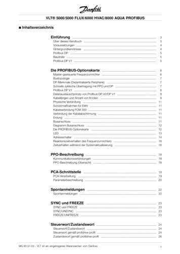
VLT AutomationDriveThe VLT AutomationDrive FC 300 isextremely configurable and runs anymotor in any application and anymachine for manufacturing.Specify your requirements and haveyour drives tailor-made within acouple of hours – for the cost of massproduced stockware.Range:0.25 – 37 kW . (200 – 240 V)0.75 – 1000 kW . (525 – 600 V)11 – 1000 kW . (600 – 690 V)Plug and playYou don’t have to disconnect wires inthe cage clamps to disconnect theVLT AutomationDrive. Just unplugthe cage clamp instead.Pluggable optionsThe bus option, as shown above,ready to plug in underneath the frontpanel. It can be turned upside downif you prefer the cable to enter fromthe top.Remote commissioningLocal control of the VLT AutomationDrive is done by a local control panel.This is plugged in directly or connected through a cable.USB pluggableThe VLT AutomationDrive can beremotely commissioned and monitored through a USB pluggable cableor bus communication. Specialsoftware is available: Wizards, Datatransfer tool, VLT Set-up SoftwareMCT 10.8One-Drive conceptOne-Drive concept covering thewhole production or machine is amajor benefit in commissioning,operating and maintaining theequipment. The make-throughmodular design makes upgrade easyas well as adaptation of futurefeatures. On-board manuals makeoperation easy and the built in SmartLogic Control allows for basic programming covering many commonPLC functions.
SpecificationsMains supply (L1, L2, L3):Relay outputs:Supply voltage .200-240 V 10%Supply voltage .FC 301: 380-480 V / FC 302: 380-500 V 10%Supply voltage . FC 302: 525-600 V 10%Supply frequency .50/60 HzMax. imbalance between mains phases . 3.0% of rated supply voltageTrue Power Factor (λ).0.92 nominal at rated loadDisplacement Power Factor (cosф) near unity. . ( 0.98)Switching on input supply L1, L2, L3 (power-ups) .maximum 2 times/min.Environment according to EN60664-1overvoltagecategory III/pollution degree 2.Programmable relay outputs . FC 301: 1 / FC 302: 2Terminal number,power card. .1-3 (break), 1-2 (make), 4-6 (break), 4-5 (make)Max. terminal load on 1-3 (break), 1-2 (make),4-6 (break) power card . 240 V AC, 2 AMax. terminal load (AC) on 4-5 (make) power card . 400 V AC, 2 AMin. terminal load on 1-3 (break), 1-2 (make),4-6 (break), 4-5 (make) power card . 24 V DC 10 mA, 24 V AC 100 mAEnvironment according to EN 60664-1 overvoltagecategory III/pollution degree 2.The unit is suitable for use on a circuit capable of delivering not more than 100.000 RMSsymmetrical Amperes, 240/500/600 V maximum.The relay contacts are galvanically isolated from the rest of the circuit by reinforced isolation (SELV).Digital inputs:Programmable digital inputs . FC 301: 4 (5) / FC 302: 4 (6)Terminal number .18, 19, 271), 291), 32, 33, 372)Logic .PNP or NPN3)Voltage level . 0 – 24 V DCVoltage level, logic’0’ PNP. 5 V DCVoltage level, logic’1’ PNP. 10 V DCVoltage level, logic ’0’ NPN3) . 19 V DCVoltage level, logic ’1’ NPN3) . 14 V DCMaximum voltage on input .28 V DCInput resistance, Ri . approx. 4 kΩAll digital inputs are galvanically isolated from the supply voltage (PELV)and other high-voltage terminals.1) Terminals 27 and 29 can also be programmed as digital outputs.2) Terminal 37 is only available in FC 302. It can only be used as “safe stop” input.Terminal 37 is suitable for category 3 installations according to EN 954-1(safe stop according to category 0 EN 60204-1).3) Exception: Terminal 37 is fixed PNP logic.Analogue inputs:Number of analogue inputs .2Terminal number .53, 54Modes . Voltage or currentMode select .Switch S201 and switch S202Voltage mode .Switch S201/switch S202 OFF (U)Voltage level . FC 301: 0 to 10 / FC 302: -10 to 10 V (scaleable)Input resistance, Ri . approx. 10 kΩMax. voltage . 20 VCurrent mode . Switch S201/switch S202 ON (I)Current level . 0/4 to 20 mA (scaleable)Input resistance, Ri . approx. 200 ΩMax. current .30 mAResolution for analogue inputs . .10 bit ( sign)Accuracy of analogue inputs.Max. error 0.5% of full scaleBandwidth.FC 301: 20 Hz / FC 302: 100 HzThe analogue inputs are galvanically isolated from the supply voltage (PELV)and other high-voltage terminals.Pulse/encoder inputs:Programmable pulse/encoder inputs .2/1Terminal number pulse/encoder. . 29, 331) / 18, 32, 332)Max. frequency at terminal 18, 29, 32, 33 .110 kHz (Push-pull driven)Max. frequency at terminal 18, 29, 32, 33 .5 kHz (open collector)Min. frequency at terminal 18, 29, 32, 33.4 HzVoltage level .see section on Digital inputMaximum voltage on input .28 V DCInput resistance, Ri .
VLT 6000 HVAC The VLT 6000 HVAC is fully dedicated to the optimum operation of HVAC applications. It off ers energy savings and user-friendliness, and all functions are built in. Page 16 VLT AQUA Drive VLT AQUA Drive the perfect match for pumps and blowers in modern water and wastewater systems. Page 18 VLT Decentral FCD 300 The VLT .