Transcription
VLT 6000 HVAC SeriesContentsIntroduction to HVACSoftware versionSafety regulationsWarning against unintended startIntroduction to Operating InstructionsAvailable literatureVLT 6000 Advantages in a HVAC installationControl principleAEO - Automatic Energy OptimizationExample of application - Speed control of fan in ventilation systemExample of application - Constant pressure regulation in water supply systemFire modeCE labellingPC software and serial communicationUnpacking and ordering a VLT frequency converterType code ordering number stringOrdering formInstallationMains supply (L1, L2, L3)Max. imbalance of supply voltageTechnical data, mains supply 3 x 200-240VTechnical data, mains supply 3 x 380-460VTechnical data, mains supply 3 x 525-600 VFusesMechanical dimensionsMechanical installationGeneral information about electrical installationHigh voltage warningEarthingCablesScreened/armoured cablesExtra protection with regard to indirect contactRFI switchHigh voltage testHeat emission from VLT 6000 HVACVentilation of integrated VLT 6000 HVACEMC correct electrical installationUse of EMC-correct cablesElectrical installation - earthing of control cablesElectrical installation, enclosuresTightening-up torque and screw sizesMains connectionMotor connectionDirection of motor rotationMotor cablesMotor thermal protectionMG.61.A6.02 - VLT is a registered Danfoss 424649494949505051545454545758596666666767681
VLT 6000 HVAC SeriesEarth connectionInstallation of 24 Volt external DC supplyDC bus connectionHigh-voltage relayControl cardElectrical installation, control cablesSwitches 1-4Bus connectionConnection examples, VLT 6000 HVACProgrammingControl unit LCPControl keysfor parameter setupIndicator lampsLocal controlDisplay modeNavigation between display modesChanging dataManual initialisationQuick MenuOperation and Display 001-017The Setup configurationSetup of user-defined readoutLoad and Motor 100-117ConfigurationMotor power factor (Cos ø)Reference handlingReference typeInputs and outputs 300-365Analogue inputsAnalog/digital outputsRelay outputsApplication functions 400-427Sleep modePID for process controlPID overviewFeedback handlingService functions 600-631Electrical installation of the relay cardDescription of Real Time ClockAll about VLT 6000 HVACStatus messagesList of warnings and alarmsAggressive environmentsCalculation of resulting referenceGalvanic isolation (PELV)Earth leakage currentExtreme running 1144144146153153154154155MG.61.A6.02 - VLT is a registered Danfoss trademark
VLT 6000 HVAC SeriesPeak voltage on motorSwitching on the inputAcoustic noiseDerating for ambient temperatureDerating for air pressureDerating for running at low speedDerating for long motor cables or cables with larger cross-sectionDerating for high switching frequencyVibration and shockAir humidityEfficiencyMains supply interference/harmonicsPower factor(Emission, Immunity)EMC ImmunityDefinitionsParameter overview and factory settingsIndexMG.61.A6.02 - VLT is a registered Danfoss 21651671691763
VLT 6000 HVAC SeriesVLT 6000 HVACOperating InstructionsSoftware version: 3.2xThese Operating Instructions can be used for all VLT 6000 HVAC frequency converters with software version3.2x.The software version number can be seen from parameter 624.4MG.61.A6.02 - VLT is a registered Danfoss trademark
VLT 6000 HVAC Series7.Reliable galvanic isolation (PELV) is notcomplied with if the RFI switch is placed inOFF position. This means that all control in and outputs can only be considered low-voltage terminals with basic galvanic isolation.8.Please note that the frequency converter hasmore voltage inputs than L1, L2 and L3, whenthe DC-bus terminals are used.Check that all voltage inputs have been disconnected and that the necessary time haspassed before repair work is commenced.Installation in high altitudes:By altitudes above 2km, please contactDanfoss Drives regarding PELVWarning against unintended startSafety regulations1.The frequency converter must be disconnected from mains if repair work is to be carriedout. Check that the mains supply has beendisconnected and that the necessary timehas passed before removing motor andmains plugs.2.The [OFF/STOP] key on the control panel ofthe frequency converter does not disconnectthe equipment from mains and is thus not tobe used as a safety switch.3.4.5.6.Correct protective earthing of the equipmentmust be established, the user must be protected against supply voltage, and the motormust be protected against overload in accordance with applicable national and localregulations.The earth leakage currents are higher than3.5 mA.Protection against motor overload is includedin the factory setting. Parameter 117, Motorthermal protection default value is ETR trip 1.Note: The function is initialised at 1.0 x ratedmotor current and rated motor frequency(see parameter 117, Motor thermal protection).1.The motor can be brought to a stop by meansof digital commands, bus commands, references or a local stop, while the frequencyconverter is connected to mains.If personal safety considerations make it necessary to ensure that no unintended startoccurs, these stop functions are not sufficient.2.While parameters are being changed, themotor may start. Consequently, the stop key[OFF/STOP] must always be activated, following which data can be modified.3.A motor that has been stopped may start iffaults occur in the electronics of the frequency converter, or if a temporary overload or afault in the supply mains or the motor connection ceases.Use on isolated mainsSee section RFI Switch regarding use on isolatedmains.It is important to follow the recommendations regarding installation on IT-mains, since sufficient protectionof the complete installation must be observed. Not taking care using relevant monitoring devices for ITmains may result in damage.Do not remove the plugs for the motor andmains supply while the frequency converterMG.61.A6.02 - VLT is a registered Danfoss trademark5Introduction to HVACThe voltage of the frequency converter isdangerous whenever the equipment isconnected to mains. Incorrect installationof the motor or the frequency convertermay cause damage to the equipment, serious personal injury or death.Consequently, the instructions in thismanual, as well as national and local rulesand safety regulations, must be compliedwith.is connected to mains. Check that the mainssupply has been disconnected and that thenecessary time has passed before removingmotor and mains plugs.
VLT 6000 HVAC SeriesWarning:Touching the electrical parts may be fatal - even after the equipment has been disconnected from mains.VLT 6002 - 6005, 200-240 V:wait at least 4 minutesVLT 6006 - 6062, 200-240 V :wait at least 15 minutesVLT 6002 - 6005, 380-460 V:wait at least 4 minutesVLT 6006 - 6072, 380-460 V:wait at least 15 minutesVLT 6102 - 6352, 380-460 V:wait at least 20 minutesVLT 6402 - 6602, 380-460 V:wait at least 40 minutesVLT 6002 - 6006, 525-600 V:wait at least 4 minutesVLT 6008 - 6027, 525-600 V:wait at least 15 minutesVLT 6032 - 6072, 525-600 V:wait at least 30 minutesVLT 6102 - 6402, 525-600 V:wait at least 20 minutesVLT 6502 - 6652, 525-600 V:wait at least 30 minutes6MG.61.A6.02 - VLT is a registered Danfoss trademark
Introduction to HVACVLT 6000 HVAC SeriesMG.61.A6.02 - VLT is a registered Danfoss trademark7
VLT 6000 HVAC SeriesIntroduction to Operating InstructionsThese Operating Instructions are a tool intended for persons who are to install, operate and program the VLT6000 HVAC.A VLT 6000 HVAC comes with Operating Instructions as well as Quick Setup Guide. In addition, a Design Guidecan be ordered for use when designing installations that will include a VLT 6000 HVAC. See Available literature.Operating Instructions:These are instructions in how to ensure optimum mechanical and electricalinstallation, commissioning and service. The Operating Instructions alsoinclude a description of the software parameters, thereby enabling easyadaptation of the VLT 6000 HVAC to your application.Quick Setup Guide:Helps you to quickly install and commission the VLT 6000 HVAC.Design Guide:Used when designing installations that include a VLT 6000 HVAC. The Design Guide gives detailed information about VLT 6000 HVAC and HVACinstallations, including a selection tool to enable you to choose the right VLT6000 HVAC with its relevant options and modules. The Design Guide alsocontains examples of the most common HVAC applications. Furthermore,the Design Guide has all information relating to serial communication.These Operating Instructions are divided into four sections with information about VLT 6000 HVAC.Introduction to HVAC:This section tells you the advantages you can obtain by using a VLT 6000HVAC - such as AEO, Automatic Energy Optimization, RFI filters and otherHVAC-relevant functions. This section also contains examples of application as well as information about Danfoss and CE-labelling.Installation:This section tells you how to carry out mechanically correct installation ofthe VLT 6000 HVAC. In addition, this section includes a description of howto ensure that the installation of your VLT 6000 HVAC is EMC-correct. Furthermore, a list is given of mains and motor connections, together with adescription of the control card terminals.Programming:This section describes the control unit and the software parameters for theVLT 6000 HVAC. Also included is a guide to the Quick Setup menu, whichallows you to get started on your application very quickly.All about VLT 6000 HVACThis section gives information about status, warning and error messagesfrom the VLT 6000 HVAC. Additionally, information is given on technicaldata, service, factory settings and special conditions.Indicates a general warningNB!Indicates something to be noted by thereaderIndicates a high-voltage warning8MG.61.A6.02 - VLT is a registered Danfoss trademark
VLT 6000 HVAC SeriesPlease also refer to our web site http://drives.danfoss.com for information about new literature.Supplied with the unit:Operating instructionsQuick SetupHigh Power Introduction n with VLT 6000 HVAC:Profibus ManualMetasys N2 ManualLonWorks ManualLandis/Staefa Apogee FLN ManualModbus RTU ManualDeviceNet MG.10.SX.YYMG.50.HX.YYInstructions for VLT 6000 HVAC:LCP Remote Kit IP20LCP Remote Kit IP54LC-filterIP20 terminal coverVarious literature for VLT 6000 HVAC:Operating InstructionsDesign GuideData sheetVLT 6000 HVAC Cascade ControllerX version MG.60.AX.YYMG.61.BX.YYMD.60.AX.YYMG.60.IX.YYYY language versionVLT 6000 Advantages in a HVAC installation One advantage involved in using a VLT 6000 HVAC isthat this unit has been designed to regulate the speedof fans and rotary pumps while consuming the smallestpossible amount of energy. Consequently, if a VLT6000 HVAC is used in a HVAC installation, optimumenergy savings are guaranteed, since less energy isused with a frequency converter than with the traditional HVAC regulation principles. Another advantagein using the VLT 6000 HVAC is that regulation is improved and can easily adapt to a new flow or pressurerequirement in an installation. The use of a VLT 6000HVAC offers the following additional advantages:All unit types, except 525-600 V units, areavailable with an integral RFI filter, complyingwith EN 55011 class A1 in the case of a 150m screened/armoured motor cable and EN55011 class B in the case of a screened/armoured motor cable up to 50 m long. User-friendly design, which makes VLT 6000HVAC easy to install, both mechanically andelectrically. Detachable LCP control panel with Hand-OffAuto buttons and a graphics display of localspeed. High starting torque owing to Automatic Energy Optimization (AEO). Automatic Motor Adaptation (AMA) ensuresoptimum motor utilisation. Integral PID regulator with option of connecting two feedback signals (in connection withzoning), as well as setting of two set-points. VLT 6000 HVAC has been designed forHVAC applications. A wide power range - from 1.1-500 kW unitswith a unique design. IP 20 and IP 54 enclosures that can be mounted side by side. For power sizes 90kW ( 30kW for 200 V) IP 00 is also available.MG.61.A6.02 - VLT is a registered Danfoss trademark9Introduction to HVACAvailable literatureBelow is a list of the literature available for VLT 6000HVAC. It must be noted that there may be deviationsfrom one country to the next.
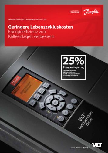
VLT 6000 HVAC Series Sleep mode, which automatically turns themotor off, e.g. when there is no need for morepressure or flow in a system. The "flying start" function enables the unit tocatch a rotating fan. Automatic ramp up/down to ensure that theVLT 6000 HVAC will not trip during acceleration or deceleration.Control principleA frequency converter rectifies AC voltage from mainsinto DC voltage, after which this DC voltage is converted into a AC current with a variable amplitude andfrequency.1. Mains voltage3 x 200 - 240 V AC, 50 / 60 Hz.3 x 380 - 460 V AC, 50 / 60 Hz.3 x 525 - 600 V AC, 50 / 60 Hz.2. RectifierA three-phase rectifier bridge that rectifies AC currentinto DC current.3. Intermediate circuitDC voltage 1.35 x mains voltage [V]. All standard units have three integral, serialprotocols - RS 485 FC protocol, Johnson'sMetasys N2 and Landis/Staefa Apogee FLN.Communication option cards that can be connected are LonWorks, DeviceNet, ModbusRTU and Profibus.The motor is thus supplied with variable voltage andfrequency, which enables infinitely variable speedcontrol of three-phased, standard AC motors.5. Intermediate circuit capacitorsEven out the intermediate circuit voltage.6. InverterConverts DC voltage into variable AC voltage with avariable frequency.7. Motor voltageVariable AC voltage, 0-100% of mains supply voltage.4. Intermediate circuit coilsEven out the intermediate circuit voltage and reducethe harmonic current feedback to the mains supply.8. Control cardThis is where to find the computer that controls the inverter which generates the pulse pattern by which theDC voltage is converted into variable AC voltage witha variable frequency.10MG.61.A6.02 - VLT is a registered Danfoss trademark
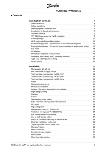
VLT 6000 HVAC SeriesAEO - Automatic Energy OptimizationIntroduction to HVACNormally, the U/f characteristics have to be set on thebasis of the expected load at different frequencies.However, knowing the load at a given frequency in aninstallation is often a problem. This problem can besolved by using a VLT 6000 HVAC with its integral Automatic Energy Optimization (AEO), which ensuresoptimum energy utilization. All VLT 6000 HVAC unitsfeature this function as a factory setting, i.e. it is notnecessary to adjust the frequency converter U/f ratioin order to obtain maximum energy savings. In otherfrequency converters, the given load and voltage/frequency ratio (U/f) must be assessed to carry out correct setting of the frequency converter.Using Automatic Energy Optimization (AEO), you nolonger need to calculate or assess the system characteristics of the installation, since Danfoss VLT 6000HVAC units guarantee optimum, load-dependent energy consumption by the motor at all times.The figure on the right illustrates the working range ofthe AEO function, within which energy optimization isenabled.If the AEO function has been selected in parameter101, Torque characteristics, this function will be constantly active. If there is a major deviation from theoptimum U/f ratio, the frequency converter will quicklyadjust itself.Advantages of the AEO function Automatic energy optimization Compensation if an oversize motor is used AEO matches operations to daily or seasonalfluctuations Energy savings in a constant air volume system Compensation in the oversynchronous working range Reduces acoustic motor noiseMG.61.A6.02 - VLT is a registered Danfoss trademark11
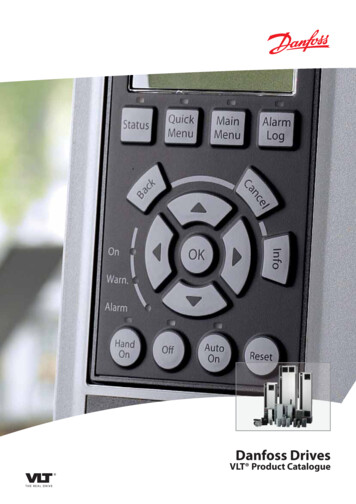
VLT 6000 HVAC SeriesExample of application - Speed control of fan inventilation systemThe AHU installation is able to distribute air throughoutthe building or to one or several parts of a building.Normally, an AHU installation consists of a fan and amotor that supply air, a fan scroll and a duct systemwith filters. If centralised air distribution is applied, theefficiency of the installation will increase and majorenergy savings can be made.A VLT 6000 HVAC enables excellent control and monitoring, thereby ensuring perfect conditions in thebuilding at all times.Set the following parameters:ConfigurationPar. 100Warning: Low current, ILOWPar. 221Warning: High frequency, f HIGHPar. 224Par. 300Terminal 16 Digital inputsPar. 302Terminal 18 Digital inputsPar. 308Terminal 53, analogue input voltagePar. 309Terminal 53, min. scalingPar. 310Terminal 53, max. scalingPar. 319OutputPar. 323Relay 1Par. 326Relay 2Par. 409Function at no load12This example shows an application with Run permissive, warning against no load and warning for filterchange.The Run permissive function ensures that the frequency converter will not start the motor until the dischargedamper has opened. If the V-belt to the fan breaks andif the filter is to be changed, this application will alsogive a warning on an output.Open loop [0]Depends on unitRun permissive [8]Start [1]Reference [1]0v10 vOutput frequency greater than fHIGH par. 224Start command active [27]Alarm or warning [12]Warning [1]MG.61.A6.02 - VLT is a registered Danfoss trademark
Example of application - Constant pressure regulation in water supply systemThe demand for water from waterworks varies considerably during the course of a day. In the night, practically no water is used, while in the morning and in theevening the consumption is high. In order to maintaina suitable pressure in the water supply lines in relationto the current demand, the water supply pumps areequipped with speed control. The use of frequencyconverters enables the energy consumed by thepumps to be kept at a minimum, while optimizing thewater supply to consumers.Set the following parameters:ConfigurationPar. 100Par. 205Maximum referencePar. 302Terminal 18 Digital inputsPar. 314Terminal 60, analog input currentPar. 315Terminal 60, min. scalingPar. 316Terminal 60, max. scalingPar. 403Sleep mode timerPar. 404Sleep frequencyPar. 405Wake-up frequencyPar. 406Boost setpointPar. 413Minimum feedbackPar. 414Maximum feedbackPar. 415Process unitsPar. 418Setpoint 1Par. 420PID normal/inverse controlPar. 423PID proportional gainPar. 424PID integration timePar. 427PID low pass filterMG.61.A6.02 - VLT is a registered Danfoss trademarkA VLT 6000 HVAC with its integral PID controller ensures simple and quick installation. For example, anIP54 unit can be mounted close to the pump on thewall and the existing line cables can be used as mainssupply to the frequency converter. A Pressure transmitter (e.g. Danfoss MBS 33 0-10) bar can be fitted acouples of metres from the joint outlet point from thewaterworks to obtain closed loop regulation. DanfossMBS 33 is a two-wire transmitter (4-20 mA) that canbe powered directly from a VLT 6000 HVAC. The required setpoint (e.g. 5 bar) can be set locally in parameter 418 Setpoint 1.Closed loop [1]10 barStart [1]Feedback signal [2]4 mA20 mA10 sec.15 Hz20 Hz125%010 barBar [16]5 barNormal0.5-1.03-100.5-1.513Introduction to HVACVLT 6000 HVAC Series
VLT 6000 HVAC SeriesFire modeNB!Please note the frequency converter isonly one component of the HVAC system.Correct function of Fire Mode depends onthe correct design and selection of systemcomponents. Ventilation systems workingin life safety applications have to be approved by the local fire Authorities. Noninterruption of the frequency converterdue to Fire Mode operation may causeover pressure and result in damage toHVAC system and components, including dampers and air ducts. The frequency converter itself may be damaged and it may cause damage or fire.Danfoss A/S accepts no responsibilityfor errors, malfunctions personal injury or any damage to the frequencyconverter itself or components herein,HVAC systems and components herein or other property when the frequency converter has been programmed forFire Mode. In no event shall Danfoss beliable to the end user or any other partyfor any direct or indirect, special orconsequential damage or loss sufferedby such party, which has occurred due14to the frequency converter being programmed and operated in Fire ModeThe Fire Mode function is made to ensure the VLT6000 can run without interruption. This means mostalarms and warnings will not cause a trip and trip lockis disabled. This is useful in case of fire or other emergencies. Until the motor wires or the frequency converter itself are destroyed every attempt is made tokeep running. A warning will flash when these limitshave been exceeded. If the warning still flashes aftera power cycle please contact your local Danfoss supplier. In the following is a table to show the alarms andwhen the frequency converter changes state depending on selection in parameter 430. Trip and lock ([0] inparameter 430) are valid in normal operation mode.Fire Mode trip and reset ([1] or [2] in parameter 430)means that a reset is automatically performed withoutthe need of manual resetting. Go to Fire Mode bypass([3] in parameter 430) is valid in case one of the mentioned alarms causes a trip. After the in parameter 432selected time delay has passed an output is set. Thisoutput is programmed in parameter 319, 321, 323 or326. If a relay option is fitted it can also be selected inparameter 700, 703, 706 or 709. In parameter 300 and301 it can be selected if the logic, for the Fire Modeactivation, shall be active high or low. Please note parameter 430 must be different to [0] for the Fire Modeto be enabled.To be able to use Fire Mode please also note that input27 must be “high” and no coast bit present via fieldbus.To ensure that no coast can interrupt Fire Mode viafieldbus please select Digital Input [0] in par. 503. Thencoasting via fieldbus disabled.MG.61.A6.02 - VLT is a registered Danfoss trademark
VLT 6000 HVAC SeriesDescriptionTRIP[0]2Live zero fault(LIVE ZERO ERROR)Mains imbalance(MAINS IMBALANCE)Overvoltage(DC LINK OVERVOLT)Undervoltage(DC LINK UNDERVOLT)Inverter overloaded(INVERTER TIME)Motor overloaded(MOTOR TIME)Motorthermistor(MOTORTHERMISTOR)Current limit(CURRENT LIMIT)Overcurrent(OVERCURRENT)Earth fault(EARTH FAULT)Switch mode fault(SWITCH MODE FAULT)Short-circuit(CURR.SHORT CIRCUIT)Serial communication timeout(STD BUSTIMEOUT)HPFB bus timeout(HPFB TIMEOUT)Auto-optimation fault(AMA FAULT)Heat-sink temperature too high(HEAT SINK OVERTEMP.)Motor phase U missing(MISSING MOT.PHASE U)Motor phase V missing(MISSING MOT.PHASE V)Motor phase W missing(MISSING MOT.PHASE W)HPFB communication fault(HPFB TIMEOUT)Inverter fault (GATE DRIVEFAULT)Safety stop(EXTERNAL FAULT)Output current low(I MOTOR I LOW)Fire mode was active(FIRE MODE WAS ACTIVE)Unknown fault(UNKNOWN 9MG.61.A6.02 - VLT is a registered Danfoss trademarkxLOCK[0]FIRE MODETrip & reset[1], [2]xGo toFIRE MODEBYPASS [3]xIntroduction to HVACNo.xxxxxxxxxxxxxxxxxxxxxxxxxxxxxxxxxxxxxxxxx15
VLT 6000 HVAC SeriesCE labellingWhat is CE labelling?The purpose of CE labelling is to avoid technical obstacles to trade within EFTA and the EU. The EU hasintroduced the CE label as a simple way of showingwhether a product complies with the relevant EU directives. The CE label says nothing about the specifications or quality of the product. Frequency convertersare regulated by three EU directives:The machinery directive (98/37/EEC)All machines with critical moving parts are covered bythe machinery directive, which came into force on 1January 1995. Since a frequency converter is largelyelectrical, it does not fall under the machinery directive.However, if a frequency converter is supplied for usein a machine, we provide information on safety aspectsrelating to the frequency converter. We do this bymeans of a manufacturer's declaration.The low-voltage directive (73/23/EEC)Frequency converters must be CE labelled in accordance with the low-voltage directive, which came intoforce on 1 January 1997. The directive applies to allelectrical equipment and appliances used in the 50 1000 Volt AC and the 75 - 1500 Volt DC voltageranges. Danfoss CE labels in accordance with the directive and issues a declaration of conformity uponrequest.The EMC directive (89/336/EEC)EMC is short for electromagnetic compatibility. Thepresence of electromagnetic compatibility means thatthe mutual interference between different components/appliances is so small that the functioning of theappliances is not affected.The EMC directive came into force on 1 January 1996.Danfoss CE labels in accordance with the directiveand issues a declaration of conformity upon request.In order that EMC-correct installation can be carriedout, this manual gives detailed instructions for installation. In addition, we specify the standards which ourdifferent products comply with. We offer the filters thatcan be seen from the specifications and provide othertypes of assistance to ensure the optimum EMC result.In the great majority of cases, the frequency converteris used by professionals of the trade as a complexcomponent forming part of a larger appliance, systemor installation. It must be noted that the responsibilityfor the final EMC properties of the appliance, systemor installation rests with the installer.NOTE: VLT 6001-6072, 525-600 V are not CE labelled.PC software and serial communication LonWorksDanfoss offers various options for serial communication. Using serial communication, it is possible to monitor, program and control one or several frequencyconverters from a centrally located computer.All VLT 6000 HVAC units have a RS 485 port as standard with a choice of four protocols. The protocols selectable in parameter 500 Protocols are: DeviceNet FC protocol Johnson Controls Metasys N2 Landis/Staefa Apogee FLN Modbus RTUA bus option card allows higher transmission speedthan RS 485. In addition, a higher number of units canbe linked to the bus and alternative transmission media can be used. Danfoss offers the following optioncards for communication: 16Information on the installation of various options is notincluded in this manual.Using the RS 485 port enables communication, e.g.with a PC. A Windows TM program, called MCT 10, isavailable for this purpose. It can be used to monitor,program and control one or several VLT 6000 HVACunits. For further information, see the Design Guide forVLT 6000 HVAC or contact Danfoss.500-566 Serial communicationProfibusMG.61.A6.02 - VLT is a registered Danfoss trademark
VLT 6000 HVAC SeriesMG.61.A6.02 - VLT is a registered Danfoss trademarkIntroduction to HVACNB!Information on the use of RS-485 serialinterface is not included in this manual.For further information, see the DesignGuide for VLT 6000 HVAC or contact Danfoss.17
VLT 6000 HVAC SeriesUnpacking and ordering a VLT frequency converterIf you are in doubt as to which frequency converter youhave received and which options it contains, use thefollowing to find out.Type code ordering number stringOn the basis of your order, the frequency converter isgiven an ordering number that can be seen from thenameplate on the unit. The number may look as follows:VLT-6008-H-T4-B20-R3-DL-F10-A00-C0This means that the frequency converter ordered is aVLT 6008 for three-phase mains voltage of 380-460 V(T4) in Bookstyle enclosure IP 20 (B20). The hardwarevariant is with integral RFI filter, classes A & B (R3).The frequency converter features a control unit (DL)with a PROFIBUS option card (F10). No option card(A00) and no conformal coating (C0) Character no. 8( H) indicates the application range of the unit: H HVAC.IP 00: This enclosure is only available for the largerpower sizes of the VLT 6000 HVAC series. It is recommended for installation in standard cabinets.IP 20 Bookstyle: This enclosure is designed for cabinetinstallation. It takes up a minimum of space and canbe fitted side-by-side without installation of extra cooling equipment.IP 20/NEMA 1: This enclosure is used as standard enclosure for VLT 6000 HVAC. It is ideal for cabinetinstallation in areas where a high degree of protectionis required. This enclose also permits side-by-side installation.IP 54: This enclosure can be fitted direct to the wall.Cabinets are not required. IP 54 units can also be installed side-by-side.Hardware variantThe units in the programme are available in the following hardware variants:ST: Standard unit with or without control unit. Without DC terminals, except forVLT 6042-6062, 200-240 VVLT 6016-6072, 525-600 VSL: Standard unit with DC terminals.EX: Extended unit with control unit, DC terminals,connection of external 24 V DC supply for backup of control PCB.DX: Extended unit with control unit, DC terminals,built-in mains fuses and disconnector, connection of external 24 V DC supply for back-up ofcontrol PCB.PF: Standard unit with 24 V DC supply for back-upof control PCB and built-in main fuses. No DCterminals.PS: Standard unit with 24 V DC supply for back-upof control PCB. No DC terminals.PD: Standard unit with 24 V DC supply for back-upof control PCB, built-in main fuses and disconnect. No DC terminals.RFI filterBookstyle units always come with an integral RFI filter that complies with EN 55011-B with 20 mscreened/armoured motor cable and EN 55011-A1with 150 m screened/armoured motor cable. Units formains voltage of 240 V and a motor power of up toand including 3.0 kW (VLT 6005) and units for a mainsvoltage of 380-460 V and a motor power of up to 7.5kW (VLT 6011) are always supplied with an integralclass A
VLT 6000 HVAC Operating Instructions Software version: 3.2x These Operating Instructions can be used for all VLT 6000 HVAC frequency converters with software version 3.2x. The software version number can be seen from parameter 624. VLT 6000 HVAC Series 4 MG.61.A6.02 - VLT is a registered Danfoss trademark