Transcription
Technical GuideVirtual Router Redundancy Protocol (VRRP)FEATURE OVERVIEW AND CONFIGURATION GUIDEVRRP IntroductionThis guide describes the Virtual Router Redundancy Protocol (VRRP) feature provided bythe switch, and how to configure the switch to participate in a virtual router.One function of a switch is to act as a gateway to the WAN for hosts on a LAN. On largerLANs, two or more switches may act as the gateway, and hosts use a dynamic routingprotocol, such as RIP or OSPF, to determine the gateway switch to use as the next hop inorder to reach a specific IP destination. However, there are a number of factors, such asadministrative or processing overhead or even support for the protocols, which may make itundesirable to use a dynamic routing protocol. One alternative is to use static routing;however, if the statically configured first hop switch fails, the hosts on the LAN are unable tocommunicate with those on the WAN.TheVirtual Router Redundancy Protocol is defined in RFC 5798 (Virtual Router RedundancyProtocol (VRRP) Version 3 for IPv4 and IPv6). It provides a solution to the problem bycombining two or more physical switches into a logical grouping called a virtual router (VR).The physical switches then operate together to provide a single logical gateway for hosts onthe LAN.A virtual router is configured as the host’s gateway and comprises a number of physicalrouters. The hosts can only see the virtual router so the number of physical routers thatmake up the virtual router is transparent. If physical routers in the virtual router fail, thentraffic to and from the hosts will still be forwarded, so long as there is at least one functioningphysical router, no configuration changes will be required by the hosts.C613-22049-00 REV Aalliedtelesis.com x
VRRP IntroductionProducts and software version that apply to this guideThis guide applies to AlliedWare Plus products that support VRRP, running version 5.4.4or later.To see whether your product supports VRRP, see the following documents: The product’s datasheet The AlliedWare Plus datasheet The product’s Command ReferenceThese documents are available from the above links on our website at alliedtelesis.com.Feature support may change in later software versions. For the latest information, see theabove documents.ContentVRRP Introduction.1Products and software version that apply to this guide .2Virtual Router Redundancy Protocol .3VRRP Configuration for IPv4.5VRRP election and preempt for IPv4 .7VRRP Configuration for IPv6.9VRRP election and preempt for IPv6 . 11VRRP Debugging . 13VRRP Configuration Examples . 14VRRP preferred master with backup configuration . 14VRRP circuit failover configuration. 17VRRPv2 to VRRPv3 transition configuration . 22Virtual Router Redundancy Protocol IPv6 (VRRPv3) configuration . 28Page 2 Virtual Router Redundancy Protocol (VRRP)
Virtual Router Redundancy ProtocolVirtual Router Redundancy ProtocolThe VRRP virtual router comprises a master router and a number of backup routers. Themaster router is the router responsible for forwarding packets between the hosts and theremote network. It is also responsible for informing the backup router(s) of its presence.Should the master router fail, then one of the backup routers takes over the master routerrole.The virtual router uses a special reserved MAC address, which is called the VRRP virtualMAC. This MAC address is returned by the master router of the virtual router in any ARPresponses relating to the gateway IP address, regardless of which device is acting as themaster router. By using this shared MAC address across routers, host maintain connectivitywith the remote network if a router fails with a backup taking over as master.Note:If there are PIM-SM routers using VRRP, the Bootstrap Router (BSR) function will notwork properlyThe virtual router has a virtual MAC address that is known by all its participating switches orrouters. The virtual MAC address is derived from the virtual router identifier - a user-definedvalue from 1 to 255. At the network level, all hosts on the LAN are configured with acommon IP address that is used as the first hop. This IP address is typically owned by thevirtual router’s preferred individual switch or router. When available, this device performs theduties of the virtual router, and is referred to as the master. The switch that owns the IPaddress associated with the virtual router is referred to as the preferred master. When avirtual router is configured so that none of the participating switches owns the IP address,the virtual router has no preferred master.When a switch takes the role of master for a virtual router, it is responsible for the following: Responding to ARP and Neighbor solicitation packets that contain IP addresses associatedwith the virtual router. The ARP reply or Neighbor response contains the virtual MACaddress of the virtual router so that the hosts on the LAN associate the virtual MACaddress with their configured first-hop IP address. Note that withVRRPv3 supporting bothIPv4 and IPv6, the IP address in this context can be an IPv4 or an IPv6 address. Forwarding packets with a destination link layer MAC address equal to the virtual routerMAC address. The VRRPv3 accept mode is enabled by default in the AlliedWare Plus VRRPv3implementation. This enables a VRRP master to accept packets addressed to the virtualrouter IP address even if this IP address is not owned by the VRRP master. Broadcasting advertisement packets at regular intervals (at the specified advertisementinterval) to inform backup switches that it is still acting as the master switch.Virtual Router Redundancy Protocol (VRRP) Page 3
Virtual Router Redundancy ProtocolEach of the other switches participating in the virtual router is considered to be a backupswitch.A switch can be a member of several different virtual routers on one LAN, but each virtualrouter must have a unique identifier (VRID). When a switch has the role of backup for avirtual router, it must be able to perform the following tasks: Receive advertisement packets from the master and check that the information containedin them is consistent with their own configuration; ignoring and discarding advertisementpackets that do not match. Assume the role of master for the virtual router if an advertisement packet is not receivedfor a given period (the master-down time), based on the specified advertisement interval(for example, the command: awplus(config-router)# advertisement-interval 5 will setthe advertisement-interval to 5 seconds). The master-down time is approximately threetimes the advertisement interval. Assume the role of master if it receives an advertisement packet from another switch witha lower priority than its own, and if preempt mode is on.If a VRRP instance is running on a VLAN interface and the VLAN interface goes down, thenthe VRRP instance, whether it is a VRRP master or a VRRP backup, moves to an INIT state.When in the INIT state the VRRP instance on the VLAN interface cannot receive traffic, andwill not be active until the VLAN interface is upNote: When using VRRPv3 with VCStacking, ensure that the VRRPv3 advertisement-intervalis configured to a longer time than the VCStacking failover time. If the VRRPv3advertisement-interval is shorter than the VCStacking failover time, then a VRRPv3failover will also occur whenever a VCStacking failover occurs. Use seconds notcentiseconds to ensure interoperability with VRRPv2.Page 4 Virtual Router Redundancy Protocol (VRRP)
VRRP Configuration for IPv4VRRP Configuration for IPv4VRRP for IPv4 is disabled by default. Once you have defined a virtual router session, youmust enable VRRP to make the session operational for a given interface.You can then enable or disable the virtual router as shown:To enable VRRPawplus(config)#router vrrp 1 vlan2 Create a new VRRP session on the router, specify thevirtual router ID (VRID) for the session, and specifythe interface (vlan2) that will participate in virtualrouting.awplus(config-router)#enable Enable the VRRP session on the switch.awplus(config-router)#exit Return to the Global Configuration mode.awplus(config)# Global Configuration mode prompt.To disable VRRPawplus(config)#router vrrp 1 vlan2 Specify an existing VRRP session, specify the virtualrouter ID (VRID) for the session, and specify theinterface (vlan2) that will participate in virtual routing.awplus(config-router)#disable Disable the VRRP session on the switch.awplus(config-router)#exit Return to the Global Configuration mode.awplus(config)# Global Configuration mode prompt.A virtual router must be defined on at least two switches before it operates correctly. Usethe following steps to configure virtual routing on a switch. Note that this example assumesthat VLAN 2 already exists on the switch.Virtual Router Redundancy Protocol (VRRP) Page 5
VRRP Configuration for IPv4To configure virtual routing on a switchawplus#configure terminal Enter the Global Configuration mode.awplus(config)#router vrrp 1 vlan2 Create a new VRRP session on the router, specify theVRID for the session, and specify the interface (vlan2)that will participate in virtual routing.awplus(config-router)#virtual-ip 10.10.10.50 Set the virtual IP address for the VRRP session. Definemaster the default state (master or backup) of the VRRProuter within the virtual router. This sets the defaultmaster priority value of 255 without needing to issue apriority command separately.awplus(config-router)#enable Enable the VRRP session on the switch.awplus(config-router)#exit Return to the Global Configuration mode.awplus(config)# Global Configuration mode prompt.To destroy a virtual router on the LAN, it must be removed from all participating switches.Use the following commands to remove a virtual router so that the switch no longerparticipates in virtual routing.To remove the virtual router VRRP 1 from a switchawplus#configure terminal Enter the Global Configuration mode.awplus(config)#no router vrrp 1 vlan2 Remove the VRRP session on the switch for thespecified interface vlan2.awplus(config-router)#exit Return to the Global Configuration mode.awplus(config)# Global Configuration mode prompt.Alternatively, you can simply disable the virtual router and retain the configuration.Page 6 Virtual Router Redundancy Protocol (VRRP)
VRRP Configuration for IPv4To disable the router and retain the configurationawplus#configure terminal Enter the Global Configuration mode.awplus(config)#router vrrp 1 vlan2 Select the VRRP session on the switch, specifythe VRID for the session, and specify theinterface (vlan2) used for virtual routing.awplus(config-router)#disable Disable the VRRP session on the switch.awplus(config-router)#exit Return to the Global Configuration mode.awplus(config)# Global Configuration prompt.VRRP election and preempt for IPv4If the switch that is the current VRRP master becomes unavailable, the master role is taken bythe switch with the next highest priority. The priority is a value from 1 to 255, with a defaultof 100. The value 255 is reserved for the switch that owns the virtual router’s IP address. Thenew master takes over all the responsibilities of the original master.By default, when a switch becomes available that has a higher priority than the master, thisswitch takes over as master. This is referred to as preempt mode and can be set on or off.Even with preempt mode off, the switch that owns the IP address always becomes themaster when available. Preempt mode should be the same for all switches in the virtualrouter.If two switches are configured with the same priority and a conflict occurs when they bothtransition to master simultaneously, the one with the highest IP address has higher priority.Due to timing differences the conflict may not always occur and simply the first switch torespond will become the master.Hosts on the LAN can continue sending packets to the virtual MAC address they originallyassociated with the first hop IP address, even though the switch that owns the IP address isnot currently available. When the original switch becomes available again, and if it is apreferred switch (i.e. it owns the virtual router IP address) then it resumes the role of master.Virtual Router Redundancy Protocol (VRRP) Page 7
VRRP Configuration for IPv4Use the following commands to set the priority and preempt mode when you create thevirtual router:To set the priority and preempt mode for VRRP 1awplus#configure terminal Enter the Global Configuration mode.awplus(config)#router vrrp 1 vlan2 Select the VRRP session on the switch, specifythe VRID for the session, and specify theinterface (vlan2) used for virtual routing.awplus(config-router)#priority 255 Set the VRRP priority for the switchawplus(config-router)#preempt-mode true Select the preempt mode for VRRP 1. Noteonly select preempt mode to true if this hasbeen set to false. Preempt is true by default.awplus(config-router)#enable Enable the VRRP session on the switch.awplus(config-router)#exit Return to the Global Configuration mode.awplus(config)# Global Configuration promptThe advertisement interval determines the rate at which the master sends its advertisementpackets. This rate must be the same value for all switches in the virtual router. The defaultadvertisement interval of 1second can be used for most networks. However, you can modifythis interval by using the advertisement-interval command, as shown in the followingprocedure:To set the advertisement interval to 5 seconds on VRRP1awplus#configure terminal Enter the Global Configuration mode.awplus(config#router vrrp 1 vlan2 Select the VRRP session on the switch, specifythe VRID for the session, and specify theinterface (vlan2) used for virtual al 5 Set the advertisement interval to 5 seconds.Page 8 Virtual Router Redundancy Protocol (VRRP)
VRRP Configuration for IPv6VRRP Configuration for IPv6VRRP for IPv6 is disabled by default. Once you have defined a virtual router session, youmust enable VRRP to make the session operational for a given interface. You can then enableor disable the virtual router as shown:To enable VRRPawplus(config)#router ipv6 vrrp 1 Create a newVRRP session on the router, specify thevlan2 virtual router ID (VRID) for the session, and specifythe interface (vlan2) that will participate in virtualrouting.awplus(config-router)#enable Enable the VRRP session on the switch.awplus(config-router)#exit Return to the Global Configuration mode.awplus(config)# Global Configuration mode prompt.To disable VRRPawplus(config)#router ipv6 vrrp 1 Specify an existing VRRP session, specify the virtualvlan2 router ID (VRID) for the session, and specify theinterface (vlan2) that will participate in virtual routing.awplus(config-router)#disable Disable the VRRP session on the switch.awplus(config-router)#exit Return to the Global Configuration mode.awplus(config)# Global Configuration mode prompt.A virtual router must be defined on at least two switches before it operates correctly. Usethe following steps to configure virtual routing on a switch. Note that this example assumesthat VLAN 2 already exists on the switch.To configure virtual routing on a switchawplus#configure terminal Enter the Global Configuration mode.awplus(config)#router ipv6 vrrp 1 Create a newVRRP session on the router, specify thevlan2 VRID for the session, and specify the interface (vlan2)that will participate in virtual routing.Virtual Router Redundancy Protocol (VRRP) Page 9
VRRP Configuration for IPv6awplus(config-router)#virtual-ipv6 fe80::1 Set the virtual IP address for the VRRP session.master Define the default state (master or backup) of theVRRP router within the virtual router. This sets thedefault master priority value of 255 without needingto issue a priority command separately.Note that fe80::1 is an IPv6 link-local address. TheAlliedWare Plus VRRPv3 implementation supportsone IPv6 virtual link local address per virtual routerID.See the Usage note for the virtual-ipv6 commandfor implementation information about link-localaddresses in AlliedWare Plus.awplus(config-router)#enable Enable the VRRP session on the switch.awplus(config-router)#exit Return to the Global Configuration mode.awplus(config)# Global Configuration mode prompt.To destroy a virtual router on the LAN, it must be removed from all participating switches.Use the following commands to remove a virtual router so that the switch no longerparticipates in virtual routing.To remove the virtual router VRRP 1 from a switchawplus#configure terminal Enter the Global Configuration mode.awplus(config)#no router ipv6 vrrp 1 Remove the VRRP session on the switch for thevlan2 specified interface vlan2.awplus(config-router)#exit Return to the Global Configuration mode.awplus(config)# Global Configuration mode prompt.Alternatively, you can simply disable the virtual router and retain the configuration.Page 10 Virtual Router Redundancy Protocol (VRRP)
VRRP Configuration for IPv6To disable the router and retain the configurationawplus# Enter the Global Configuration mode.configure terminalawplus(config)# Select the VRRP session on the switch, specify theVRID for the session, and specify the interface (vlan2)router ipv6 vrrp 1 used for virtual routing.vlan2awplus(config-router)# Disable the VRRP session on the switch.disableawplus(config-router)# Return to the Global Configuration mode.exitawplus(config)# Global Configuration prompt.VRRP election and preempt for IPv6If the switch that is the current VRRP master becomes unavailable, the master role is taken bythe switch with the next highest priority. The priority is a value from 1 to 255, with a defaultof 100. The value 255 is reserved for the switch that owns the virtual router’s IP address. Thenew master takes over all the responsibilities of the original master.By default, when a switch becomes available that has a higher priority than the master, thisswitch takes over as master. This is referred to as preempt mode and can be set on or off.Even with preempt mode off, the switch that owns the IP address always becomes themaster when available. Preempt mode should be the same for all switches in the virtualrouter.If two switches are configured with the same priority and a conflict occurs when they bothtransition to master simultaneously, the one with the highest IP address has higher priority.Due to timing differences the conflict may not always occur and simply the first switch torespond will become the master.Hosts on the LAN can continue sending packets to the virtual MAC address they originallyassociated with the first hop IP address, even though the switch that owns the IP address isnot currently available. When the original switch becomes available again, and if it is apreferred switch (i.e. it owns the virtual router IP address) then it resumes the role of master.Use the following commands to set the priority and preempt mode when you create thevirtual router:Virtual Router Redundancy Protocol (VRRP) Page 11
VRRP Configuration for IPv6To set the priority and preempt mode for VRRP 1awplus#configure terminal Enter the Global Configuration mode.awplus(config)#router ipv6 vrrp 1 vlan2 Select the VRRP session on the switch, specifythe VRID for the session, and specify theinterface (vlan2) used for virtual routing.awplus(config-router)#priority 255 Set the VRRP priority for the switchawplus(config-router)#preempt-mode true Select the preempt mode for VRRP 1. Noteonly select preempt mode to true if this hasbeen set to false. Preempt is true by default.awplus(config-router)#enable Enable the VRRP session on the switch.awplus(config-router)#exit Return to the Global Configuration mode.awplus(config)# Global Configuration promptThe advertisement interval determines the rate at which the master sends its advertisementpackets. This rate must be the same value for all switches in the virtual router. The defaultadvertisement interval of 1second can be used for most networks. However, you can modifythis interval by using the advertisement-interval command, as shown in the followingprocedure:To set the advertisement interval to 5 seconds on VRRP1awplus#configure terminal Enter the Global Configuration mode.awplus(config#router ipv6 vrrp 1 vlan2 Select the VRRP session on the switch, specifythe VRID for the session, and specify theinterface (vlan2) used for virtual al 5 Set the advertisement interval to 5 seconds.Page 12 Virtual Router Redundancy Protocol (VRRP)
VRRP DebuggingVRRP DebuggingVRRP debugging displays data that is useful for troubleshooting. To enable or disabledebugging use the following commands:To select and deselect VRRP debuggingawplus#configure terminal Enter the Global Configuration mode.awplus(config)#debug vrrp [all events Enable the selected debugging type.packet]awplus(config)#no debug vrrp [all Disable the selected debugging type.events packet]It is important that all switches involved in a virtual router are configured with the samevalues for the following: VRRP virtual router identifier IP address advertisement interval preempt mode authentication type passwordInconsistent configuration causes advertisement packets to be rejected and the virtual routercannot perform properly.Virtual Router Redundancy Protocol (VRRP) Page 13
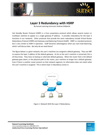
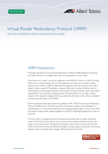
VRRP Configuration ExamplesVRRP Configuration ExamplesThe following examples show how to configure a virtual router in a LAN: "VRRP preferred master with backup configuration" on page 14 "VRRP circuit failover configuration" on page 17 "VRRPv2 to VRRPv3 transition configuration" on page 22 "Virtual Router Redundancy Protocol IPv6 (VRRPv3) configuration" on page 28VRRP preferred master with backup configurationThis example show how to configure a basic virtual router with a preferred master and abackup.InternetVirtual RouterSwitch A(Master)Host 1Switch B(Backup)Host 2Host 3VRRP-2 SSwitch A owns the IP address of the virtual router, and always assumes the role of masterwhenever it is available. Switch B is the backup, and assumes the role of master, backing upthis IP address if A becomes unavailable.Page 14 Virtual Router Redundancy Protocol (VRRP)
VRRP Configuration ExamplesStep 1: Configure Switch AAt this point we assume that you have already created VLAN 2 on Switch A.a.Configure an IP address on VLAN 2awplus#configure terminal Enter the Global Configuration mode.awplus(config)#hostname Switch A Assign the host name Switch A.Switch A(config)#interface vlan2Specify the interface (vlan2) that willparticipate in virtual routing to first configurean IP address for vlan2.Switch A(config-if)#ip address 192.168.1.1/24b.Specify the IP address and mask for interfacevlan2.Create the Master Virtual RouterSwitch A(config)#spanning-tree mode stpConfigure STP for interfaces on Switch A.Switch A(config)#router vrrp 1 vlan2Create a new VRRP session on the router,specify the VRID for the session, and specifythe interface (vlan2) that will participate invirtual routing.Switch A(config-router)#Set the virtual IP address for theVRRP session.virtual-ip 192.168.1.1master Define the default state of the VRRP routerwithin the virtual router.Switch A(config-router)enableEnable the VRRP session on the router.Switch A(config-router)#exitExit the Router Configuration mode and enterthe Global Configuration mode.Switch A(config)#awplusexit# Exit the Global Configuration mode and enterthe Privileged Exec mode.Switch A# Privileged Exec mode prompt.Virtual Router Redundancy Protocol (VRRP) Page 15
VRRP Configuration ExamplesStep 2: Configure Switch BAt this point we assume that you have already created VLAN 2 on Switch B.a.Configure an IP address on VLAN 2awplus#configure terminal Enter Global Configuration mode.awplus(config)#hostname Switch B Assign the host name Switch B.Switch B(config)#interface vlan2Specify the interface (vlan2) that will participate invirtual routing.Switch B(config)#ip address 192.168.1.2/24b.Specify the IP address and mask for interfaceCreate the Backup Virtual RouterSwitch B(config)#router vrrp 1 vlan2Create a new VRRP session on the router, specifythe VRID for the session, and specify the interface(vlan2) that will participate in virtual routing.Switch B(config-router)#Set the virtual IP address for the VRRP session.virtual-ip 192.168.1.1backup Define the default state of the VRRP router withinthe virtual router.Switch B(config-router)#enableEnable the VRRP session on the router.Switch B(config-router)exitExit the Interface Configuration mode and enterthe Global Configuration mode.Switch B(config)#exitReturn to the Privileged Exec mode.Switch B# Privileged Exec mode prompt.Page 16 Virtual Router Redundancy Protocol (VRRP)
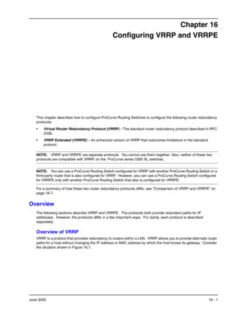
VRRP Configuration ExamplesVRRP circuit failover configurationThis example show how to configure a circuit-failover on a virtual router. This exampleconfigures redundancy between Switch A and Switch B for hosts on VLAN 2 and VLAN 3.The need for VRRP Circuit Failover arose because VRRPv2 was unable to track the gatewayinterface status. The AlliedWare Plus VRRP Circuit Failover feature provides a dynamicfailover of an entire circuit in the event that one of the members of the group fails.This introduces the concept of a circuit, where two or more Virtual Routers on a singlesystem are grouped. In the event of a failure occurring a Virtual Router performs the Masterto Backup transition and notifies the other Virtual Routers. These are then forced into theMaster to Backup transition, so that both incoming and outgoing packets are routed throughthe same gateway router, eliminating the problem for NAT environments.To configure VRRP Circuit Failover, each circuit is configured to have a corresponding prioritydelta value, which is passed to VRRP when a failure occurs. The priority of each VirtualRouter on the circuit is decremented by the priority delta value, which causes the VirtualRouter Master to Virtual Router Backup transition. In this example, two switches Switch Aand Switch B are configured as backup routers with different priorities. The priority deltavalue is configured to be greater that the difference of both the priorities.Host 1Host 2Host 3Switch AVLAN 2goes downSwitch BVLAN 2is link upVirtual RouterSwitch B(Backup)Switch A(Master)VLAN 3Host 4Host 5Host 6VRRP-3 SSwitch A is configured to have a priority of 100, and Switch B is configured to have apriority of 90. Switch A with a greater priority is the Virtual Router Master. The priority deltavalue is 20, greater than 10 (100 minus 90).Virtual Router Redundancy Protocol (VRRP) Page 17
VRRP Configuration ExamplesOn Switch A, when vlan2 fails, the priority of Switch A becomes 80 (100 minus 20). SinceSwitch B has a greater priority (90) than Switch A, Switch B becomes the Virtual RouterMaster, and routing of packets continues without interruption. When this Virtual RouterBackup (Switch A) is up again, it regains its original priority (100), and becomes the VirtualRouter Master again.Step 1: Configure Switch Aa.Configure an IP address on VLAN 2awplus#configure terminal Enter the Global Configuration mode.awplus(config)#hostname Switch A Assign the host name Switch A.Switch A(config)#interface vlan2Specify the interface (vlan2) that willparticipate in virtual routing to first configurean IP address for vlan2.Switch A(config-if)#ip address 192.168.1.1/24b.Specify the IP address and mask for interfacevlan2.Configure an IP address on VLAN 3Switch A(config-if)#exitExit the Interface Configuration mode andenter the Global Configuration mode.Switch A(config)#interface vlan3Specify the interface (vlan3) that willparticipate in virtual routing to first configurean IP address for vlan3.Switch A(config-if)#ip address 192.168.2.1/24c.Specify the IP address and mask for interfacevlan3.Create the Master Virtual RouterSwitch A(config)#router vrrp 1 vlan2Create a new VRRP session on the router,specify theVRID for the session, and specify theinterface (vlan2) that will participate in virtualrouting.Switch A(config-router)#Set the virtual IP address for the VRRP session.virtual-ip 192.168.1.1backup Define the default state of the VRRP routerwithin the virtual router.Switch A(config-router)#priority 100Page 18 Virtual Router Redundancy Protocol (VRRP)Set the VRRP priority to 100 as the defaultpriority for a Backup Virtual Router.
VRRP Configuration ExamplesSwitch A(config-router)#preempt-mode trueSet preempt mode
undesirable to use a dynamic routing protocol. One alternative is to use static routing; however, if the statically configured first hop switch fails, the hosts on the LAN are unable to communicate with those on theWAN. TheVirtual Router Redundancy Protocol is defined in RFC 5798 (Virtual Router Redundancy Protocol (VRRP)Version 3 for IPv4 and .