Transcription
Mechanical Seal Piping PlansSingle Seals plans 01, 02, 03, 11, 13, 14, 21, 23, 31, 32, 41Dual Seals plans 52, 53A, 53B, 53C, 54, 55Quench Seals plans 62, 65A, 65B, 66A, 66BGas Seals plans 72, 74, 75, 76
Mechanical Seal Piping PlansFlowserve recognizes that one of the most effective ways to achieve long,uninterrupted mechanical seal life is to create a healthy environment aroundthe seal faces. Piping plans help keep mechanical seals running cool andclean, promote safe handling of dangerous fluids, and extend the operationalavailability of rotating equipment. This reference book provides a concisesummary of the most essential piping plans used successfully in today’sprocess plants.Each plan shows all the standard and optional auxiliary components referencedin API Standard 682 and recommended by Flowserve. Consult your localFlowserve sales engineer to identify the right solution that satisfies yourapplication requirements.
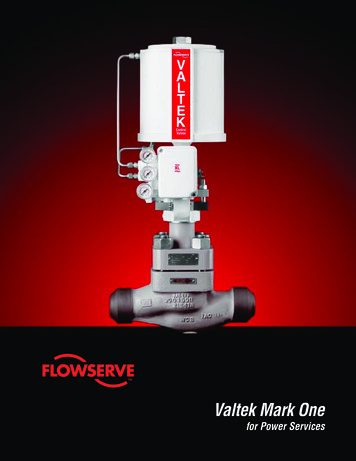
Page LayoutSeal End ViewPiping Plan LayoutWhat, Why, and Where Viewed from drive end Shows preferred glandconnection orientation Illustrated schematicof auxiliary components Describes piping plans,their purpose, andtypical applicationsflowserve.comPlan 53Aoutletpressuretransmittersealend viewinletliquid fill,normally closedreservoirlevel indicatorcooling outleveltransmittercooling coilscooling indrain,normallyclosedWhatPressurized barrier fluid circulation through reservoir.Fluid is circulated by a pumping ring in the dual seal assembly.WhyIsolate process fluid.Zero process emissions.WhereUsed with dual pressurized seals (”double”).High vapor pressure fluids, light hydrocarbons.Hazardous/toxic fluids.Heat transfer fluids.Dirty/abrasive or polymerizing fluids.Mixers/agitators and vacuum service.Plan 53Apressure source,normally openPreventative Maintenance - Reference Appendix BPiping loop must self-vent to reservoir locate at highest elevation.Pressurize reservoir at all times, maximum gas charge 10 - 14 bar (150 - 200 psi).Barrier fluid must be compatible with process.Reservoir level gage indicates both inboard and outboard seal leakage.Pump Cross-sectionMechanical SealPreventative Maintenance Simplified centrifugalpump shown for all plans Shows typical sealarrangements Provides general tips toimprove reliability and fortroubleshooting
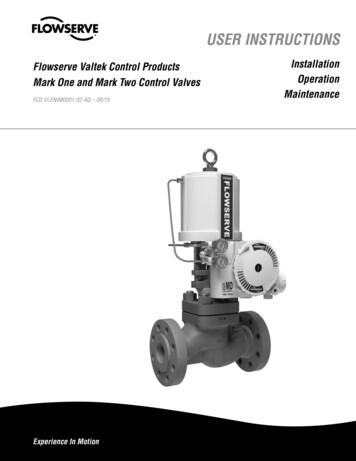
Plan 01sealend viewinternal porting
flowserve.comWhySeal chamber heat removal.Seal chamber venting on horizontal pumps.Reduce risk of freezing/polymerizing fluid in exposed Plan 11 piping.WhereCustom seal chamber, most likely an ANSI/ASME pump.Clean, moderate temperature fluids.Used with single seals, rarely with dual seals.Preventative MaintenanceFlush typically can not be directed over seal faces and seal heat removal is limited.Calculate flush flow rate based on head loss through internal porting.Plan 01WhatInternal seal chamber flush from pump discharge.Operates similar to Plan 11.
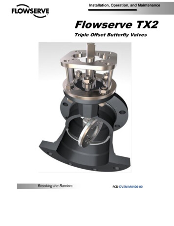
Plan 02sealend view
flowserve.comWhatDead-ended seal chamber with no flush.WhereCooling jacket seal chambers in high temperature services.Clean fluids.Top-entry mixers/agitators with dry seals.Heating jacket seal chambers in fluids that solidify at low temperatures.Preventative MaintenanceProcess must have adequate boiling point margin to avoid vaporization.Cooling fluid in seal chamber jacket may be needed at all times in hot services.Horizontal equipment must be self-venting.Often used in combination with steam quench, Plan 62.Plan 02WhyNo fluid recirculation needed.
Plan 03sealend viewtapered bore seal chamber shown
flowserve.comWhatCirculation created by the design of the seal chamber.WhereLarge bore/open throat seal chambers.Dirty or contaminated fluids.Preventative MaintenanceProper seal chamber design helps prevent solids from collecting at the seal faces.Plan 03WhyNo external fluid recirculation needed.Solids removal from seal chamber.
inletPlan 11sealend vieworifice
flowserve.comWhySeal chamber heat removal.Seal chamber venting on horizontal pumps.Increase seal chamber pressure and fluid vapor margin.WhereGeneral applications with clean fluids.Clean, non-polymerizing fluids.Preventative MaintenanceUse an orifice with a minimum 3 mm (1/8 inch) diameter.Calculate flow rates to size orifice for adequate seal chamber flow.Increase boiling point margin with proper orifice and throat bushing sizing.Flush should be directed over seal faces with piping at 12 O’clock position.Typical failure mode is a clogged orifice - check temperatures at pipe ends.Plan 11WhatSeal flush from pump discharge through orifice.Default single seal flush plan.
outletPlan 13sealend vieworifice
flowserve.comWhyContinuous seal chamber venting on vertical pumps.Seal chamber heat removal.WhereVertical pumps.Seal chamber pressure is greater than suction pressure.Moderate temperature fluids with moderate solids.Non-polymerizing fluids.Preventative MaintenanceVent piping loop prior to starting vertical pumps.Use an orifice with a minimum 3 mm (1/8 inch) diameter.Calculate flow rates to size orifice for adequate seal chamber flow.Reduce seal chamber pressure with proper orifice and throat bushing sizing.Typical failure mode is a clogged orifice - check temperatures at pipe ends.Plan 13WhatRecirculation from seal chamber to pump suction through orifice.Standard flush plan on vertical pumps.
outletPlan 14sealend viewinletorifices
flowserve.comWhyContinuous seal chamber venting on vertical pumps.Seal chamber heat removal.Increase seal chamber pressure and fluid vapor margin.WhereVertical pumps.Clean, non-polymerizing fluids at moderate temperatures.Preventative MaintenanceUse an orifice with a minimum 3 mm (1/8 inch) diameter.Calculate flow rates to size orifice for adequate seal chamber flow.Increase boiling point margin with proper orifice and throat bushing sizing.Flush should be directed over seal faces.Vent piping loop prior to starting vertical pumps.Typical failure mode is a clogged orifice - check temperatures at pipe ends.Plan 14WhatSeal flush from pump discharge and recirculation to pump suction with orifices.Combination of Plan 11 and Plan 13.
vents,normally closedinletcooling outPlan 21sealend viewcoolerorificetemperatureindicatorcooling coilscooling indrain,normallyclosed
flowserve.comWhySeal cooling.Reduce fluid temperature to increase fluid vapor margin.Reduce coking.WhereHigh temperature service, typically less than 177 C (350 F).Hot water over 80 C (180 F).Clean, non-polymerizing fluids.Preventative MaintenanceSeal cooler and piping must have air vents at highest elevation - vent before starting.When using 682 Seal Cooler, pipe with series flow to maximize heat transfer.Use an orifice with a minimum 3 mm (1/8 inch) diameter.Calculate flow rates to size orifice for adequate seal chamber flow.Increase boiling point margin with proper orifice and throat bushing sizing.Regularly monitor cooler inlet and outlet temperatures for signs of clogging or fouling.Plan 21WhatSeal flush from pump discharge through orifice and cooler.Cooler added to Plan 11 flush increases heat removal.
vent, normally closedoutletcooling outPlan 23sealend viewinletcoolertemperatureindicatorcooling coilscooling indrain,normallyclosed
flowserve.comWhyEfficient seal cooling with low cooler duty.Increase fluid vapor margin.Improve water lubricity.WhereHigh temperature service, hot hydrocarbons.Boiler feed water and hot water over 80 C (180 F).Clean, non-polymerizing fluids.Preventative Maintenance - Reference Appendix ASeal cooler and piping must have air vents at highest elevation - vent before starting.When using 682 Seal Cooler, pipe with parallel flow to minimize head loss.Seal chamber requires close clearance throat bushing to isolate process fluid.Tangential seal gland taps should enter at bottom and exit at top.Regularly monitor cooler inlet and outlet temperatures for signs of clogging or fouling.Process fluids with iron should flow through magnetic separator before cooler.Plan 23WhatSeal flush from internal pumping device through cooler.Standard flush plan in hot water services.
inletPlan 31sealend viewcyclone separator
flowserve.comWhySeal chamber heat removal.Solids removal from flush and seal chamber.WhereDirty or contaminated fluids, water with sand or pipe slag.Non-polymerizing fluids.Preventative MaintenanceCyclone separator works best on solids with a specific gravity twice the process fluid.Seal chamber pressure must be nearly equal to suction pressure for proper flows.Piping should not include an orifice and is not expected to vent the seal chamber.Typical failure mode is clogged separator or pipes - check temperatures at pipe ends.Plan 31WhatSeal flush from pump discharge through cyclone separator.Centrifuged solids are returned to pump suction.
inletPlan 32sealend )flow controlvalveflowindicator(optional)check valvestrainerfrom clean source,normally open
flowserve.comWhySeal chamber heat removal.Process and solids removal from seal chamber.Increase seal chamber pressure and fluid vapor margin.WhereDirty or contaminated fluids, paper pulp.High temperature service.Polymerizing and/or oxidizing fluids.Preventative MaintenanceUse throat bushing sized to hold pressure or maintain flow velocity.To restrict dirty process fluid, regulate injection flow rate.To increase fluid vapor margin, regulate injection pressure.Injection fluid must be compatible with process fluid.Regularly monitor control system for closed valves or signs of plugging.Plan 32WhatSeal flush from an external clean source.
vents,normally closedinletcooling outPlan 41sealend ing coilscooling indrain,normallyclosed
flowserve.comWhySeal cooling.Solids removal from flush and seal chamber.WhereHigh temperature service, typically less than 177 C (350 F).Dirty or contaminated fluids, water with sand or pipe slag.Non-polymerizing fluids.Preventative MaintenanceSeal cooler and piping must have air vents at highest elevation - vent before starting.When using 682 Seal Cooler, pipe with series flow to maximize heat transfer.Cyclone separator works best on solids with a specific gravity twice the process fluid.Seal chamber pressure must be nearly equal to suction pressure for proper flows.Typical failure mode is clogged separator or pipes - check temperatures at pipe ends.Plan 41WhatSeal flush from pump discharge through cyclone separator and cooler.Combination of Plan 21 and Plan 31.
vent,normally openoutletPlan 52sealend viewinletorificeliquid fill,normally cooling coilscooling outcooling indrain,normallyclosed
flowserve.comWhyOutboard seal acts as a safety backup to the primary seal.Zero to very low process emissions.No process contamination is allowed.WhereUsed with dual unpressurized seals.High vapor pressure fluids, light hydrocarbons.Hazardous/toxic fluids.Heat transfer fluids.Preventative Maintenance - Reference Appendix BPiping loop must self-vent to vapor recovery/flare system near atmospheric pressure.Process vapor pressure is generally greater than reservoir pressure.Buffer fluid must be compatible with process leakage.Primary seal leakage is indicated by increased vent pressure.Reservoir level indicator shows outboard seal leakage.Plan 52WhatUnpressurized buffer fluid circulation through reservoir.Fluid is circulated by a pumping ring in the dual seal assembly.
pressure source,normally openoutletPlan 53Asealend viewinletpressuretransmitterorificeliquid fill,normally closedreservoirleveltransmitterlevel indicatorcooling coilscooling incooling outdrain,normallyclosed
flowserve.comWhyIsolate process fluid.Zero process emissions.WhereUsed with dual pressurized seals.High vapor pressure fluids, light hydrocarbons.Hazardous/toxic fluids.Heat transfer fluids.Dirty/abrasive or polymerizing fluids.Mixers/agitators and vacuum service.Preventative Maintenance - Reference Appendix BPiping loop must self-vent to reservoir located at highest elevation.Pressurize reservoir at all times, maximum gas charge 10 - 14 bar (150 - 200 psi).Barrier fluid must be compatible with process.Reservoir level indicator shows both inboard and outboard seal leakage.Plan 53AWhatPressurized barrier fluid circulation through reservoir.Fluid is circulated by a pumping ring in the dual seal assembly.
Plan 53Boutletsealend viewinletvent,normally closedpressuretransmitterpressure source,normally closedtemperaturetransmitterfinned atureindicatorliquid fill,normally closeddrain,normallyclosed
flowserve.comWhyIsolate process fluid.Zero process emissions.Higher pressure than Plan 53A.WhereUsed with dual pressurized seals.High vapor pressure fluids, light hydrocarbons.Hazardous/toxic fluids.Heat transfer fluids.Dirty/abrasive or polymerizing fluids.Preventative Maintenance - Reference Appendix BPiping loop must be fully vented before starting.Accumulator must be pressurized at all times, usually by gas charge.Barrier fluid must be compatible with process.Regularly monitor barrier pressure - manually add barrier fluid when pressure decays.Plan 53BWhatPressurized barrier fluid circulation with bladder accumulator.Fluid is circulated by a pumping ring in the dual seal assembly.
level indicatorPlan 53Coutletlevel transmittervent, normally closeddifferential pressuretransmittersealend viewinletcoolerliquid fill,normallyclosedpistonaccumulatordrain, normally closedtemperatureindicator(optional)
flowserve.comWhyIsolate process fluid.Zero process emissions.Higher pressure than Plan 53A.Dynamic tracking of system pressure.WhereUsed with dual pressurized seals.High vapor pressure fluids, light hydrocarbons.Hazardous/toxic fluids.Heat transfer fluids.Preventative Maintenance - Reference Appendix BPiping loop must be fully vented before starting.Reference line must tole
Seal flush from pump discharge through cyclone separator. Centrifuged solids are returned to pump suction. Why Seal chamber heat removal. Solids removal from flush and seal chamber. Where Dirty or contaminated fluids, water with sand or pipe slag. Non-polymerizing fluids. Preventative MaintenanceFile Size: 1MBPage Count: 66