Transcription
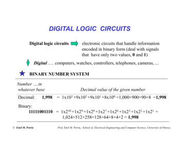
DIGITAL LOGIC CIRCUITSDigital logic circuitselectronic circuits that handle informationencoded in binary form (deal with signalsthat have only two values, 0 and 1)Digital . computers, watches, controllers, telephones, cameras, .BINARY NUMBER SYSTEMNumber .inwhatever baseDecimal value of the given numberDecimal:1,998 1x10³ 9x10² 9x101 8x100 1,000 900 90 8 1,998Binary:11111001110 1x210 1x29 1x28 1x27 1x26 1x23 1x22 1x21 1,024 512 258 128 64 8 4 2 1,998 Emil M. PetriuProf. Emil M. Petriu, School of Electrical Engineering and Computer Science, University of Ottawa
Powers of 2,048“Kilo”as 210 is the closest power of 2 to 1,000 (decimal) .1532,768215 Hz often used as clock crystal frequency in digital watches .201,048,576“Mega” as 220 is the closest power of 2 to 1,000,000 (decimal) .301,073,741,824“Giga” as 230 is the closest power of 2 to 1,000,000,000(decimal) Emil M. Petriu
Negative Powers of 2N 02N-1-2-3-4-5-6-7-8-9-10 2-1 0.52-2 0.252-3 0.1252-4 0.06252-5 0.031252-6 0.0156252-7 0.00781252-8 0.003906252-9 0.0019531252-10 0.0009765625 Emil M. PetriuBinary numbers less than 1BinaryDecimal ------------------0.101101 1x2-1 1x2-3 1x2-4 1x2-6 0.703125
-----------Binary Decimal -----------------------------111 1100 111071214 DecimalHexadecimal: 7CE 7x162 12x161 14x160 ------ Emil M. Petriu
LOGIC OPERATIONS AND TRUTH TABLESDigital logic circuits handle data encoded in binary form, i.e. signalsthat have only two values, 0 and 1.Binary logic dealing with “true” and “false” comes in handy to describethe behaviour of these circuits: 0 is usually associated with “false” and1 with “true.”Quite complex digital logic circuits (e.g. entire computers) can be builtusing a few types of basic circuits called gates, each performing a singleelementary logic operation : NOT, AND, OR, NAND, NOR, etc.Boole’s binary algebra is used as a formal / mathematical tool todescribe and design complex binary logic circuits. Emil M. Petriu
GATESAANOTA10AANDA.B001101BF A01010001ABABORA B001101010111 Emil M. PetriuAF A BBF A . B
more GATESABNANDA.B001101011110AF A . BBABNORA B001101011000 Emil M. PetriuAF A BB
and more GATESABXORA B001101010110AF A BBABEQU or XNORA B001101011001 Emil M. PetriuAF A BB
EXAMPLES OFGATES WITHTHREE INPUTSGATES with more inputsABC A. B.C A B C A.B.CA B 0000000ABCABCANDORF A.B.CF A B CABC Emil M. PetriuNANDF A.B.CABCNORF A B C
Logic Gate Array that Produces an Arbitrarily Chosen OutputAABCBCF A.B .C A.B .C A.B .C A.B .CF00001111001100110101010100110101A.B .CA.B .CFA.B .CA.B .CA Emil M. PetriuBACBC“Sum-of-products”form of the logic circuit.
BOOLEAN ALGEBRA“ Proof ”:AND rulesA.A AA B C A. (B C) A.B A.CA.A 00 .A 01.A AA.B B.AA . (B . C) (A . B) . CA . (B C) A . B A . CA.B A B Emil M. Petriu0000111100110011010101010000011100000111
BOOLEAN ALGEBRA continuedOR rulesA B C A B.C (A B) . (A C)A A AA A 10 A A1 A 1A B B AA (B C) (A B) CA B . C (A B) . (A C)A B A. B Emil M. Petriu0000111100110011010101010001111100011111
DeMorgan’s TheoremA B A.B A B A B A.BA.B A BA B A. B Emil M. Petriu001101011000100011101110
Simplifying logic functions using Boolean algebra rulesABCSum-of-products form of the logic function:F ABC ABC ABC ABCA.B .CA.B .CFA.B .CA.B .CABACBC Emil M. Petriu
Simplifying logic functions using Boolean algebra rules continuedF ABC ABC ABC ABCF (ABC ABC) (ABC ABC)F A(BC BC) A ( BC BC)F AB( C C) AC ( B B)AB1C1F AB ACA.BFA.CAA Emil M. Petriu
Simplifying logic functions using Karnaugh mapsKarnaugh map graphical representationof a truth table for a logic function.Each line in the truth table correspondsto a square in the Karnaugh map.The Karnaugh map squares are labeled sothat horizontally or vertically adjacent squaresdiffer only in one variable. (Each square inthe top row is considered to be adjacent to acorresponding square in the bottom row. Eachsquare in the left most column is considered tobe adjacent to a corresponding square in theright most column.)Karnaugh map Emil M. Petriu(0)(1)(2)(3)(4)(5)(6)(7)A B CF00001111.0011001101010101AB00 01 11 10C0026411375
Simplifying logic functions of 4 variables using Karnaugh mapsA B 011D F0101010101010101. .AB00 01 11 10CD00 0 4 12 80115139113715 11102614 10 Emil M. Petriu
Simplifying logic functions using Karnaugh maps loopingThe logic expressions for an output can be simplified by properlycombining squares (looping) in the Karnaugh maps which contain 1s.Looping a pair of adjacent 1s eliminates the variable that appears inboth direct and complemented form.(0)(1)(2)(3)(4)(5)(6)(7) Emil M. PetriuA B C FAB00001111C00110011010101010011010100 01 11 100 01001 0111ABACF AB AC
Simplifying logic functions using Karnaugh maps more loopingA B 011Looping a quad of adjacent 1s eliminatesthe two variables that appears inboth direct and complemented form.D F01010101010101011010010100001111AB00 01 11 10CD00 1 0 1001 0 1 101101 10101001ABDABBDF A B D AB BD Emil M. Petriu
DeMorgan’sTheoremEquivalent Gate Symbols A BABA B A. BABA.BAA.B A B A BBABA. B Emil M. Petriu
NAND gate implementation of the “sum-of-product” logic functionsNAND gates are faster than ANDs andORs in most technologiesF AB ACABCX (X)A BCFAAFA Emil M. Petriu
ADDING BINARY NUMBERSAdding two bits:0 00 11 01 1011Truth tableInputsA B00110101OutputsCarry Sum00010110Sum A BCarry(over)The binarynumber 10 isequivalent tothe decimal 210SumASumBHalf-AddercircuitCarryCarry A . B Emil M. Petriu
Adding multi-bit numbers:11 000 110Sum01 111 000CarryS7 S6 S5 S4 S3 S2 S1 S0A7 B7A6 B6A5 B5A4 B4A3 B3A2 B2A1 B1A0 B0A BA BA BA BA BA BA BA BCO CICO CICO CICO CICO CICO CICO CICO CISSSSSSSSS7S6S5S4S3S2S1S0Carry In 0Carry OutA7 A6 A5 A4 A3 A2 A1 A0 B7 B6 B5 B4 B3 B2 B1 B00 1 1 0 1 1 00 0 1 0 1 1 0 10108D 90D198D Emil M. Petriu
Full AdderA BCO CISSumCarry InCarry OutBits of the samerank of the twonumbersInputsA B CI000011110011001101010101OutputsCO S0001011101101001ABCIS00 01 11 100 01011 1010COABCIA .B00 01 11 100 00101 0111B. CIA . CIS A . B . CI A . B . CI A . B . CI A . B . CIC A . B B . CI A . CI Emil M. Petriu
HEX-TO-7 SEGMENT DECODERThis examples illustrates how a practical problem is analyzed in order to generatetruth tables,and then how truth table-defined functions are mapped on Karnaugh maps.B3 B2 B1 f the hexdigits“Natural” (i.e.as humans write)representation of the “hex” digits.7-segment display to allowthe user see the naturalrepresentation of thehex digits.S1S6S5S7 S6S5S7S4S4S2S3S3 S27 SEGMENTHEXB3B2 B1B0S1Binary outputs; whensuch a signal is 1 thenthe corresponding segmentin the 7-segment displayis on (you see it), when thesignal is 0 then thesegment is off (you can’tsee it).The four-bit representationof the hex digits Emil M. Petriu
S1B3 B2 B1 S5S2S3S5S7S4S5S6S5S2S3S6S5S7S4We are developing ad-hoc”binary-hex logic” expressions usedjust for our convenience in the problem analysis process. Eachexpression will enumerate only those hex digits when thespecific display-segment is “on”:S1 0 2 3 5 6 7 8 9 A C E FS2 0 1 2 3 4 7 8 9 A 7S1S7S4S6S7S4S6S5S2S7S4S3S1S2S3S6S5S7S4S2S3S1S3 0 1 3 4 5 6 7 8 9 A B DS4 0 2 3 5 6 8 9 B C D ES5 0 2 6 8 A B C D E FS6 0 4 5 6 8 9 A B C E FS7 2 3 4 5 6 8 9 A B D E FS6S5S7S4S2S3 Emil M. Petriu
Hex-to-7 segmentB3 B2 B1 01010101010101S1 0 2 3 5 6 7 8 9 A C E FS2 0 1 2 3 4 7 8 9 A DS3 0 1 3 4 5 6 7 8 9 A B DS4 0 2 3 5 6 8 9 B C D EB3 B2B1 B000 01 11 10S5 0 2 6 8 A B C D E F00 04C 8S6 0 4 5 6 8 9 A B C E F0115 D 9S7 2 3 4 5 6 8 9 A B D E F1137 F1026 E ABAs we are using ad-hoc “binary-hex logic”equations, (i.e. binary S outputs as functionsof hex variables) it will useful in this case to havehex-labeled Karnaugh map, instead of the usual 2-D(i.e. two dimensional) binary labeled K maps. Thiswill allow for a more convenient mapping of the“binary-hex” logic equations onto the K-maps. Emil M. Petriu
Hex-to-7 segmentB3 B2Mapping the ad-hoc “binary-hexlogic” equations onto Karnaugh maps:B1 B0B3 B2B1 B000 01 11 1000 0 4S1B3 B200 01 11 10B1 B0S200 01 11 1000101100110101010101101111111 011110 010111 110100 1C 8011 5 D 9113 7 F102 6 E AB3 B2BB1 B0S1 0 2 3 5 6 7 8 9 A C E FS2 0 1 2 3 4 7 8 9 A DS3 0 1 3 4 5 6 7 8 9 A B DS3B3 B200 01 11 10B1 B0S400 01 11 1000110100101101111101011111110 111100 110010 110111 0S4 0 2 3 5 6 8 9 B C D E Emil M. Petriu
Hex-to-7 segmentB3 B2B1 B0B3 B2S5B3 B2B1 B000 01 11 10S600 01 11 10001011001111010010010101C 811001 111001 1011 5 D 910111 110011 1113 7 F102 6 E AB1 B000 01 11 1000 0 4BB3 B2B1 B0S5 0 2 6 8 A B C D E FS6 0 4 5 6 8 9 A B C E FS7 2 3 4 5 6 8 9 A B D E FS700 01 11 1000010101011111101 110111 1 Emil M. Petriu
SYSTEMS of LOGIC FUNCTIONS2- bit ComparatorA1 A0 B1 B0 F1 F2 4)(15)0 0 0 00 0 0 10 0 1 00 0 1 10 1 0 00 1 0 10 1 1 00 1 1 11 0 0 01 0 0 11 0 1 01 0 1 11 1 0 01 1 0 11 1 1 01 1 1 ompare two 2-bit numbers:A BF1 Σ (0,5,10,15)A BF2 Σ (4,8,9,12,13,14)A BF3 Σ (1,2,3,6,7,11) Emil M. Petriu
2- bit ComparatorA BF1 Σ (0,5,10,15)A1A0B1B0A1 A0B1 B000 01 11 1000 01 11 1000 1 0 001 0 1 00000 0412811001001 151391000013715 1110 2614 1011F1 1 when both numbers, A and B,are equal which happens when alltheir bits of the same order are identical,i.e. A0 B0 AND A1 B1F1 (A0 B0) (A1 B1) Emil M. Petriu
2- bit ComparatorA BF3 Σ (1,2,3,6,7,11)A1 A0B1 B000 01 11 1000 0412801 151393715 1110 2614 1011A1A0B1B0 00 01 11 1000 0 0 0 001 1 0 0 0111101101100F3 A0B1B0 A1B1 A1A0B0 Emil M. Petriu
2- bit ComparatorA BA1 A0F2 Σ (4,8,9,12,13,14)B1 B0A1A0B1B000 01 11 1000 001 011101111 000010 0010F1 F3A1A0 Emil M. Petriu11111110110100 041280115139113715 11102614 10F2 F1 F3F1A1A0B1B0 00 01 11 1000 1 0 0001 1 1 0 000 01 11 10B1B0F3A1A000 01 11 10B1B0 00 01 11 1000 0 0 0001 1 0 0 000 1000010100110010111101100001101100
2- bit ComparatorF1 (A0 B0) (A1 B1)F2 F1 F3B1 B0 A1 A0F3 A0B1B0 A1B1 A1A0B0A1 B1F1 (A0 B0) (A1 B1)A0 B0F2 F1 F3F3 A0B1B0 A1B1 A1A0B0 Emil M. Petriu
ABC3-to-8 DecoderF0A B C F0 F1 F2 F3 F4 F5 F6 00001000000001F1F2F3F4F5F6F7 Emil M. Petriu
3-to-8 Decoder (74 138)EABCF0A B C E F0 F1 F2 F3 F4 F5 F6 0101011 10 00 10 10 10 10 111111101111111110F1F2F3F4F5F6F7 Emil M. Petriu
BCD-TO-7 SEGMENT DECODERS1B3 B2 B1 B0S6S5S7 S6S5S7S4S4S2S3S3 S27 SEGMENTBCDB3 Emil M. PetriuB2 110101010101010101B3 B2B1 B000 01 11 1000 04x80115x91137xx1026xx“Don’t Care” states/situations.As it is expected that thesestates are never going to occur,then we may just as well usethem as fill-in “1s” in aKarnaugh map if this helps tomake larger loopings
BCD-to-7 segmentS1B3 B2 B1 11110000111100001111 Emil M. S5S1S2S3S6S5S7S4S4S3S1S2S3S6S5S7S4S4 0 2 3 5 6 8 9S1 0 2 3 5 6 7 8 9S5 0 2 6 8S2 0 1 2 3 4 7 8 9S6 0 4 5 6 8 9S3 0 1 3 4 5 6 7 8 9S7 2 3 4 5 6 8 9S2S3
B3 B2BCD-to-7 segmentB1 B0S1 0 2 3 5 6 7 8 9B3 B2B1 B000S100 01 11 1010x10101x11111x x1011x x00 01 11 1000 04x80115x91137xx1026xxS2 0 1 2 3 4 7 8 9S2B3 B200 01 11 10B1 B000 1 1 x 10110x1111x x1010x x1S1 B3 B2B0 B1 B2B1 B2B0S2 B3 B2 B1B0 B1B0 Emil M. Petriu
BCD-to-7 segmentB3 B2B1 B0S3 0 1 3 4 5 6 7 8 9S3B3 B200 01 11 10B1 B000 1 1 x 100 04x80115x9113 7xx102 6xxS4 0 2 3 5 6 8 9B3 B2B1 B0S400 01 11 100010x10111x10101x11111x x1110xx1001x x1011xxS3 B3 B1B0 B1 B2 Emil M. Petriu00 01 11 10S4 B3 B2B0 B2B1 B2B1B0 B1B0
B3 B2B1 B000 01 11 1000 04x815x90111310 276xxB1 B000S7 2 3 4 5 6 8 9S6 0 4 5 6 8 9B3 B2B1 B0S60x100 11x10100x001 01x11100x x1100x x1011x x10 01x xB2B0 B1B00001x10101x11110xx1011xx00 01 11 101S5 00 01 11 10B1 B0xS500 01 11 10S7B3 B2xS5 0 2 6 8B3 B2BCD-to-7 segmentS7 B3 B2B1 B1B2 B1B0S6 B3 B1B0 B1B2 B2B0 Emil M. Petriu
I1 I2 FMEMORY ELEMENTS:LATCHES AND FLIP-FLOPSR-S LatchS 0(Reset-Set)SI1FI2001101011110Q 1S 0Q 1R 1Q 0QR 0Q 1QRS 1S RQ Q00111 11 00 1Q Q0101 Emil M. PetriuQ 0S 1Q 1R 1Q 0Weird stateSet stateReset stateHold stateR 0Q 1
D (Transparent) LatchSDQEnable D Q QQR0xQ Q11010 11 0EnableEnable D S RQ Q001 1Q Q011 1Q Q1 01 11 00 10 11 0 Emil M. PetriuS RQ Q00111 11 00 1Q Q0101When the Enable inputis 1 (i.e. TRUE or HIGH)the information present atthe D input is stored in thelatch and will “appear as it is”at the Q output ( it is likethat there is a “transparent”path from the D input to theQ output)
D LatchSDEnable D S RQQREnableQ Q001 1Q Q011 1Q Q1 01 11 00 10 11 rent” state“Hold”state Emil M. Petriu
Latch 1DDEnab.CLKEN1DDin*Synchronous D Flip-FlopLatch 2QQD1DEnab.QQQQPositive-Edge-TriggeredD Flip-FlopDCLKLatch 1 isTransparentD1EN21Input data D may change0101Latch 1 is HoldingQLatch 1 is TransparentChanged input data D enter Latch 1D1 Din*Latch 2 is HoldingLatch 2 is TransparentLatch 2 is HoldingQ D1 Din*The state of the flip-flop’s output Q copies inputD when the positive edge of the clock CLK occurs Emil M. PetriuQEN2CLKEN1Q0101010Positive-Edge-TriggeredD Flip-Flop
Synchronous D Flip-FlopVcc CLR21413D2CLK2 PR2121110Q2Q298Connection diagramof the 7474 DualPositive-Edge-TriggeredD Flip-Flops with Presetand Clear.12CLR1 D134CLK1 PR156Q1Q17GND
COUNTERS4-Bit Synchronous Counter using D Flip-FlopsQ3Q2Q1Q0021345CL4-Bit BINARY COUNTERCK156147CL133Q Σ Qi 2i.12111098i 01CK01CLQ00 12 3 4 5 67 89 10 11 12 13 14 15 012 3 4 56 Emil M. Petriu
DECIMALSTATEBINARY STATE OFTHE 1000001111000011110D3Q3 01111111100001111000011110D1 D00110011001100110D2Q3 Q200 01 11 10Q1 Q0Using D flip-flops has the distinct advantageof a straightforward definition of the flip-flopinputs: the current state of these inputs isthe next state of the counter. The logicequations for all four flip-flop inputs D3, D2,D1, and D0 arederived from thistruth table asQ3 Q2functions of the00 01 11 10Q1 Q0current states of thecounter’s flip-flops:0 4 12 800Q3, Q2, Q1, and Q0.1 5 13 901Karnaugh maps can113 7 15 11be used to simplifythese equations.2 6 14 10101010101010101010D1Q3 Q200 01 11 10Q1 Q0Synchronous 4-bit CounterFLIP FLOP INPUTS(for the next state)00 01 11 10Q1 Q0D0Q3 Q200 01 11 10Q1 110101111001110000110000100011100110101111101111 Emil M. Petriu
Synchronous 4-bit CounterD3Q3 Q200 01 11 10Q1 Q0D2Q3 Q200 01 11 10Q1 D3 Q3. Q2 Q3. Q1 Q3.Q0 Q3.Q2.Q1.Q0D1Q3 Q2D2 Q2. Q0 Q2. Q1 Q2. Q1. Q0Q1 Q000 01 11 10Q1 Q000D0Q3 Q200 01 11 100000011111110000101111D1 Q1. Q0 Q1. Q0001111010000110000101111D0 Q0 Emil M. Petriu
Synchronous 4-bit CounterCLCKQ0DQCLKRQQ0D0 Q0Q1DD1 Q1. Q0 Q1. Q0QCLKD2 Q2.Q0 Q2.Q1 Q2. Q1. Q0RQQ1D3 Q3. Q2 Q3. Q1 Q3.Q0Q2 Q3.Q2.Q1.Q0DQCLKRQQ2Q3DQCLKR Emil M. PetriuQQ3
LOGIC OPERATIONS AND TRUTH TABLES Digital logic circuits handle data encoded in binary form, i.e. signals that have only two values, 0and 1. Binary logicd