Transcription
VLT 6000 HVACIntroduction to HVACIntroductionHVACIntroduction toHVAC ContentsInstallationSoftware version . 3Safety regulations . 4Warning against unintended start . 4Introduction to the Design Guide . 5Available literature . 7Why use a frequency converter for controlling . 8fans and pumps? . 8The clear advantage - energy savings . 8Example with varying flow over 1 year . 9Control principle . 12PC software and serial communication . 15CE-labelling . 16Application examples . 17Specification text . 24Ordering guide . 30Choice of frequency converter . 30Unpacking and ordering a VLT frequency converter . 34Type code ordering number string . 34Ordering form VLT 6000 HVAC . 35InstallationMG.60.B1.02 - VLT is a registered Danfoss trademarkAll aboutVLT 6000 HVACProgrammingGeneral technical data . 42Mains supply 3 x 200 - 240 V . 45Technical data, mains supply 3 x 380 - 460 V . 46Mechanical dimensions . 48Mechanical installation . 50Enclosure protection . 50Field-mounting . 50General information about electrical installation . 52High voltage warning . 52Earthing . 52Cables . 52Screened/armoured cables . 52Extra protection . 52RFI switch . 53High voltage test . 53Heat emission from VLT 6000 HVAC . 53EMC-correct electrical installation . 54Use of EMC-correct cables . 55Earthing of screened/armoured control cables . 56VLT 6000 HVAC enclosures . 57Tightening-up torque and screw sizes . 62Mains connection . 62Pre-fuses . 62Motor connection . 62DC bus connection . 64High-voltage relay . 64Electrical installation, control cables . 65Connection example, VLT 6000 HVAC . 66Switches 1-4 . 671
VLT 6000 HVACProgrammingControl unit LCP . 69Quick menu . 74The Setup configuration . 75Setup of user-defined readout . 76Load and Motor 100-117 . 81Configuration . 81References & Limits 200 - 228 . 88Reference handling . 89Inputs and outputs 300-328 . 97Analogue inputs . 100Analogue/digital outputs . 103Relay outputs . 106Application functions 400-427 . 108Sleep mode . 109PID for process control . 113PID overview . 115Serial communication for FC protocol . 121Protocols . 121Telegram communication . 121Telegram build-up under FC protocol . 122Data character (byte) . 123Process word . 127Control word as per FC protocol . 127Status word as per FC protocol . 129Serial communication 500 - 556 . 132Warning words 1 2 and Alarm word . 140Service functions 600-631 . 142All about VLT 6000 HVACVLTHVACStatus messages . 148List of warnings and alarms . 150Aggressive environments . 156Calculation of resulting reference . 156Extreme running conditions . 158Peak voltage on motor . 159Derating for ambient temperature . 160Efficiency . 162Definitions . 167Factory settings . 169Index . 1752MG.60.B1.02 - VLT is a registered Danfoss trademark
Introduction toHVACVLT 6000 HVACVLT 6000 HVACDesign GuideSoftware version: 1.0xThis Design Guide can be used with all VLT 6000 HVAC frequency converters that have software version 1.0x.See software version number in parameter 624 Software version no.MG.60.B1.02 - VLT is a registered Danfoss trademark3
VLT 6000 HVACThe voltage of the frequency converteris dangerous whenever the equipmentis connected to mains. Incorrect installation of the motor or the frequency converter maycause damage to the equipment, serious personalinjury or death.Consequently, the instructions in this manual, aswell as national and local rules and safetyregulations, must be complied with. Safety regulations1. The VLT frequency converter must be disconnected from mains if repair work is to be carriedout.Check that the mains supply has beendisconnected and that the necessary time haspassed before removing motor and mains plugs.2. The [OFF/STOP] key on the control panel of theVLT frequency converter does not disconnect theequipment from mains and is thus not to be usedas a safety switch.3. Correct protective earthing of the equipment mustbe established, the user must be protectedagainst supply voltage, and the motor must beprotected against overload in accordance withapplicable national and local regulations.4. The earth leakage currents are higher than 3.5 mA.5. Protection against motor overload is not includedin the factory setting. If this function is required,set parameter 117, Motor thermal protection, todata value ETR trip or data value ETR warning.Note: The function is initialised at 1.0 x ratedmotor current and rated motor frequency (seepage 87).For the North American market: The ETRfunctions ensure overload protection of the motor,Class 20, in accordance with NEC.6. Do not remove the plugs for the motor and mainssupply while the VLT frequency converter isconnected to mains. Check that the mains supplyhas been disconnected and that the necessarytime has passed before removing motor andmains plugs.7. Reliable galvanic isolation (PELV) is not compliedwith if the RFI switch is placed in OFF position.This means that all control in- and outputs can nolonger be considered low-voltage terminals.8. Please note that the VLT frequency converter hasmore voltage inputs than L1, L2, L3 when the DCbus terminals are used.Check that all voltage inputs have beendisconnected and that the necessary time haspassed before repair work is commenced. Warning against unintended start1. The motor can be brought to a stop by means ofdigital commands, bus commands, references or alocal stop, while the frequency converter isconnected to mains.If personal safety considerations make itnecessary to ensure that no unintended startoccurs, these stop functions are not sufficient.2. While parameters are being changed, the motormay start. Consequently, the stop key [OFF/STOP] must always be activated, following whichdata can be modified.3. A stopped motor may start if a fault occurs in theelectronics of the VLT frequency converter, or if atemporary overload or a fault in the supply mainsor the motor connection ceases.Warning:Touching the electrical parts may be fatal - even after theequipment has been disconnected from mains.Using VLT 6001-6005: wait at least 4 minutesUsing VLT 6006-6275: wait at least 15 minutes4MG.60.B1.02 - VLT is a registered Danfoss trademark
VLT 6000 HVACThis Design Guide is a tool intended to facilitate the sizing of systems in which VLT 6000 HVAC frequencyconverters are used.HVAC stands for Heating Ventilation Air-Conditioning.This Design Guide progresses step-by-step through the different procedures required for selecting, installing andprogramming a VLT 6000 HVAC.The Design Guide forms part of the literature concept supplied with VLT 6000 HVAC. However, the Design Guideis the most comprehensive document available.When a VLT 6000 HVAC is supplied, it is accompanied by Operating Instructions and a Quick Setup Guide. Seenext page Other literature.Operating Instructions:Describe how to ensure optimum mechanical and electrical installation, andalso deal with commissioning and service. The Operating Instructionsfurthermore provide a description of the software parameters, therebyensuring that you can easily fit the VLT 6000 HVAC into your application.Quick Setup Guide:Helps you get your VLT 6000 HVAC installed and commissioned quickly.Design Guide:Used when designing systems with VLT 6000 HVAC. The Design Guide givesall useful information about the VLT 6000 HVAC and HVAC systems. There isa selection tool for you to choose the right VLT 6000 HVAC with the relevantoptions and modules. The Design Guide has examples of the most commontypes of HVAC applications. In addition, the Design Guide has all informationrelating to Serial Communication.This Design Guide is split in four sections that have information about VLT 6000 HVAC.Introduction to HVAC:This section tells you the advantages that can be obtained by usingfrequency converters in HVAC systems. Furthermore, you can read about theway a frequency converter operates and about the advantages of the VLT6000 HVAC, such as AEO - Automatic Energy Optimisation, RFI filter andother HVAC-relevant functions.There are also examples of applications and information is given aboutDanfoss and CE-labelling.The specification section deals with the requirements relating to beingallowed to supply and install frequency converters. This section can be usedin contract documents, whereby the total list of requirements relating tofrequency converters is determined.The section ends with an Ordering Guide that makes it easier for you tospecify and order a VLT 6000 HVAC.MG.60.B1.02 - VLT is a registered Danfoss trademark5Introduction toHVAC Introduction to the Design Guide
VLT 6000 HVAC Introduction to the Design GuideInstallation:This section shows you how to carry out correct mechanical installation of aVLT 6000 HVAC.In addition, the section has a description of how you ensure that theinstallation of the VLT 6000 HVAC is EMC-correct. Furthermore, the sectionincludes a list of mains and motor connections, as well as a description ofcontrol card terminals.Programming:This section describes the control unit and the software parameters for theVLT 6000 HVAC. There is also a guide to the Quick Setup menu, whichmeans that you will be able to start using your application very quickly.All about VLT 6000:VLTThis section has information about status, warning and fault indications fromthe VLT 6000 HVAC. In addition, the section has technical data, serviceinformation, factory settings and information on special conditions.This symbol indicates somethingto be noted by the reader.6This symbol indicates a general This symbol indicates a highwarning.voltage warning.MG.60.B1.02 - VLT is a registered Danfoss trademark
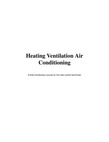
VLT 6000 HVACComeswithVLT MG.60.CX.YYX YY 01 02 03 04 05 06 07 10 20 28 51,52 Other literaturefor VLT 6000HVACDesignGuideMG.60.BX.YYVLT 6000 HVACData sheetMD.60.AX.YYversion numberlanguage ishDutchFinnishBrazilian-PortugueseDanish, English, GermanMG.60.B1.02 - VLT is a registered Danfoss trademarkInstructionsfor VLT6000 HVACCommunicationwith VLT 6000HVACLCP Remotecontrol I.56.DX.51PROFIBUSManualMG.10.EX.YYIP 20 Relay cardinstructionsMI.66.BX.YYIntroduction toHVAC Available literatureThe chart below gives an overview of the literature available for the VLT 6000 HVAC.Please note that variations may occur from one country to the nextMetasys N2LonWorksManualLandis/StaefaFLN7
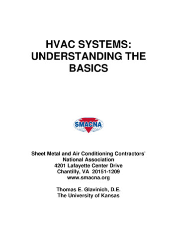
VLT 6000 HVAC Why use a frequency converter for controllingfans and pumps?A frequency converter takes advantage of the fact thatcentrifugal fans and pumps follow the laws ofproportionality for such fans and pumps. The clear advantage - energy savingsThe very clear advantage of using a frequency converter for controlling the speed of fans or pumps lies inthe electricity savings to be obtained.When comparing with alternative regulating systemsand technologies, a frequency converter is the optimum energy control system for regulating fan andpump systems.The graph below describes the laws of proportionality.The graph shows that flow and pressure can be regulated by changing the rpm figure. Example of energy savingsAs can be seen from the figure (the laws of proportionality), the flow is regulated by changing the rpmfigure. By reducing the speed only 20% from the ratedspeed, the flow is also reduced by 20%. This isbecause the flow is directly proportional to the rpmfigure. The consumption of electricity, however, isreduced by 50%.If the system in question only needs to be able tosupply a flow that corresponds to 100% a few days ina year, while the average is below 80% of the ratedflow for the remainder of the year, the amount ofenergy saved is even more than 50%.The laws of proportionalityThis figure describes the dependence of flow, pressure and power consumption on the rpm figure.Q FlowQ1 Rated flowQ2 Reducing flowP PowerP1 Rated powerP2 Reducing powerH PressureH1 Rated pressureH2 Reducing pressuren Speed regulationn1 Rated speedn2 Reducing speedQ1n 1Q2n2Flow:Pressure:Power:8H1P1P2 H2 n22( n )n12( n) 31MG.60.B1.02 - VLT is a registered Danfoss trademark
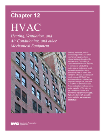
Example with varying flow over 1 yearThe example below is calculated on the basis of pumpcharacteristics obtained from a pump data-sheet. (45kW). The same examples of calculations can be usedin the case of fan characteristics.The result obtained is savings in excees of 50% at thegiven flow distribution over a year, corresponding to8,760 hours.Typically, the example calculated below results in apay-back period of one year - depending on the priceper kWh and the price of the frequency converter.Energy savingsThis figure compares flow regulation via valves andwithout speed control with flow regulation via afrequency converter.Pump characteristicsPshaft Pshaft outputFlow distribution over 1 0202020100438131417521752175217528760Valve regulationPowerConsumptionkWhA1 - 5623,040.296275.064MG.60.B1.02 - VLT is a registered Danfoss trademarkFrequency converter controlPowerConsumptionA1 - .3883,56.132124.1739Introduction toHVACVLT 6000 HVAC
VLT 6000 HVAC Better regulationIf a frequency converter is used for regulating the flowor pressure of a system, improved regulation isobtained which can be adjusted very precisely.A frequency converter can vary the speed of the fan orpump infinitely, thereby obtaining infinitely variablecontrol of flow and pressure.Furthermore, a frequency converter can quicklyregulate the speed of the fan or pump, so as to adaptit to new flow or pressure conditions in the system.More traditional, mechanical flow or pressureregulating systems tend to provide slow, inaccurateregulation if compared with that of the frequencyconverter. Frequency converters generate less noiseIf the speed of a fan is changed, the sound levelchanges, too. If the rpm figure is reduced by 50%from the rated rpm value, the sound level will go downby approx. 16 dB(A).The formula is:55 log x ( ) dB(A)n1n2 Regulating dampers and valves no longerrequiredSince the flow or pressure can be regulated bymeans of the frequency converter, no regulatingdampers and valves are required in the system. Cos ϕ compensationGenerally speaking, a frequency converter with a cosof 1 provides power factor correction for the cos ϕ ofthe motor, which means that there is no need tomake allowance for the cos ϕ of the motor whensizing the power factor correction unit. Star/delta starter or soft-starter not requiredWhen larger motors are started, it is necessary inmany countries to use equipment that limits thestart-up current. In more traditional systems, a star/delta starter or soft-starter is widely used. Suchmotor starters are not required if a frequency converter is used.As illustrated in the figure below, a frequency converter does not consume more than rated current. Simpler installation when using a frequency converterA frequency converter can replace a traditionalregulating system, in which mechanical dampers andvalves are used for regulating flow or pressure.The great advantage involved in using a frequencyconverter is that the system becomes simpler, since alot of the mechanical and electrical equipment is nolonger required. V-belts no longer requiredIn mechanical regulating systems, where the fan isdriven by V-belts, it is necessary to change beltpulleys in order to adjust the fan speed to match theneces-sary maximum load. Using a frequency converter, the V-belts can be replaced by directly driven motors, whose speed is changed simply by means of thefrequency converter.The efficiency of the system improves and the entireinstallation takes up less space. There is no dust fromthe V-belt and less maintenance.101 VLT 6000 HVAC2 Star/delta starter3 Soft-starter4 Start directly on mains Cost of using frequency converter not higherThe example on the following page shows that a lotof equipment is not required when a frequencyconverter is used. It is possible to calculate the costof installing the two different systems. In the exampleon the following page, the two systems can beestablished at roughly the same price.MG.60.B1.02 - VLT is a registered Danfoss trademark
VLT 6000 HVACD.D.C.E.M.S.V.A.V.Sensor PSensor T Direct Digital Control Energy Management System Variable Air Volume Pressure TemperatureIntroduction toHVACequency converterfrequency W ithout a frThe figure shows a fan system made in the traditionalway.equency converter W ith a frfrequencyThe figure shows a fan system controlled by VLT 6000 HVAC frequency converters.MG.60.B1.02 - VLT is a registered Danfoss trademark11
VLT 6000 HVAC Control principleA frequency converter rectifies AC mains voltage intoDC voltage, after which the DC voltage is converterinto an AC current with a variable amplitude andfrequency.1. Mains voltage3 x 200 - 240 V AC, 50 / 60 Hz3 x 380 - 460 V AC, 50 / 60 Hz.2. RectifierA three-phase rectifier bridge that rectifies ACinto DC current.3. Intermediate circuitDC voltage 2 x mains voltage [V].4. Intermediate circuit coilsSmooth the intermediate circuit current and limitthe repercussive effect of harmonic currents onthe mains supply.VVCPLUS control principleThe VLT 6000 HVAC has an inverter system calledVVCPLUS, i.e. a further development of Voltage VectorControl (VVC). This principle is known from suchunits as Danfoss VLT 3500 HVAC.VVCPLUS controls an induction motor by energizing itwith a variable frequency and a voltage that matchesit. If the motor load is changed, the magnetisationand speed of the motor change too. Consequently,the motor current is measured continuously and theactual voltage requirement and slip of the motor arecalculated from a motor model. Motor frequency andvoltage are adjusted to ensure that the motoroperating point remains optimised under varyingconditions.12The motor is thus supplied with variable voltage andfrequency, which enables infinitely variable speedregulation of three phase, asynchronous standardmotors.5. Intermediate circuit capacitorsSmooth the intermediate circuit voltage.6. InverterConverts DC voltage into variable AC voltagewith a variable frequency.7. Motor voltageVariable AC voltage, 10-100% of the supplyvoltage.8. Control cardThis is where to find the microprocessor thatcontrols the inverter which generates the pulsepattern by which the DC voltage is converted intovariable AC voltage with a variable frequency.The development of the VVCPLUS principle is the resultof a wish to maintain robust, sensorless regulationthat is tolerant to different motor characteristicswithout motor derating being required.First and foremost, the current measurement and themotor model have been improved. The current is splitinto magnetising and torque-generating parts andprovides for much better and quicker estimation ofthe actual motor loads. It is now possible tocompensate much better for frequent load changes.MG.60.B1.02 - VLT is a registered Danfoss trademark
VLT 6000 HVACAfter automatic motor adaptation, VVCPLUS will help toensure extremely accurate motor control.Because of the good load estimation achieved, anenergy optimisation algorithm can be integrated - onethat is effective regardless of the load characteristic.--The "flying start" function enables the unit tocatch a rotating fan.Automatic ramp up/down to ensure that theVLT 6000 HVAC will not trip during accelerationor deceleration.All standard units have three integral, serialprotocols - RS 485 FC protocol, Johnson’sMetasys N2 and Landis/Staefa FLN.Communication option cards that can beconnected are LonWorks, Profibus for the VLT6000 HVAC.Introduction toHVACGood torque control properties, smooth transition tocurrent limit operation and robust pull-out protectionare ensured.Advantages of the V V CPLUS control system:- Good compensation for step loads- Great tolerance towards varying motorcharateristics- Controlled transition from normal operation tocurrent limit operation (and vice versa)- Quick response from speed reference to full motorshaft torque- Reliable pull-out torgue protection throughout thespeed range, also in the case of field weakening- Torque control, comprising control of both thetorque-generating and the magnetisingcomponent of the currentProgrammable control inputs andsignal outputs in four SetupsVLT 6000 HVAC uses a digital technique whichmakes it possible to program the different controlinputs and signal outputs and to select four differentuser-defined Setups for all parameters.As standard, VLT 6000 HVAC comes with a numberof integral components that would normally have tobe acquired separately. These integral componentsare space-savers that simplify installation, since VLT6000 HVAC fulfills most requirements without anyadditional components.Protection against mains interferenceVLT 6000 HVAC is protected against the transientsthat occur in the mains supply, e.g. when switchingpower factor correction or if fuses blow whenlightning strikes.The use of a VLT 6000 HVAC offers the followingadditional advantages:- All unit types are available with an integral RFIfilter, complying with EN 55011 class 1-A in thecase of a 150 m screened/armoured motor cableand EN 55011 class 1-B in the case of ascreened/armoured motor cable up to 50 m long.- Detachable LCP control panel with Hand-Off-Autobuttons and a
Quick Setup Guide: Helps you get your VLT 6000 HVAC installed and commissioned quickly. Design Guide: Used when designing systems with VLT 6000 HVAC. The Design Guide gives all useful information about the VLT 6000 HVAC and HVAC systems. There is a selection tool for you to choose the right VLT 6000 HVAC with the relevant options and modules.