Transcription
Behavior Research Methods, Instruments, & Computers2002, 34 (4), 561-572A laser-based eye-tracking systemKENJI IRIE, BRUCE A. WILSON, and RICHARD D. JONESUniversity of Canterbury, Christchurch, New Zealandand Christchurch Hospital, Christchurch, New ZealandPHILIP J. BONESUniversity of Canterbury, Christchurch, New ZealandandTIM J. ANDERSONChristchurch Hospital, Christchurch, New ZealandThis paper reports on the development of a new eye-tracking system for noninvasive recording of eyemovements. The eye tracker uses a flying-spot laser to selectivelyimage landmarks on the eye and, subsequently, measure horizontal, vertical,and torsional eye movements. Considerable work was requiredto overcome the adverse effects of specular reflection of the flying-spot from the surface of the eye ontothe sensing elements of the eye tracker. These effects have been largely overcome, and the eye-trackerhas been used to document eye movement abnormalities, such as abnormal torsional pulsion of saccades, in the clinical setting.Quantitative eye movement measurements can provideinvaluable information for the diagnosis and study of various neurological disorders and are an essential tool in fundamental research on the oculomotor system (Leigh &Zee, 1999).Human eye movements can be broken down into threedistinct axes of rotation: horizontal, vertical, and torsional.Although horizontal and vertical eye movements are truerotations around the center of the eye, these can be usefullydescribed as translational, albeit with units of angularmeasure. The primary function of these movements is tobring and keep the center of images of interest on the eye’sfovea. Eye movements can have velocities up to 600º/sec(Leigh & Zee, 1999) and power spectral components up to50 Hz (spectral analysis of own data). Eye movementsoften contain both translational and torsional components.Some torsional abnormalities, such as pathologicaltorsionpulsion (Anderson & MacAskill, 1998), may be presentonly during translational eye movement.A number of methods have been proposed or used formeasuring eye movements, each with different featuresand levels of performance. Of particular importance iswhether eye movements need to be measured only in onedimension (e.g., horizontal), in two dimensions (horizontal and vertical), or in three dimensions (translational plustorsional). The target goal of our laser-based eye tracker isThe laser-based eye tracker described in this paper is not available asa commercial product, but consideration is being given to pursuing thispossibility pending the outcome of further development work. K.I.,R.D.J., P.J.B., and T.J.A. are members of the Christchurch MovementDisorders and Brain Research Group. Correspondence concerning thisarticle should be addressed to K. Irie, Lincoln Technology,P. O. Box 133,Lincoln, Christchurch 8152, New Zealand (e-mail: iriek@lincoln. ac.nz).to track eye movements in three dimensions. A summary ofthe most common methods for measuring three-dimensional(3-D) eye movements follows.Several methods are based on tracking contact lenses.The performance of these systems is typically very good,but all are invasive, uncomfortable, and often require atopical anaesthetic. Matin and Pearce (1964) developed ascleral contact lens system that uses a pair of noncoplanar4-mm-diameter mirrors embedded in the surface of thelens on opposite sides of the pupil. Their system has a resolution of 0.00028º within a range of 610º for all three dimensions and has a flat frequency response up to 1.3 kHz.Robinson (1963) used a pair of magnetic search coils placedaround the head to induce an electrical current into a pairof orthogonal magnetic coils placed in a scleral contactlens. Translational eye movements could be measureddown to 0.25º over a 620º range and torsional movementscould be resolved down to 0.0042º. Their system had a bandwidth of 1.0 kHz.Methods based on tracking the retina (Young & Sheena,1975) and the fundus (Kawai, Tamura, Kani, & Kariya, 1986)have been developed that can achieve bandwidths up to60 Hz (Mulligan, 1997), although most fail to exceed 5 Hz.Photographic images have also been used to measure eyemovements, but the long postprocessing time required todevelop and analyze the photographs severely limits thisapproach.In the last 5 years or so, video-based systems have takenon a prominence in the eye-tracking world. The advent ofdigital recording devices (CCD and CMOS cameras) hasled to video-based systems’ becoming smaller, more reliable, and substantiallyfaster than earlier analoguerecordingdevices. An example is Alphabio’s “Eyeputer” (http://www.electronica.fr/alphabio), which can sample at up to 480 Hz561Copyright 2002 Psychonomic Society, Inc.
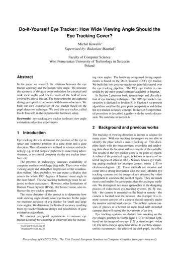
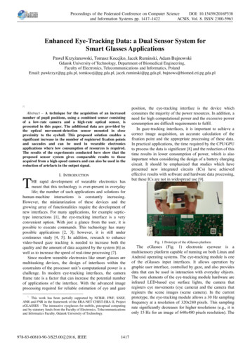
562IRIE, WILSON, JONES, BONES, AND ANDERSONwith a horizontal range of 630º, vertical range of 620º,and a torsional range of 645º. It has a precision of 60.3ºtranslationally and 60.2º torsionally at this sample rate,although the horizontal and vertical precision can be improved to 60.1º by reducing the sample rate to 60 Hz.Other manufacturers of camera-based systems includeApplied Science Laboratories (http://www. a-s-l.com),SKALAR Medical BV (http://www.wirehub. nl/ skalar),SensorMotoric Instruments (http://www. smi.de), andChronos Vision GmbH (Clarke, Ditterich, Drüen, Schönfeld, & Steineke, 2002).Prior to the development of high frame rate video-basedeye trackers, it was not possible to measure high-bandwidthsaccadic eye movements in three dimensions by noninvasive measures. Consequently,in 1994, we commenced development of a high-speed 3-D laser-based flying-spoteye-tracking system (Jones, Wilson, & Bones, 1996; Wilson, Anderson, Preddie, Jones, & Bones, 1996a, 1996b;Wilson, Jones, & Bones, 1995). By partially imaging theeye with a low-power eye-safe laser, it was recognized thatit would be possible to achieve high-speed,high-bandwidthnoninvasive 3-D eye tracking with only a fraction of thedata processing that would be required for processing fullvideo images of the eye. The spatial resolution is limitedonly by the laser spot size and the sampling frequency ofthe sensing system. The resolution in time is limited onlyby the speed of the sensors detecting the backscatteredlight, the bandwidth of the mechanical deflection apparatus, and the real-time computing capacity. This paper describes our laser-based eye-tracking system and, in particular, outlines some of the major obstacles met along theway and how they have been overcome to achieve a system with a performance suitable for both clinical and research applications.As far as the authors are aware, this isthe first eye tracker to use a laser for tracking 3-D eyemovements.Eye-safe LaserMirrorServo DriversSYSTEM DESCRIPTIONSystem OverviewThe eye tracker is essentially a specialized flying-spotscanner and consists of four main subsystems.1. A 650-nm wavelength, 1-mW red laser (attenuated to0.15 mW) focused to produce an illuminationspot of 53 mmon the eye (complying with Australian Standard AS2211[1991] for laser safety; Eckert, 1996).2. Mirrors that steer the small spot of illuminationacross the eye. The beam-steering system consists of twogalvanometer-driven beam-steering mirrors, servo controllers, and a digital-to-analogue converter. The mirrorsare located above the subject’s eye.3. A receiver that measures the reflected light from theeye, consisting of two sampling channels, each with twophotodiode sensors. The signals from the photodiodes arepassed through a transimpedance amplifier and a variablegain amplifier before being digitized by an analogue-todigital converter card on a PC running MS-DOS.4. A computer that controls the scanner, stores andprocesses data, and interacts with the user. The eye trackersoftware tracks the pupil in real time and directs the beamsteering mirrors to keep a laser scan pattern centered onthe pupil. The system currently operates at 169 scans persecond. The torsional movements are too computationallyexpensive to perform in real time on the current hardwareand are calculated off line.A block diagram of the eye tracker is shown in Figure 1.The headset of the eye tracker can be seen modeled in Figure 2.Scan cycle. The scan cycle is a series of sweeps to partially image the eye so that the eye’s translational and torsional position can be determined. The eye tracker determines the position of the eye on the basis of a horizontalsweep, a vertical sweep, and a circular sweep. In esSyncx-axis ScannerHalf SilveredMirrorInterruptEye TrackerSoftwarey-axis ScannerPhotodiodeArray ( x 4)EyeGainTriggerAntialiasingFilterA/DConverterEye MovementDataImageDataAmplifiersPentium-Based PCFigure 1. Block diagram of the eye tracker system.HardDisk
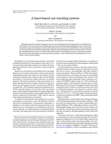
A LASER-BASED EYE-TRACKING SYSTEMFigure 2. Front view of the eye tracker headset.to these three sweeps, there is a fly-back period betweensweeps to position the spot ready for the next scan. Thereare, therefore, six operations, or phases, that make up eachcycle of measurement. Each sweep over the iris and pupilprovides an image of the reflectivity of the eye along aline. Figure 3 shows the trajectory of the laser spot throughthese six phases of the scan cycle. Phase 1 moves the beamto the start point of the vertical sweep, whereas Phase 2 isthe vertical sweep across the iris and pupil. From this ver-563tical sweep, the edges of the pupil are found, and thus, thevertical center of the pupil can be located. The setup forthe circular sweep is performed in Phase 3, and Phase 4records the iris pattern over a 270º arc. Torsion of the eyeis determined by cross-correlation of consecutive circularsweeps. Phase 5 moves the beam to the start point for thehorizontal sweep, whereas Phase 6 is the horizontal sweepacross the iris and pupil. From this horizontal sweep, theedges of the pupil are found, and thus, the horizontal center of the pupil can be located.The size of the pupil can change over the course of themeasurement period, but abnormal pupillary shape (e.g.,ovoid) may result in small inaccuracies in estimation oftranslational and torsional positions. Rare defects of theiris, such as aniridia (congenital absence of iris), precludemeasurement of torsional movements.At the start of an eye movement recording session, thescan pattern is placed approximately over the subject’spupil/iris. The eye tracker is then allowed to “lock on” tothe subject’s pupil (and a position calibration performed)before eye movements are recorded. If the edges of thepupil are not detected in both the horizontal and the vertical sweeps over several consecutive scans, the eye trackerenters a search mode and actively seeks the pupil until it“locks on” to the subject’s pupil again.Data processing. The eye tracker software controls thecollection, processing, and storage of scan information.The eye tracker software tracks the pupil in real time anddirects the beam-steering mirrors to keep the scan patterncentered on the pupil. A typical example of a horizontal(or a vertical) sweep of the eye is shown in Figure 4. Thepupil is indicated by the low-level signal area in the center of the sweep. The iris is seen as the higher level signaleither side of the pupil region, and the edges of the pupilcan be seen as the sharp signal steps in between the irisand the pupil. The center position of the pupil can be de-Figure 3. The six phases of a scan cycle.
564IRIE, WILSON, JONES, BONES, AND ANDERSONFigure 4. A typical horizontal sweep recording from the eyetracker.termined from the top, bottom, left, and right edges of thehorizontal and vertical sweeps.The entire torsion estimation process is based on imaging features on the iris. The features are primarily composed of radial striations. By recording images of the iris,torsional eye movements can be estimated by correlatingsubsequent images with each other. Although this is a relatively straightforward process, it is too computationallyexpensive to be undertaken in real time on the currenthardware. Instead, the scans are written to hard disk, andthe circular sweeps are correlated off line to estimate torsional eye movements.OBSTACLESSpecular Reflections on Translational TrackingParamount in achieving a clinically useful performancefrom the eye tracker is achieving reliable and accurateAIncidentLaser BeamSpecularReflectionSensortracking of the pupil. Both translational and torsionalmeasurements are affected by the quality of the pupiltracking. Initially, the eye tracker performed erratically,owing to its being unable to reliably track translational eyemovements. Specular reflections were determined to be amajor cause of tracking error as a result of the laser beam’sreasonably frequently reflecting directly off the eye surface onto one or more of the four sensors. Figure 5 illustrates the specular reflection process. The sensors hadbeen chosen and positioned so as to best detect the backscattered light from the eye but became saturated when themuch higher intensity specular reflection passed ontothem. Two levels of specular reflection were identified:saturating specular reflection, which saturated the photodiode output from an entire sweep and occurred when the laserbeam reflected onto one of the photodiodes for 1–2 msec,and nonsaturatingspecular reflection, which affected onlythe part of the sweep that the specular reflection occurredupon. An example of saturating specular reflections upona horizontal sweep is shown in Figure 6. Figure 6A has astrong specular reflection occurring over the left boundarybetween the pupil and the iris. This biases the pupil edgedetection algorithm, which will inaccurately determinethe pupil position. Figure 6B has two strong specular reflections apparent through the horizontal sweep, occurringnear the edges between the pupil and the iris. This also biases the pupil edge-detectionalgorithm. The result of thesestrong specular reflections is gross oscillation or loss ofpupil tracking.A two-part solution was implemented to reduce the erroneous eye tracking caused by specular reflection. First,the four sensors were placed around the eye to utilize thedual-channel sampling capability of the eye tracker system so as to ensure that at least one sampling channel isfree from specular reflections at all times. With the sensors positioned around the eye as shown in Figure 7, a horizontal sweep can saturate only one of the sensor pairs atBIncidentLaser k-scatteredlightFigure 5. Diagram demonstrating (A) how specular reflection occurs and (B) how certain angles of incidence cause specular reflection to directly impose on a sensor.
A LASER-BASED EYE-TRACKING SYSTEM565Figure 6. Horizontal sweep recordings from the eye tracker on the translational eye movement simulator showing saturating specular reflections: (A) a specular reflection occurring during a scan of the pupil and (B) two specular reflections, one on the pupil/iris boundary and one on the iris.any given time, since the projected specular reflection is aslightly curved horizontal line. Similarly, during a verticalsweep, only one sensor (and, therefore, one sampling channel) can be saturated at any given time, since the projectedspecular reflection is a slightly curved vertical line.The second part of the solution was to minimize the effect of any remaining specular reflections. By utilizing thedual-channel sampling capability of the eye tracker, manyof the unwanted effects of saturating specular reflectionswere overcome by developing an algorithm capable of detecting and removing data contaminated by saturatingspecular reflections.Figure 8 shows the major components of the samplingand channel selection subsystem of the eye tracker implemented to minimize the influence of any remaining saturating specular reflections. The optics have been carefullypositioned so as to ensure that at least one of the samplingchannels is free from specular reflection during any sweep.Data from the sensor pairs are summed in hardware on theeye tracker headset and are sampled by the A/ D converterboard in the eye tracker PC. The channel selection algorithm is passed data from the two sampling channels. Thetwo data streams (each 8-bit resolution) are checked forany saturation (i.e., signal levels of 255), and there arefour possible resulting cases: Both channels are free of saturations; Channel 1 contains saturations, whereas Channel2 does not; Channel 2 contains saturations, whereas Channel 1 does not; and both channels contain saturations. Todetermine the position of the center of the pupil, the algorithm selects the channel with no saturation and the widestpupil width detected.Distortions Affecting Torsional TrackingThe flying-spot approach to measuring eye movementsinherently brings several types of distortion into the torsional image. All image-based systems are susceptible tospecular reflections from the eye that may render part ofthe torsional image unusable.A scanning eye positiontracking system (as opposed to an absolute eye position measurement system, such as some contact lens systems andthe video-based systems) suffers from additional time delays in the tracking feedback. These time delays can distortthe recorded data and reduce the accuracy and reliabilityof the torsional eye tracking. Geometric distortions canalso occur because of the spherical imaging of the surfaceof the eye. Each of these distortions, although independent of each other, may occur at the same time. Also, inherent in the eye tracker sampling process is an intensitygradient (brightness variation) along the recorded imagethat is dependent on the sensor positions relative to thescan pattern position. This implies that not only do the effects of the distortions need to be reduced, but also therecorded data need to be filtered to remove the intensitygradients, which can severely bias the cross-correlationalgorithm.The most destructive distortion by far is the specular reflections. Specular reflections are additive, and image datacorrupted by saturating specular reflections from the sur-Figure 7. A set of sensor positions with a good balance betweenspecular reflection minimization and signal levels. The sensorsare placed 1–2 cm in front of the subject’s eye.
566IRIE, WILSON, JONES, BONES, AND ANDERSONSensor Pair 1Test forchannelsaturation0Sensor Pair 2Pupil EdgesPupil EdgesDual-channel sampling withOptics with minimaloccurrence of specular hardware summers.reflection, ensuring atleast one channelremains uncorruptedby specular reflectionswhen the scan pattern iscentered on the pupil.Channel selection for specular reflection free data(chooses neither channel if both channels containspecular reflection saturations).Figure 8. The dual-channel sampling and channel selection eye tracker subsystem.face of the eye cannot be recovered. However, they severely bias the cross-correlation algorithm and need to beremoved. Shown below in Figure 10A is a torsional recording saturated by specular reflection (further specular reflection in a torsional recording can be seen below in Figure 12A). As the cross-correlation function multiplies thetwo signals to be correlated, the removal of the effect ofthe saturating specular reflection can be achieved by setting areas of saturating specular reflection to zero . This isachieved by multiplying the original signal with a masksignal consisting of 1s where nonsaturated data are presentand 0s where saturation occurs. Saturations are detected assignals equal to the limit of the 8-bit A/D output (integervalue, 255). The setting of values within signals to 0 canbias the cross-correlation function. The result of the crosscorrelation needs careful unbiasing to ensure that the removal of saturating specular reflections does not dominatethe cross-correlation.In order to better illustrate this, a series of crosscorrelations is shown in Figure 9. Figure 9A shows thecross-correlation of series of two rectangular signals. Theresult of the cross-correlation is a triangular shaped signal.This represents the bias inherent in noncircular correlations. The result from the cross-correlation should be ahorizontal line with no peak, signifying that the two inputrectangular signals are equal across their entirety. Theright-hand diagram of Figure 9A is the triangular shapedcross-correlation result divided by itself. Dividing the results of cross-correlations by this reference weighting signal unbiases the cross-correlation.Figure 9B shows the same cross-correlation process asin Figure 9, but with two strong features added to the original input signals. The result of the cross-correlation is aslightly wavy triangular shape. The result is then dividedby the reference weighting signal, and the cross-correlationshown on the right of Figure 9B. The peak of the result isin the very center of the signal, showing that the two inputsignals have the highest correlation when they coincide.An example of the problem of setting values within theinput signals to 0 is shown in Figure 9C. Ten samples onthe right-hand side of one of the input signals have beenarbitrarily set to 0 to simulate the removal of a saturatingspecular reflection. The resulting biased and unbiasedcross-correlations are distorted, and the peak that shouldbe located in the center of unbiased cross-correlation isreduced and no longer the maximum point of the crosscorrelation.The cause of the distortion is due to the 0-values introduced into the signal. One solution that would improve theresult of the cross-correlation is to change the referenceweighting signal to incorporate the effect of adding 0values to the signals. The reference weighting is formed
A LASER-BASED EYE-TRACKING SYSTEM567Figure 9. A series of diagrams illustrating the use of weightings to unbias noncircularcross-correlation results. (A) generation of a reference weighting that can be used to unbiasother noncircular cross-correlations of the same length and same overall signal level. (B) Twosignals that when unbiased by the reference weighting shown in panel A have a peak in thecenter of the cross-correlation result, meaning that the signals are best correlated when thereis no offset between the two signals. (C) The addition of 0-values within one of the input signals to simulate specular reflection removal alters the cross-correlation result unbiased withthe reference weighting shown in panel A. (D) The generation of a new weighting to unbiasthe cross-correlation shown in panel C. (E) The cross-correlation of the signals shown inpanel C with the new weighting signal unbiasing the result. The peak of the unbiased signalis now back in the center of the result, meaning that the signals are best correlated whenthere is no offset between them.by the cross-correlation of two signals sampled at Level 1,each being the same length as the input signals. A modification to the input signals of the reference weightingcross-correlation can be made to incorporate the areas ofthe signals being unbiased that have been set to 0. Figure 9D illustrates the production of a new weighting signal, with one of the input signals having 0-values in thesame place as the signal being unbiased. The resultingweighting signal is triangular in shape with ridges. Whenthe result of the biased cross-correlation in Figure 9C isdivided by the new weighting signal, the result is a muchmore pronounced center peak, as shown in Figure 9E,which is once again the maximum point of the crosscorrelation.The process of removing saturating specular reflectionsgives a substantial improvement in the torsional results.Without this process, torsional estimation would tend to follow the paths of specular reflection that are almost alwaysseen in torsional imagesIntensity gradients in torsional signals can bias thecross-correlation process and produce erroneous results.The gradients occur because the sensor coverage of theeye is uneven, meaning that average light levels throughout the recorded data can vary. However, the gradients arelow frequency in nature and can be removed with a highpass filter (a 32-tap Hamming filter with a normalizedcutoff frequency of 0.15 fS , where fS is the sampling frequency, was used). Its performance was, however, severely
568IRIE, WILSON, JONES, BONES, AND ANDERSONFigure 10. Diagrams illustrating the filtering process to remove intensity gradients on the torsional recordings. (A) Raw torsional recording including two specular reflections. (B) The torsionalrecording with linear interpolation over areas of specular reflection. (C) The signal shown in panelB filtered with a 32-tap Hamming filter (v 5 0.15). (D) The filtered signal with the original areasof specular reflection set to 0.affected by the boundary effects generated by specular reflections or removal of specular reflection by setting values to zero. Prior to filtering, saturating specular reflectionis cut out and replaced with data linearly interpolated fromthe points either side of the areas of specular reflection.The linear interpolation maintains continuity and, therefore, reduces the boundary effects of discontinuous datawhen the signal is filtered. Figure 10 illustrates the filtering process used to remove intensity gradients from eyetracker torsional data.EYE-TRACKER PERFORMANCEThe performance of the laser-based eye tracker has beenmeasured both on artificial eye movement simulators andwith human subjects.Eye Movement SimulatorsThe eye tracker’s performance in both translational andtorsional tracking has been quantified using two prototypeartificial eye movement simulators able to provide repeatable and controllable eye movements. The first simulatorgenerated translational movements over a 25º (radial)range and was capable of oscillating the eye at 10 Hz. It consisted of a prosthetic eye with high-speed servomotorscontrolling the horizontal and vertical eye movements, asis shown in Figure 11.The second simulator generated high-speed translational and torsional movements and was constructed of arotating plate with a positionable prosthetic iris and pupil.The simulator was capable of 47-Hz horizontal, vertical,and torsional movements. The simulators were used to determine the eye trackers maximum eye tracking velocity,bandwidth, resolution, noise, and range. The eye trackerwas able to track translational movements of up to 660ºat velocities of 900º/sec and torsional movements of up to688º at velocities of 850º/sec. The performance characteristics of the eye tracker are shown in Table 1.The torsion estimation algorithm is reliant upon accurate positioningof the torsional sweep when recording theiris pattern. During translational eye movement, the scanpattern tracks the pupil as it moves, but the positioning ofthe torsional sweep becomes progressively offset as translational velocity increases. This affects the torsion estimation cross-correlation algorithm and results in an offset inthe torsion estimation.With the current scan rate of 169 scansper second (the maximum rate of real-time computationwith the current Pentium 100 PC), torsion estimation isaccurate for translational eye movements of less than70º/sec. This could be improved by rearranging the eye
A LASER-BASED EYE-TRACKING SYSTEMy-axis Servo atorY-inputy-axis ServoPositionx-axisRotationMicrochip ial Eyex-axis ServoPositionSignalGeneratorX-inputx-axis Servo MotorFigure 11. Block diagram of the translational eye movement simulator.track scan pattern so that the torsional sweep is performedfirst (to minimize the time for eye movement between thepupil position detection and the torsional sweep) or by increasing the scan rate by increasing computing power. Therecording is from the translational eye movement simulator performing 50º saccades at a velocity of approximately140º/sec.Normal SubjectsEight normal subjects were tested to evaluate the eyetracker’s tracking ability, range, and noise. The test groupconsisted of 4 females and 4 males, with an average ageof 30 years (range, 18–60 years) and a wide range of eyecolors. A flat board 1.2 m square containing a set of eightfixed viewing points (positioned 20º from central fixa-tion) was used to guide the subjects’ eyes in different patterns of up to 620º to generate translational movements.The subjects tilted their heads from side to side (i.e., rotation of the head about the naso-occipital axis) to generatetorsional ocular counter-roll. Data without large glitchesor loss of tracking was obtained from 5 subjects when eyemovements were limited to 614º horizontally and 614ºvertically (in 2 of these 5 subjects, 625º horizontally andvertically were achieved). Translational performance limitations arise from obstruction of the laser beam by eyelidsand eyelashes and, hence, varied from person to person.Enhancements to the mirror/sensor part of the systemshould be able to improve the range of eye movements forthe majority of subjects. Figure 12 shows a torsionalrecording of ocular counter-roll from a normal subjectTable 1Performance Summary of the Eye TrackerTracking speed:Range (simulators):Range (humans):Resolution:Bandwidth (3 dB):Noise (stationary simulators):Noise (humans focusingon stationary point object):Tracking :Translational Performance900º/sec (3-mm pupil diameter)660º radiusat least 614º horizontal/vertical (20º oblique)0.17º of arc (limit of 8-bit sampling resolution)horizontal, .47 Hzvertical, 30 Hzhorizontal, 0.13º RMS (8 of arc)vertical, 0.12º RMS (7 of arc)horizontal, 0.12º RMS (7 of arc)vertical, 0.13º RMS (8 of arc)Torsional Performance850º/secminimum 630º, tested on simulators on movements up to 88º1.05º without interpolationunable to test with current simulators; expected to match or better thetranslational bandwidth (.47 Hz); posttorsional filter cutoff set to 40 Hz, forremoval of high-
tiallyimage the eye so thatthe eye's translationaland tor-sionalpositioncan be determined.The eye tracker deter-mines the positionof the eye on the basis of a horizontal sweep,a verticalsweep,anda circularsweep. In addition Figure 1. Block diagram of the eye tracker system. Eye-safe Laser Half Silvered Mirror Photodiode Array (x4) Eye x-axis .