Transcription
INSTALLATION GUIDEGuide for your AZ-125, Azimuth Drive Solar TrackerCongratulations, you have purchased the finest solar tracker available. With proper installation, your tracker willprovide years of trouble-free service while maximizing your solar power production.Your tracker may include one of the following options: (Check your packing slip.): Stainless Steel Hardware Option - Recommended for high humidity and salt laden environments. Wattsun Voltage Converter Option - Required for PV Systems other than 24 VDC. Manual Control Option - Exterior switches so you may manually operate the tracker.The tracker comes complete with all the hardware necessary for assembly and mounting the PV modules. TheWattsun Tracker requires a length of Six-Inch ID Schedule 40 Steel Pipe for use as the pipe mast.Specifications for the pipe mast can be found on the data sheet for this particular tracker. The steel mountingpipe and PV modules are not included. Your electrician should provide all additional array wiring, fusing,power disconnects, grounding equipment and electrical junction boxes.WARNING:If the Wattsun Azimuth Solar Tracker is not installed to manufacturer’s specifications, suchfailure to properly install unit may cause tracker malfunction and or serious bodily injury ordeath. This tracker moves, therefore the tracker should be situated away from anybody oranything that may come in contact with it as it moves.KEEP CHILDREN AWAY FROM TRACKER AT ALL TIMES.Array Technologies, Inc.3312 Stanford NEAlbuquerque, NM 87107Tel: 505-881-7567Fax: 505-881-7572URL: www.wattsun.com1
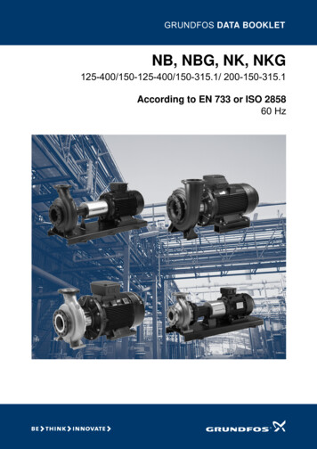
Copyright Array Technologies, Inc.All rights reserved.Wattsun is a trademark of Array Technologies, Inc.AZ-125 Azimuth Gear DriveSide ViewAZ-125 Azimuth Gear DriveFront ViewWattsun Solar Tracker Controller(Shown with Manual Control Option)Elevation Actuator for theDual-Axis OptionRemote Sun Sensor that connectsto the Wattsun Solar Tracker ControllerAZ-125 Installation Guide: Revision 6AUG 20092
WARNING TO ELECTRICIAN OR INSTALLER Please read this instruction manual completely. If you are unfamiliar with NEC compliant solar electric installation, thenconsult with the dealer that supplied your tracker. They should have theskill and expertise to supply you with the necessary wiring diagrams and theappropriate connection wire, grounding equipment, junction boxes and fusing. Failure to ground the array structure, including each module frame, thealuminum tracker frame, the drive head assembly and the pipe mast maymake the tracker susceptible to damage by lightning. Do not rely on the pipe mast to act as a ground rod. It is not a reliablesubstitute for a properly installed ground rod. Please send in the Wattsun Tracker Warranty Card. Array Technologiesdoes not share any of the information provided on the warranty card. Please leave this manual for the tracker owner(s). It is their property andwill help resolve any potential problems. Please provide the following information for the owner:Serial Numbers:Serial Number located on the controllerTracker Type: AZ-125Dual-Axis Option? YesController is powered from: Battery BankSystem Type: O ff-Grid/Remote Home Water PumpingPV Array:Serial Number located on the drive assemblyNo Array-Direct Grid-Intertie - no battery backup Other Grid-Intertie - battery backupPV System Voltage is VDCNumber of Modules:Module Manufacturer:Module Model:Mounting Pole Height above the Ground is: FT3
TABLE OF CONTENTSSECTIONTITLEPAGE1Installation of the Tracker Pipe Mast and Foundation.52Install the Azimuth Gear Drive Assembly on Top of the Pipe Mast63Install Single-Axis Bar Elevation or Actuator84Installing the Torque Tube & Module Support Frame Assembly115Installing the Tracker Controller176Power Connection to the Elevation Actuator247Power Connection to the Tracker Controller258Operating the Tracker Controller289Setting the Azimuth Drive Motor Limits2910W48-24 LVC: Pre-Regulator for 48 VDC PV Systems3111Manual Control Option3312Periodic Maintenance3413Suggested Grounding Methods for Wattsun Solar Trackers3514Warranty394
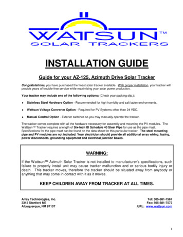
Section1Installation of Tracker pipe mast and foundationWARNING! WINDY CONDITIONS CAN EXERT EXTREME FORCES ON THE ARRAY, FOUNDATION,AND PIPE MAST OF YOUR TRACKER.1.1) Choose an optimum solar location to install the PV array for in the ground mounting. The location should befree from obstructions. Keep in mind that over a period of time, that trees, shrubs, etc. may grow enough toobscure the PV array from the sun. Consult with your dealer for proper tracker spacing and alignmentregarding multiple tracker installations.1.2) Dig an appropriate sized hole for your tracker’s foundation using a shovel, auger, or backhoe. The variablesthat affect the design of the foundation include: tracker size, pipe mast height, soil conditions, geographicallocation, weather and local building codes. Employ a qualified professional to design the foundation for yourtracker.1.3) A general rule of thumb is to have an equal amount of pipe underground as above the ground and a three-footdiameter reinforced concrete foundation. Please have a professional design the size and type of foundationrequired!1.4) Use the appropriate length of 6" ID, Schedule 40 Steel Pipe in order to leave the recommended maximumpipe mast height protruding from ground. Consult your specific Wattsun Technical Data Sheet for theappropriate mast height and pipe diameter size. Note: If the recommended pipe mast height is exceeded, itmay be necessary to telescope a larger diameter pipe in the lower portion and increase the foundation size inorder to withstand the increased forces exerted during windy conditions.1.5) Cut at least two pieces of re-bar or steel angle at lengths equal to the full diameter of the foundation. Weld rebar onto (or drill holes and insert re-bar into) the underground portion of the pipe so that the pieces of re-barform an ‘x’ pattern that remains parallel to the ground. When the tracker pipe mast is completely installed, there-bar will be perpendicular to the pipe and parallel to the ground and protrudes radially outward into theconcrete foundation. The re-bar acts as an "anti-rotation" device and will keep the pipe from spinning in thehole if the concrete shrinks back from the pipe.1.6) Set the pipe into the hole and pour concrete around the pipe until it completely fills the hole. Also pourconcrete into the pipe to secure the re-bar inserted in the bottom portion of pipe. Make certain the pipe isvertically plumb and allow concrete to set for at least 24 hours. If you fill the entire pipe mast with concrete,leave at least one foot of hollow pipe at top for azimuth drive assembly clearance.SIMPLIFIED TRACKER FOUNDATION DIAGRAM(Using recommended mast height from your Technical Data Sheet)Array Technologies, Inc. assumes no liability for your foundation installation. Please consult with a localprofessional or your Wattsun Solar Tracker Dealer to design your foundation!5
Section2Install the Azimuth Gear Drive AssemblyOn Top of the Pipe Mast2.1) Northern or Southern Hemisphere installations.AZ-125 Azimuth Gear Drive(Shown with HZ T Tube Saddle)Single-AxisElevation BarORDual-AxisLinear ActuatorFor Northern Hemisphere installations, point the motor/gear assembly to ‘true north’ * and tighten the fourset bolts to secure tracker to pipe mast. The set bolts should be tightened so that they dig into the pipe mast.For Southern Hemisphere locations, point the motor/gear assembly to ‘true south’ * and tighten the four setbolts to secure tracker to pipe mast. The set bolts should be tightened so that they dig into the pipe mast.Tropical and Equatorial Installations are discussed in Section 3* Note:True north and south differ from magnetic north and south and depends on geographical location.Locate ‘magnetic north’ or ‘magnetic south’ using a compass and adjust your tracker settingaccordingly. Your Wattsun Tracker Dealer can provide you with the Magnetic Declination for yourarea. The Array Technologies web site (www.wattsun.com) has links to geomagnetic data. You canfind, or calculate, the magnetic declination for any place on the globe.Perhaps the easiest way to find the North-South line is to get a copy of your local newspaper and findthe Sunrise and Sunset times. Determine the time (hour and minute) that falls exactly halfwaybetween Sunrise and Sunset. At the halfway or 'Solar Noon' point, anything that casts a shadow willdo so along a North-South line. Get a friend to help hold up a length of wood or a stick of conduitstraight up into the sky. Then stake out or mark the North-South shadow line.6
VERY IMP ORTANT! “OUT OF THE BOX” DRIVE ORIENTATIONWARNING! The AZ-125 Drive weighs from 130 to145 pounds! Do not use the Azimuth motor or trackercontroller as “lift handles.” You will damage the motor gearing or tracker controller if you put anyunusual force on them.The AZ-125 Drive orientation is preset at the factory and referenced to Solar Noon. The drive should be mountedfacing due South, (Due North in the Southern Hemisphere.).SET BOLTS: The 4 "cup point" set bolts "dig and cut" in to the 6" ID SCH40 Steel Pipe Mast. Tighten the set boltsso that they put strong and equal pressure on the pipe mast. Each bolt should "show" and equal amount ofthread when you are finished. Each set bolt should be tightened to 80 Ft-Lbs of torque.ROLL PIN: A three-eighths inch (3/8") diameter hole is predrilled in the midpoint of the south face of the drive. Thehole accommodates the 3/8" roll pin. Once you are sure that the drive is facing due South, you can use the hole asa guide to drill a three-eighths inch (3/8") diameter hole into and through the wall of the mounting pipe. Then tap inthe roll pin so that it penetrates through both the drive and pipe mast. Alternately, both holes could be threadedand a bolt could be used to "pin" the drive and mounting pipeJ-BOX & OTHER EQUIPMENT ON THE MOUNTING POLE: Any equipmentthat will be mounted on the pipe mast should be located on the North side(opposite of the roll pin hole), at least one foot down from the top of the pipe.That allows for our sleeve to fully seat on the pipe and that nothing physicallyinterferes with the tracking range of motion.7
Section3Install the AZ-125 SA Bar or Elevation ActuatorTHE AZ-125 DRIVE WEIGHS 130 to 145 LBS: You will have to be able to lift the AZ-125 Drive up, over and downon top of your mounting pole. Placing the drive on top of the pipe is at least a “two person” job. The drive is mucheasier to set using a boom and pulley arrangement or suspending it from a backhoe bucket or other appropriatemethod.Make sure that the drive “seats” completely over the pipe. Back out the 4 set bolts if necessary to make sure thatthey do no catch on the top of the pipe. The 4 "cup point" set bolts "dig and cut" in to the steel pipe. Tighten theset bolts so that they put strong and equal pressure on the pipe mast. Each bolt should "show" an equal amountof thread when you are finished. Each set bolt should be tightened to 100 Ft-Lbs of torque.-Move on to the Actuator Installation if you have the Dual-Axis OptionELEVATION BAR CONNECTIONS TO THE TRACKER DRIVEINSTALL THE ELEVATION BAR(Single-Axis with Manual Tilt Adjustment)Bolt the elevation bar to the pivot arms at the upper connection and the 10degree setting. This allows you to build the tracker frame in a nearly flatposition. The holes are drilled for tilts of 10 to 70 degrees in 10 degreeincrements. You may make seasonal adjustments for the array tilt. If youchoose to change the settings only twice a year then use a 40 degree tilt forSumer and a 50 degree tilt for Winter.8
ELEVATION ACTUATOR CONNECTIONS TO THE TRACKER DRIVEDo not unscrew the inner tube of the elevation actuator! This destroys the factory pre-set mechanical upperand lower limit switch settings. Install the elevation actuator. Center both the eyelet end (the top) of the elevationactuator inside the forks and the elevation actuator clamp eyelet (the bottom). Firmly tighten the locknuts on thebolt threads.UPPER CONNECTIONLOWER CONNECTIONMOTOR FACES UPADDITIONAL DETAILS9
Section4Install the Module Torque Tube & Support FrameSECTION 4 NOTES: Nearly every nut and bolt will be left "finger-tight" until all the modules are mounted andthe frame is "squared-up." So allow for a small amount of "play" when putting the array together. You willsnug up all the bolts and nuts when all the modules are mounted and the frame is complete.Installation Tip: The PV modules may be mounted to the rails at this time - prior to installation onto the torquetube assembly. This removes the difficulty of mounting each individual module to the rails while you workingoff a ladder or above your head.However, placing the heavier, assembled module sub-array onto the torque tube assembly requires at leasttwo people. For either application, the web of the module mounting struts must be oriented toward the outerends of the modules.AZ-125 HORIZONTAL TORQUE TUBE INSTALLATIONConsult the diagrams below for the bolt connections. Tighten the U-bolt Nylock nuts to 70 Ft-Lbs of torqueTIGHTEN NYLOCK 5/16” U-BOLT NUTS EVENLY.TIGHTEN EACH NYLOCK NUT TO 70 FT-LBS OF TORQUE.10
Procedure for Installing Solar Modules on Wattsun Tracker Universal RailsExamples of Three and Four Column Tracker FramesWattsun Tracker frames are manufactured to hold the solar modules in a rectangular grid. A pair of verticalmodule rails will mount a group of modules in “landscape” format. The completed frame is made up of one to fourpairs of module rails.Each rail is U-bolted onto the horizontal “steel spine” of the tracker called a torque tube. If the rails are longer thanten feet then an additional support under-angle is included – one for each rail. Wattsun Trackers come with all thehardware to assemble the tracker and mount the modules.Tools Required: Frame Assembly and Module MountingToolRequired to Fasten3/4 “ Open End Wrench7/16” Open End Wrench1/2 ” Open End WrenchRubber or Plastic Head MalletNylock Nuts for the Module Rail Assembly U-BoltFlange Nut for 1/4” x 3/4” Module Mounting BoltFlange Nut for 5/16” x 3/4” Module Mounting BoltSmall adjustments to shift the Rail Assembly sidewaysWe encourage installers’ to wear a Hard Hat!11
BUILDING THE FRAME AND RACKING THE MODULES:DO YOU MOUNT ONE PIECE AT A TIME OR BUILD tom up the Procedure is:Bolt Support Angle Tube Rail Washer NutSubArrayApproach:Requiresalotofpeoplepower. Notice that the rails bolt to the intermediatemodule holes. Lift by the tracker rails only, not themodule ically a 3-person job: 2 lifters, 1 bolter. Lift by thetracker rails only, not the module framesOne installer, one piece at a time approach.Modules are being used to “square-up: the frame.Notice how the modules overhang the Rails.The “one piece at a time” approach can get verytiring. The installer is working with their arms andhands above their head.TIP: Leave all frame and module bolts “fingertight.” Once you finish the frame building andmodule mounting, you can go back and “squareup” the array. Then tighten all nuts with a wrench.NOTE: If you ever “under populate” the arrayframe, leave any unused space at the top of theframe. If the frame is not totally filled out, then thegreatest weight should be on the lower sections ofthe frame.12
Step 1The modules get mounted to the rails using theintermediate holes. Locate the intermediatemounting holes on the frame of your module.In general, they are placed from 7” to 16” in on thelong side (Length) when measured from the frameedge short side (Width).Each manufacturer has unique hole patterns. Yourmounting holes are made to accommodate either1/4” or 5/16” module mounting bolts. The bolts aresupplied with your Wattsun Tracker.Step 2Identify your module mounting bolts and nuts fromthe hardware kit. The module bolts are labeled andare either 1/4” or 5/16” diameter.Note that both the interior faces of the nut and boltare made to cut into the module frame. They do notrequire any type of washer.Step 3There are four bolts and nuts per module. Premount the module bolts so that the serrated nuts willdig into the underside of the module frame.Do not tighten the bolt fully. Leave it about one fullturn loose so it will glide easily in the module track.13
Step 4Measure and record the “center to center” distanceof the intermediate mounting holes. This dimensionsets the spacing of the mounting rails.Each pair of mounting rails typically holds from 3 to 4large modules. Typical rail spacing might be from24” to 35” apart.Step 5Remove a pair of modules rails from the framebundle. They will be bolted on top of the torque tubeso that the “legs” of the channel face inward towardseach other.The bolts on in the top track are the modulefasteners and the bolts in the side track secure themodule rail support angle.Note that support angles are only shipped withmodule rails that are longer than 10 feet.( Cross section view of themodule rails and bolt connections )Step 6Pull the module rail u-bolts, washers and locknutsfrom the hardware kit. There will be one set of u-bolthardware per module rail.If your module rail is longer than 10 feet then therewill be a corresponding support angle in your framebundle.14
Step 7If you have a three column tracker(3 modules wide) then your first rail set will becentered over the drive head and straddle thecenterline of the torque tube.If you have a four column tracker ( 4 modules wide)then your first rail set will be to the right or left of thecenterline of the torque tube.(Step 1)Step 8Pass the u-bolt through the holes in the supportangle. Push the u-bolt up and around the torque tubeand into the receiving holes in the bottom of themodule rail.Place a 1/2” flat washer over each leg of the u-boltand then secure a 1/2” Nylock nut over each leg. Donot tighten the Nylock nut completely. Leave a littleslack so the rail assembly can be slid horizontallyalong the torque tube to accommodate your “centerto center” measurement.(Step 4)Step 9Carefully fold up the support angle so that it makescontact with the underside of the module rail. Thehole in the side face of the angle should be alignedover the side track of the module rail.The support angle connection to the side of themodule requires that you slide a 5/16” bolt along theside track until it aligns with the hole in the end of thesupport angle.Do not tighten the bolt completely. Leave a littleslack so you can square up the frame at the end ofthe installation.15
Step 10Use a tape measure and gap the module rails adistance equal to the “center to center” intermediatehole spacing. (Step 4)Be sure that you are spacing from the centers ofboth top tracks in the rails. You might have to loosenthe u-bolt Nylock nuts so that you can easily adjustthe rail assembly along the torque tube.The racked modules and frame will be squared up atthe end of the mounting procedure.Step 11Make sure that the tracker is in the “stow” or nearlyhorizontal position and that the elevation bar oractuator has been installed.Line up the module bolts into each track. You mighthave to spin the bolt a bit so that the square shoulderof the bolt line up in the slot. Push the moduleforward and repeat the process with the other side ofthe module.Once the module is properly positioned on the rails,tighten the serrated module nuts until they are fingertight.Step 12Continue populating the array with the railassemblies and solar modules. Even out thespacing between the module frames (typically 1/4” in1/2”) and square-up the frame assembly. Go backand tighten up all the bolts and nusts left intentionallyloose.Start with the rail assembly u-bolts Nylock nuts, thenproceed to the support angle fasteners (if provided)and finish up with each module mounting bolt andnut.16
Section5Installing the Wattsun Solar Tracker ControllerWARNING! PLEASE READ THIS GUIDE COMPLETELY BEFORE CONNECTING POWER TO THECONTROLLER. YOU CAN DAMAGE THE CONTROLLER OR INADVERTANTLY POWER UP THE TRACKERAND CREATE A HAZARDOUS SITUATION. NEVER APPLY POWER TO THE CONTROLLER OUTPUTWIRES! THE CONTROLLER WILL BE DAMAGED AND THE REPAIR CHARGE IS NOT COVERED UNDERWARRANTY.For Installations in the Tropics:(20 degrees North latitude to 20 degrees South latitude)Array Technologies does not encourage the use of Dual-Axis Trackers in “low latitudes.” Wattsun SingleAxis Trackers are preferred in the tropics. Contact Array Technologies for performance data andrecommendations.The azimuth tracker works by rotating the PV array about the pipe mast then tilting the array to the properelevation angle. Therefore, for installations near the equator it will be necessary to rotate the azimuth tracker 180degrees twice a year. Depending upon the time of year, trackers in this region will find the sun anywhere fromnorth, south, or directly overhead of its location, making manual rotation necessary.For example, at the equator rotation of the tracker will need to occur on the first day of spring and the first day offall. The array should point north on March 21st, and rotated 180 degrees to point south on September 23rd.To rotate the tracker on the pipe mast, loosen the four set bolts on the azimuth drive, rotate the tracker and retighten. Marking the pipe mast for the two yearly positions, aids in seasonal adjustment. You must also leavesufficient output wire lengths from the array to allow for rotation.24 VOLT TRACKER CONTROLLER SPECIFICATIONSController input power specifications:The input voltage range is 23 to 50 volts DC.Use a Wattsun Voltage adapter to power the controller for nominal voltages other than 24 VDC.Tracker controller wiring and drive motor wiring:Do not connect the motor output wire harness to a power source! Connecting any of the controller outputwires to the PV array or a power source will cause permanent damage to the controller and void thewarranty.Power supply connection options:The input power leads are Red (positive) and Black (negative) wires in the two-wire cable mounted on theleft-hand side of the controller chassis. The input wires are clearly marked with a tag.Power consumption, including motors:Less than 10 watt-hours per day.17
YOUR TRACKER CONTROL BOX IS PREINSTALLED ON THE AZ-125 DRIVE.The Tracker Controller is pre-mounted on thebase of the AZ-125 Drive. It is located justbelow the main worm gear housing.Remote SunSensormounts on thearray.Optional Manual Control Switch platemounts on the cover of the trackercontroller.WARNING!MAKE THE “POWER IN” CONNECTION LAST!DO NOT ENERGIZE THE WATTSUN SOLAR TRACKER CONTROLLER UNTIL YOU HAVE COMPLETEDTHE ENTIRE TRACKER INSTALLATION.THERE ARE TWO ADDITIONAL CONTROLLER CONNECTIONS THAT GET MADE BY THEINSTALLER:Sensor mounts on the top edge of the array.Center it on the top makes for a neat wirerun. The remote sensor wire plugs into thebase of the sensor. Twist the lock ring!If you have the Dual-AxisOption: There is a two-wire“pig-tail” that is prewired intothe azimuth motor. It needs tobe connected to the elevationactuator motor.18
WATTSUN TRACKER CONTROLLER: FUNCTION AND FEATURES.OVERVIEWWattsun Solar Trackers utilize a patented, closed loop, optical sensing system to sense the sun’s positionand track it. The sun sensors are mounted on the remote chassis and feed information to the controlelectronics about the direct component of sunlight available, the diffuse amount of sunlight, the total amountof sunlight as well as the differential amount of sunlight on opposing sensors. Based on this information, thecontroller seeks to equalize the sunlight received by opposing sensors for each axis.The controller circuitry automatically adjusts the tracker sensitivity. It increases the sensitivity with increaseddirect sunlight and decreases the sensitivity with scattered or diffused light - present during cloudyconditions. This enables the tracker to eliminate undue hunting in cloudy or overcast conditions when thesunlight is scattered. It also adjusts according to the total amount of light received by the sensors.When the tracker controller is connected to a battery bank or constant power source, the controller cansense sunset, and return to the sunrise position in the evening. When it is powered directly from the PVarray, the tracker returns to sunrise at first morning light. The controller uses energy integration circuitry,enabling the tracker to move with as little as 20ma of available current.The tracker controller sends a signal to the DC gear motor that moves the PV array to a perpendicularposition relative to the sun’s rays. The motors are small, fraction HP, low voltage, gear motors that move thetracker into position. The gearing is designed such that high winds or other forces cannot drive the trackerback. Because they are DC drive motors, one polarity moves them in the forward direction and reversing thepolarity moves them in the opposite direction. When the controller wants the tracker to move, it sends asignal of the appropriate polarity to the DC gear-motor. Once the tracker has moved to the “on track”position, the controller electrically “brakes” the motor to stop movement that results in greater trackingaccuracy.STANDARD FEATURES OF YOUR WATTSUN CONTROLLER Controller mounted on the drive for maximum accessibility. Sensor mounts independently of the main chassis. Dip switches to test the Azimuth and Elevation Limits. Dip switch to set nighttime Elevation (stow) position. Controller outputs are short circuit protected and will limit the output current to 3 amps. Inside controller chassis are light sensitivity adjustment potentiometers for Azimuth and Elevation. Controller is equipped with a 5-amp automotive spade type fuse (ATO) inside the controller chassis. Self-resetting thermal fuse that shuts off power to the tracker motors in case of obstruction. Filtering to protect the tracker motor against "noisy" PWM charge controllers. Improved lightning protection.DUAL-AXIS NOTESIn general, the controller prioritizes the movement of azimuth (east/west) axis. If the azimuth axis is not ontrack, the elevation axis will not function. Once the azimuth axis has locked onto the sun and stops moving,the elevation axis adjusts. If you power the controller from a battery bank or AC to DC power supply, you canchoose to allow simultaneous azimuth and elevation motion with a flip of a dip switch.NOTEPlease power the tracker from a constant power source – either a battery bank or from the grid. TheArray Direct method is not recommended for powering Azimuth-Drive Trackers. It limits the azimuthtracking to 180 degrees.19
Terminal1234Controller OutputWhiteGreenRedBlackMotorAzimuth DriveAzimuth DriveElevation ActuatorElevation Actuator20
5.1) THE AZMUTH MOTOR TERMINAL STRIP (PRE-WIRED AT THE FACTORY)It is unlikely that you will need to access the wiring inside the Azimuth Motor. The Azimuth Motor TerminalStrip is pre-wired at the factory. It serves as a central connection point for motor power wires. The 4-wireController output lead and the Elevation Actuator lead share entry into the Azimuth Motor Cover throughthe rain tight plastic strain relief.A four-wire lead enters in from the Controller and is divided into two pairs. The first pair (White & Green)controls the East-West Azimuth movement. The second pair (Red & Black) “passes through” and controlsthe North-South elevation movement. The Elevation Actuator power lead exits azimuth motor coverthrough the strain relief and will be connected to the actuator motor by the installer.AZ-125 AZIMUTH MOTOR WIRE CONNECTIONS21
AZIMUTH MOTOR: TERMINAL STRIP WIRING DIAGRAM(POWER CONNECTIONS ARE PREWIRED AT THE FACTORY)WARNING!THE LAST CONNECTION MADE IS FROM YOUR POWER SOURCE TO THE TRACKER CONTROLLER! DONOT ENERGIZE THE WATTSUN SOLAR TRACKER CONTROLLER UNTIL YOU HAVE COMPLETED THEENTIRE TRACKER INSTALLATION.22
5.2) MOUNTING THE REMOTE SENSORMOUNT THE REMOTE SENSOR ON THE TOP OF THE ARRAYThe sensor mounts on the TOP CENTER (or near the center) of the PV array. Most modules alreadyhave a hole in the frame that you can use. If your modules do not have an "end hole" then you will need todrill a 1/4" hole in the frame to mount the sensor. Slip a thin piece of wood between the module frame andthe back of the module. The wood "spacer" will keep you from inadvertently digging your drill bit into theback of the module once you have drilled through the frame.If the modules in your array mount in “landscape” format and you have aluminum “endcaps” at the top andbottom of the array, then use the endcap mounting bolt and a strut near the center of the tracker. Make surethat the sensor has a clear view of the sky.The wire coming from the sensor has a molded connector. It mates into the bottom of the controller. Thecontroller connector has a grove inside to properly align the mating pieces. Match up the “tongue andgroove” of both connectors, push them together and twist the locking ring to secure the connection.THE V3.3 SENSOR ORIENTATION IS DIFFERENT FROM THE EARLIER V3.x VERSIONS!The sensor needs to be above the plane of the array and have aclear view to the sky. Do not crowd it against the array or moduleframe. If the “eyes” don’t have the freedom to “see” the sun thanthe tracker will have a tendency to tip up.Be careful not to damage the sensor on top. It’s function controls“return to the east” at night.23
Section6Power Connection to the Elevation ActuatorWarning! Never apply power to the actuator until it has been securely bolted into place. The linearactuator will tend to "unscrew" and will destroy the preset limit switch settings.6.1) Loosen the 4 cover screws and remove the actuator cover. The plastic strain relief might be inverted toprotect it during shipping. Flip it around, reseat and snake the actuator power wire through the
free from obstructions. Keep in mind that over a period of time, that trees, shrubs, etc. may grow enough to obscure the PV array from the sun. Consult with your dealer for proper tracker spacing and alignment regarding multiple tracker installations. 1.2) Dig an appropriate sized hole for your tracker's foundation using a shovel, auger, or .