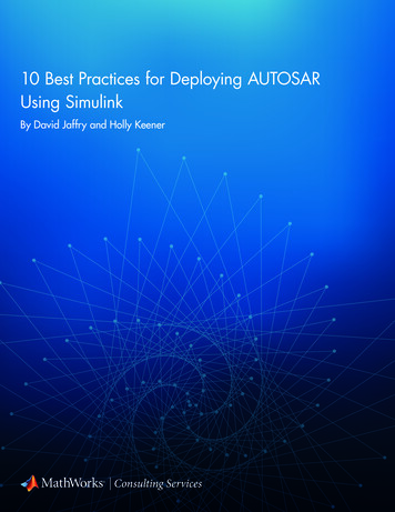
Transcription
BEST Robotic, Inc.MATLAB/Simulink Team TrainingProgramming With MATLAB/SimulinkSeptember 20, 2014BISON BEST1
What You’ll Need Minimum System Requirements Microsoft Windows XP or Later32-bit or 64-bit machineAdministrator Access on the PCInternet connection Software required MATLAB R2014a free version available itions/best-robotics/Registration and application required; approval expected in three days !Installation instructions will be provided in the approval email Associate to your license to your registered account Download and install MATLAB from the link provided (about 40 minutes) Activate the software Install the VEX Support Package and Companion App (about 15 minutes)September 20th, 2014Bison BEST2
Key Software LocationsAugust 1, 2010Copyright 2010 BEST Robotics, Inc. All rights reserved.3
Starting MATLAB Click on the MATLAB r2014a linkAugust 1, 2010Copyright 2010 BEST Robotics, Inc. All rights reserved.4
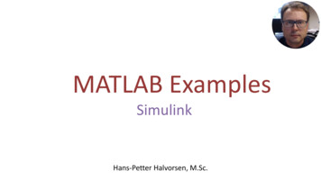
Something on MATLAB MATLAB Window Opens: MATLAB means MatrixLaboratory. It is textural programming environment. It can execute commands directly as typed in the commandwindow or run a script code from a saved fileAugust 1, 2010Copyright 2010 BEST Robotics, Inc. All rights reserved.5
For BEST Robotics tools Choose Apps from the main menuAugust 1, 2010Copyright 2010 BEST Robotics, Inc. All rights reserved.6
.Best Robotics tools Choose VEX CompanionSeptember 20th, 2014Bison BEST7
Using VEX Support Mathworks VEX support is embedded in Simulink,which is accessed using the following interface September 20th, 2014Bison BEST8
MATLAB Simulink Simulink is MATLAB’s graphical programminginterface. Programming is accomplished by connecting various graphicalicons in a specific order. Simulink graphical icons are collected in what are known asLibraries. Simulink programs are known as Models The Simulink Library collection is opened byclicking the Simulink library iconAugust 1, 2010Copyright 2010 BEST Robotics, Inc. All rights reserved.9
Simulink VEX Library To open Simulink VEX Library,Click Open LibraryNOTE: The Library window may behidden far to the right of your screenSeptember 20th, 2014Copyright 2010 BEST Robotics, Inc. All rights reserved.10
Before Creating your Program You must know what you want to achieve The connection layout of motors and servosto the Cortex controller. The assignment of Joystick keys and theirintended control functions. How the joysticks will control the motors andservos Any other interaction between the Cortexcontroller and the hardware such as sensorsSeptember 20th, 2014Bison BEST11
The Typical BEST Robot Model The robot can be driven either in Tank or in Arcademode. The joystick has four analog channels and four digitalchannels The controller can drive Up to 10 motors and servos in analog mode Up to 4 servos in digital mode Can read up to 8 analog sensors (such as potentiometers) Can read up to 8 digital sensors (such as limit switches) Simulink library has an icon for each of the possible functions: toread the joystick, to drive motors and servos, and to readsensors. Our example robot will run in arcade driven by two motors; there will betwo actuator motors, one with a limit switch and four servos Analog joysticks to motors and digital sticks to servosSeptember 20th, 2014Copyright 2010 BEST Robotics, Inc. All rights reserved.12
Creating a Simulink RobotProgram Open a robot model window by clicking the “Createnew model” button on the VEX Support PackageCompanion menuSeptember 20th, 2014Bison BEST13
The BEST Robot ModelAugust 1, 2010Copyright 2010 BEST Robotics, Inc. All rights reserved.14
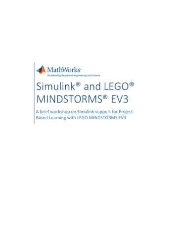
Reading the Joystick Signals Accelerometerrotate left limit - 127The joystick and accelerometer limit returnvalues are 127 and -127 as shown in thefigure. The buttons have a return value of 0when pressed and 1 when released.4 Analog Signals4 Digital Signals4 Accelerometer Signals 127 127 127 127 127 127 Accelerometerrotate forward limit 127 127X Axis Accelerometerrotate back limit 127 127Y Axis Accelerometerrotate right limit 127September 20th, 2014Copyright 2010 BEST Robotics, Inc. All rights reserved.15
September 20th, 2014Copyright 2010 BEST Robotics, Inc. All rights reserved.16
Start building your robot Click and drag one Game pad button and one onegame pad joystick.September 20th, 2014Bison BEST17
robot building Make four copies of gamepad joystick and fourcopies of gamepad buttonsSeptember 20th, 2014Bison BEST18
Actuating Motors and ServosSeptember 20th, 2014Copyright 2010 BEST Robotics, Inc. All rights reserved.19
Actuator ControlsAugust 1, 2010Copyright 2010 BEST Robotics, Inc. All rights reserved.20
Add motors and ServosAugust 1, 2010Copyright 2010 BEST Robotics, Inc. All rights reserved.21
Other Model FunctionsAugust 1, 2010Copyright 2010 BEST Robotics, Inc. All rights reserved.22
Contents of the Utilities moduleSeptember 20th, 2014Bison BEST23
Motors Drag the Arcade module into your model. Connect two motorsand two analog joysticks as Drag the two digital inputs (to serve as limit switches) and oneLimit switch control block in the model. Connect the motor, limitswitch and joystickSeptember 20th, 2014Bison BEST24
Bring as Many Functions asNeeded, and ConnectSeptember 20, 2014Copyright 2010 BEST Robotics, Inc. All rights reserved.25
Now, Set the ChannelsAugust 1, 2010Copyright 2010 BEST Robotics, Inc. All rights reserved.26
Channles for the DigitalInput Limit SwitchesSeptember 20th, 2014Bison BEST27
Working with DigitalJoysticks Analog joysticks spits numbers from -127 to 127, i.e.while digital joysticks spits only two numbers, 0 and1. Therefore, digital joystick commands are ON andOFF only, there are no intermediate values. You canhave slow and high speeds or stop the servo inbetween fully open and fully closed. When a digital joystick is connected to the servo, weneed to translate its value of 1 as 127using amultiplier Open the Mathematical tools library, and get a GAINSeptember 20th, 2014Bison BEST28
Drag the Gain icon and make as many copies as thedigital joysticks that you haveSeptember 20th, 2014Bison BEST29
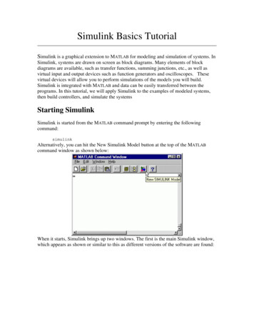
Set the multiplier Double click the gain to open its properties window Set a Gain or multiplier of 127 for all digital joysticksthat drive servos (or motors)September 20th, 2014Bison BEST30
The final modelSeptember 20th, 2014Bison BEST31
After Building the Model Save the simulink model file You may want to Simulate the model beforedownloading into your Vex Controller. Open the utilities block again (if it is closed) Pay attention to the Simulation Input, and theSimulation Output collectionsAugust 1, 2010Copyright 2010 BEST Robotics, Inc. All rights reserved.32
August 1, 2010Copyright 2010 BEST Robotics, Inc. All rights reserved.33
Simulating the Arcade Pull a variable input, a the field simulatorand a toggle. Make as mane copies as necessary Connect the variable inputs to the inputs of the joysticksConnect the toggles to the inputs of the joysticksConnect the field simulator to the two drive motorsAugust 1, 2010Copyright 2010 BEST Robotics, Inc. All rights reserved.34
Simulation ControlAugust 1, 2010Copyright 2010 BEST Robotics, Inc. All rights reserved.35
After Simulation Remove all simulation signals Save your model file Compile the model to generate C-codes andupload into Cortex microcontroller. Make sureCortex is connected August 1, 2010Choose Code- C/C Code - Build ModelCopyright 2010 BEST Robotics, Inc. All rights reserved.36
Additional ompetitions/best-robotics/September 20th, 2014Bison BEST37
Sep 20, 2014 · MATLAB Simulink Simulink is MATLAB’s graphical programming interface. Programming is accomplished by connecting various graphical icons in a specific order. Simulink graphical icons are collected in what are known as Libraries. Simulink programs are known