Transcription
40RUPackaged Air---Handling Units60 Hzwith Puronr (R---410A) RefrigerantSizes: 07 --- 16Installation, Start---Upand Service InstructionsTABLE OF CONTENTSChilled Water Coil Freeze Protection . . . . . . . . . . . 27Coil Removal . . . . . . . . . . . . . . . . . . . . . . . . . . . . . . 27SAFETY CONSIDERATIONS . . . . . . . . . . . . . . . . . . . 1Cleaning Cooling Coil . . . . . . . . . . . . . . . . . . . . . . . 27PRE-- INSTALLATION . . . . . . . . . . . . . . . . . . . . . . . . . 2Cleaning Insulation . . . . . . . . . . . . . . . . . . . . . . . . . 27Moving and Storage . . . . . . . . . . . . . . . . . . . . . . . . . . 2Replacing Filters . . . . . . . . . . . . . . . . . . . . . . . . . . . 27Rigging . . . . . . . . . . . . . . . . . . . . . . . . . . . . . . . . . . . . 2START-- UP CHECKLIST . . . . . . . . . . . . . . . . . . 39-- 40INSTALLATION . . . . . . . . . . . . . . . . . . . . . . . . . . 2–23General . . . . . . . . . . . . . . . . . . . . . . . . . . . . . . . . . . . . 2Uncrating . . . . . . . . . . . . . . . . . . . . . . . . . . . . . . . . . . 2Accessories . . . . . . . . . . . . . . . . . . . . . . . . . . . . . . . . . 2Rated Indoor Airflow (cfm) . . . . . . . . . . . . . . . . . . . 11Unit Positioning . . . . . . . . . . . . . . . . . . . . . . . . . . . . 12Unit Isolation . . . . . . . . . . . . . . . . . . . . . . . . . . . . . . 13Refrigerant and Chilled Water Piping Access . . . . . 13Refrigerant Piping . . . . . . . . . . . . . . . . . . . . . . . . . . 13Chilled Water Piping . . . . . . . . . . . . . . . . . . . . . . . . 17Condensate Drain . . . . . . . . . . . . . . . . . . . . . . . . . . . 18Fan Motors and Drives . . . . . . . . . . . . . . . . . . . . . . . 18Power Supply and Wiring . . . . . . . . . . . . . . . . . . . . 19Connecting Ductwork . . . . . . . . . . . . . . . . . . . . . . . 23Return-- Air Filters . . . . . . . . . . . . . . . . . . . . . . . . . . 23START-- UP . . . . . . . . . . . . . . . . . . . . . . . . . . . . . . . . . 24SERVICE . . . . . . . . . . . . . . . . . . . . . . . . . . . . . . . 24–38Panels . . . . . . . . . . . . . . . . . . . . . . . . . . . . . . . . . . . . 24Fan Motor Lubrication . . . . . . . . . . . . . . . . . . . . . . . 24Fan Shaft Bearings . . . . . . . . . . . . . . . . . . . . . . . . . . 25Centering Fan Wheel . . . . . . . . . . . . . . . . . . . . . . . . 25Fan Shaft Position Adjustment . . . . . . . . . . . . . . . . 25Individual Fan Wheel Adjustment . . . . . . . . . . . . . . 26Fan Belts . . . . . . . . . . . . . . . . . . . . . . . . . . . . . . . . . 26Fan Rotation . . . . . . . . . . . . . . . . . . . . . . . . . . . . . . . 26Fan Pulley Alignment . . . . . . . . . . . . . . . . . . . . . . . 26Pulley and Drive Adjustment . . . . . . . . . . . . . . . . . . 26Condensate Drains . . . . . . . . . . . . . . . . . . . . . . . . . . 26SAFETY CONSIDERATIONSImproper installation, adjustment, alteration, service,maintenance, or use can cause explosion, fire, electricalshock or other conditions which may cause personalinjury or property damage. Consult a qualified installer,service agency, or your distributor or branch forinformation or assistance. The qualified installer oragency must use factory-- authorized kits or accessorieswhen modifying this product. Refer to the individualinstructions packageFollow all safety codes. Wear safety glasses and workgloves. Use quenching cloths for brazing operations andhave a fire extinguisher available. Read these instructionsthoroughly and follow all warnings or cautions attached tothe unit. Consult local building codes and appropriatenational electrical codes (in USA, ANSI/NFPA70,National Electrical Code (NEC); in Canada, CSA C22.1)for special requirements.It is important to recognize safety information. This is the. When you see this symbol on thesafety-- alert symbolunit and in instructions or manuals, be alert to thepotential for personal injury.Understand the signal words DANGER, WARNING,CAUTION, and NOTE. These words are used with thesafety-- alert symbol. DANGER identifies the most serioushazards which will result in severe personal injury ordeath. WARNING signifies hazards which could result inpersonal injury or death. CAUTION is used to identifyunsafe practices, which may result in minor personalinjury or product and property damage. NOTE is used tohighlight suggestions which will result in enhancedinstallation, reliability, or operation.Return-- Air Filters . . . . . . . . . . . . . . . . . . . . . . . . . . 261
!PRE--INSTALLATIONWARNING1. The power supply (v, ph, and Hz) must correspond tothat specified on unit rating plate.2. The electrical supply provided by the utility must besufficient to handle load imposed by this unit.3. Refer to Installation, General section (page 2) andFig. 1 and Fig. 2 for locations of electrical inlets,condensate drain, duct connections, and requiredclearances before setting unit in place.4. This installation must conform with local buildingcodes and with the NEC (National Electrical Code) orANSI (American National Standards Institute)/NFPA(National Fire Protection Association) latest revision.Refer to provincial and local plumbing or wastewatercodes and other applicable local codes.ELECTRICAL SHOCK HAZARDFailure to follow this warning could cause personalinjury or death.Before performing service or maintenance operationson unit, turn off main power switch to unit and installlock(s) and lockout tag(s). Ensure electrical service torooftop unit agrees with voltage and amperage listedon the unit rating plate. Unit may have more than onepower switch.40RU!WARNINGUNIT OPERATION AND SAFETY HAZARDFailure to follow this warning could cause in personalinjury,death and/or equipment damage.PuronR (R-- 410A) refrigerant systems operate athigher pressures than standard R-- 22 systems. Do notuse R-- 22 service equipment or components on Puronrefrigerant equipment.!WARNINGPERSONAL INJURY AND ENVIRONMENTALHAZARDFailure to follow this warning could cause in personalinjury or death.Relieve pressure and recover all refrigerant beforesystem repair or final unit disposal.Wear safety glasses and gloves when handlingrefrigerants. Keep torches and other ignition sourcesaway from refrigerants and oils.Moving and Storage - To transfer unit from truck tostorage site, use a fork truck. Do not stack units more than2 high during storage. If unit is to be stored for more than2 weeks before installation, choose a level, dry storagesite free from vibration. Do not remove plastic wrap orskid from unit until final installation.Rigging - All 40RU Series units can be rigged by usingthe shipping skid. Units are shipped fully assembled. Donot remove shipping skids or protective covering until unitis ready for final placement; damage to bottom panels canresult. Use slings and spreader bars as applicable to liftunit.INSTALLATIONGeneral - Allow the following clearances for serviceaccess and airflow:S Rear: 3 ft (914 mm) [21/2 ft (762 mm) with electric heataccessory]S Front: 21/2 ft (762 mm)S Right Side: 31/2 ft (1067 mm)!CAUTIONCUT HAZARDFailure to follow this caution may result in personalinjury.Sheet metal parts may have sharp edges or burrs. Usecare and wear appropriate protective clothing, safetyglasses and gloves when handling parts and servicing40RU units.!CAUTIONUNIT OPERATION HAZARDFailure to follow this caution could cause equipmentdamage.Ensure voltage listed on unit data plate agrees withelectrical supply provided for the unit.S Left Side: 21/2 ft (762 mm)For units equipped with an economizer, refer to theaccessory installation instructions for additional clearancerequirements. Be sure floor, wall, or ceiling can supportunit weight (Tables 1A – 1F). See Fig. 1 and Fig. 2 fordimensions.Uncrating - Move unit as near as possible to finallocation before removing shipping skid.Remove metal banding, top skid, and plastic wrap.Examine unit for shipping damage. If shipping damage isevident, file claim with transportation agency. Removebase skid just prior to actual installation.Check nameplate information against available powersupply and model number description in Fig. 3.NOTE: Be sure to remove the styrofoam shipping padfrom the thermostatic expansion valve (TXV). Verify thatit has been removed. See Fig. 4.Accessories - Refer to instructions shipped with eachaccessory for specific information.2
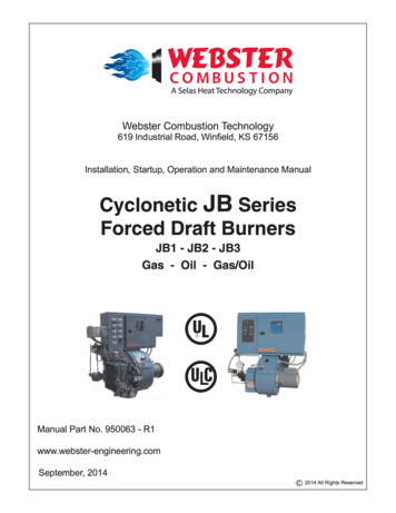
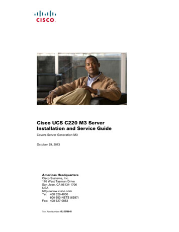
Table 1A — 40RUA Physical Data, English — Cooling UnitsUNIT 40RUA*0708121416671/210121/215Base Unit with TXV399404425695713Plenum175175175225225Qty.Diam. (in.)1.151.151.152.152.15Nominal Airflow (cfm)240030004000500060001800--- 30002250--- 37503000--- 50003750--- 62504500--- 0 and -60 and 25172517251725R--- 410AR--- 410AR--- 410AR--- 410AR--- 410A3.03.01.5/1.52.0/2.02.5/2.5NOMINAL CAPACITY (Tons)OPERATING WEIGHT (lb)FANSAirflow Range (cfm)Nominal Motor Hp (Standard Motor)REFRIGERANTOperating charge (lb) (approx per circuit){DIRECT ---EXPANSION COILEnhanced Copper Tubes, Aluminum Sine--- Wave FinsMax Working Pressure (psig)650650650650650Face Area (sq ft)6.678.3310.013.2517.67No. of Splits11222No. of Circuits per Split121591216Split /82.11/82.11/8PIPING CONNECTIONS,Quantity.Size (in.)DX Coil — Suction (ODF)DX Coil — Liquid Refrigerant (ODF)Steam Coil, In (MPT)Steam Coil, Out (MPT)Hot Water Coil, In (MPT)Hot Water Coil, Out 21.11/21.11/2Condensate (PVC)FILTERS2.5/81.21/21 11/21.11/21.11/21.15/2.5/81.21/21 11/22.5/81 11/21.21.21.21.21.21/218 ODM / 1 /4 IDFThrowaway — Factory Supplied4.16 x 24 x 24.16 x 24 x 24.16 x 24 x 24.16 x 20 x 24.16 x 24 x 24.16 x 20 x 24.16 x 24 x 2Either SideEither SideEither SideEither SideEither SideMax Working Pressure (psig at 260 F)Total Face Area (sq 91.91.91.101.10Quantity.Size (in.)Access LocationSTEAM COIL}HOT WATERCOIL}Max Working Pressure (psig)150150150150150Total Face Area (sq ins/in.Water VolumeLEGENDDX — Direct ExpansionTXV — Thermostatic Expansion Valve{Units are shipped without refrigerant charge.}Field installed accessory only.340RUMotor Speed (rpm)
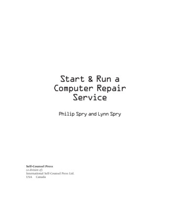
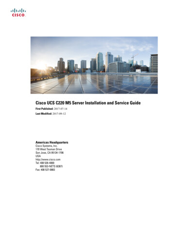
Table 1B — 40RUA Physical Data, SI — Cooling UnitsUNIT 40RUA*0708121416NOMINAL CAPACITY (kW)2126354352Base Unit with 12.3812.38111331604188823602831850--- 14161203--- 20061416--- 23601770--- 29492124--- -60 and /230---3---60 and .828.828.828.8R--- 410AR--- 410AR--- 410AR--- 410AR--- 410A1.361.360.68/0.680.90/0.901.13/1.13OPERATING WEIGHT (kg)FANSQty.Diam. (mm)Nominal Airflow (L/s)Airflow Range (L/s)Nominal Motor kW (Standard Motor)40RUMotor Speed (r/s)REFRIGERANTOperating charge (kg) (approx per circuit){DIRECT ---EXPANSION COILEnhanced Copper Tubes, Aluminum Sine--- Wave FinsMax Working Pressure (kPag)44814481448144814481Face Area (sq m)0.620.770.930.931.64No. of Splits11222No. of Circuits per Split121591216Split .11/82.11/82.11/8PIPING CONNECTIONS,Quantity.Size (in.)DX Coil — Suction (ODF)DX Coil — Liquid Refrigerant (ODF)Steam Coil, In (MPT)Steam Coil, Out (MPT)Hot Water Coil, In (MPT)Hot Water Coil, Out 21.11/21.11/2Condensate /21.11/22.5/81.21/21.11/21.21.21.21.21.15/8 ODM / 11/4 IDFThrowaway — Factory SuppliedQuantity.Size (mm)Access Location4.406 x 610 x 514.406 x 508 x 514.406 x 610 x 51Either SideEither SideSTEAM COIL}Max Working Pressure (kPag at 126 C)138138138138138Total Face Area (sq m)0.620.620.621.241.241.3551.3551.3551.3941.394Max Working Pressure (kPag)10341034103410341034Total Face Area (sq s.Fins/mHOT WATERCOIL}Rows.Fins/mWater 0520.052LEGENDDX — Direct ExpansionTXV — Thermostatic Expansion Valve{Units are shipped without refrigerant charge.}Field installed accessory only.4
Table 1C — 40RUQ Physical Data, English — Heat Pump UnitsUNIT 40RUQ*0707T0812166671/21015Base Unit with TXV381381385427713Plenum175175175175225Qty.Diam. (in.)1.151.151.151.152.15Nominal Airflow (cfm)240024003000400060001800--- 30001800--- 30002250--- 37503000--- 50004500--- 0 and --60 and 25172517251725R--- 410AR--- 410AR--- 410AR--- 410AR--- 410A3.03.03.02.0/2.03.0/3.0NOMINAL CAPACITY (Tons)OPERATING WEIGHT (lb)FANSAirflow Range (cfm)Nominal Motor Hp (Standard Motor)REFRIGERANTOperating charge (lb) (approx per circuit){DIRECT ---EXPANSION COILEnhanced Copper Tubes, Aluminum Sine--- Wave FinsMax Working Pressure (psig)650650650650650Face Area (sq ft)8.338.338.3310.016.56No. of Splits11122No. of Circuits per Split151212910Split .11/21.11/21.2PIPING CONNECTIONS,Quantity.Size (in.)DX Coil
codes and other applicable local codes. Moving and Storage --To transfer unit from truck to storage site, use a fork truck. Do not stack units more than 2 high during storage. If unit is to be stored for more than 2 weeks before installation, choose a level, dry storage site free from vibration. Do not remove plastic wrap or skid from unit until final installation. Rigging --All 40RU Series .