Transcription
W 8ST RCOMBUSTIONA Selas Heat Technology CompanyWebster Combustion Technology619 Industrial Road, Winfield, KS 67156Installation, Startup, Operation and Maintenance ManualCyclonetic J B SeriesForced Draft BurnersJB1-JB2-JB3Gas - Oil - Gas/OilManual Part No. 950063 - R1www.webster-engineering.comSeptember, 2014 2014 All Rights Reserved
SAFETY PRECAUTIONSGood safety practices must be used when working on burner equipment. The potential energy in the electrical supply,fuel and related equipment must be handled with extreme care to prevent equipment failures, injuries and potentialdeath.Throughout this manual, the following symbols are used to identify potential problems.WARNINGThis indicates a potential hazardous situation, which if not avoided, could result in personal injury or death.CAUTIONThis indicates a potentially hazardous situation, which if not avoided, could result in damage to the equipment.The following general safety precautions apply to all equipment work.WARNINGIF YOU SMELL GAS, OPEN WINDOW, EXTINGUISH ANY OPEN FLAMES, STAY AWAY FROM ELECTRICALSWITCHES, EVACUATE THE BUILDING AND IMMEDIATELY CALL THE GAS COMPANY.IN ACCORDANCE WITH OSHA STANDARDS, ALL EQUIPMENT, MACHINES AND PROCESSES SHALL BELOCKED OUT PRIOR TO SERVICING.IF THIS EQUIPMENT IS NOT INSTALLED, OPERATED AND MAINTAINED IN ACCORDANCE WITH THE MANUFACTURERS INSTRUCTIONS, THIS PRODUCT COULD EXPOSE YOU TO SUBSTANCES IN FUEL OR FROMFUEL COMBUSTION WHICH CAN CAUSE DEATH OR SERIOUS ILLNESS AND WHICH ARE KNOWN TO THESTATE OF CALIFORNIA TO CAUSE CANCER, BIRTH DEFECTS OR OTHER REPRODUCTIVE HARM.IMPROPER SERVICING OF THIS EQUIPMENT MAY CREATE A POTENTIAL HAZARD TO EQUIPMENT ANDOPERATORS.SERVICING MUST BE DONE BY A FULLY TRAINED AND QUALIFIED PERSONNEL.BEFORE DISCONNECTING OR OPENING UP A FUEL LINE AND BEFORE CLEANING OR REPLACINGPARTS OF ANY KIND, TURN OFF THE MAIN MANUAL FUEL SHUTOFF VALVES INCLUDING THE PILOT COCK, IFAPPLICABLE. IF A MULTIPLE FUEL BURNER, SHUT OFF ALL FUELS. TURN OFF ALL ELECTRICAL DISCONNECTS TO THE BURNER AND ANY OTHER EQUIPMENT ORSYSTEMS ELECTRICALLY INTERLOCKED WITH THE BURNER.Date of StartupService Organization Information:Company NameLead TechnicianAddressPhone NumberJB ManualPage Safety Precautions
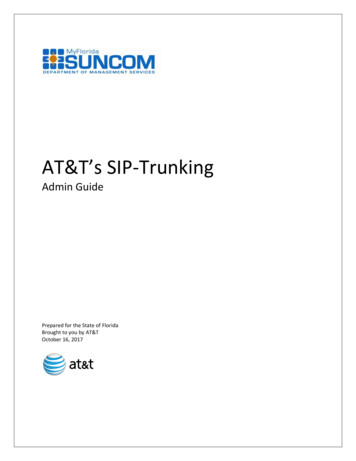
TABLE OF CONTENTSA.B.C.D.E.F.G.H.I.J.K.L.M.N.Safety Precautions . 2Introduction . 3Burner Model Number . 5JB1 Specifications . 6JB2 Specifications . 8JB3 Specifications . 10Component ldentification . 12Installation . 17Special lnstructions For Canadian lnstallations .18Burner Mounting Criteria . 19Fuel Systems . 20Initial Settings . 28Ignition Systems . 30Start-up & Operating Adjustments . 32Trouble Shooting . 42General Maintenance and Care . 45Care of The Burner During Extended Shutdown . 48Replacement Parts . 48Warranty Validation & Field Start-up Report . 48Start-Up Report . 49A. INTRODUCTIONThis manual covers the Models JB1, JB2 and JB3 CYCLONETIC burners offered by Webster Engineering & Manufacturing Co., LLC. These burners can be used in a widevariety of Cast Iron, Firebox, Firetube, Flextube and otherapplications. They can fire gas, oil and combination gasand oil with several different operating systems.similar to the nameplates shown in Figure A-1. An“X” in the model number refers to a low NOx burner,where FGR or a NOx cone is used to reduce the NOxin the combustion gases. If the burner is not a low NOxburner, there is no “X” in the model.Figure A-1 NameplateREAD AND SAVE THESE INSTRUCTIONS FOR REFERENCEWARNINGDO NOT ATTEMPT TO START, ADJUST OR MAINTAIN THIS BURNER WITHOUT PROPER TRAININGOR EXPERIENCE. FAILURE TO USE KNOWLEDGEABLE TECHNICIANS CAN RESULT IN EQUIPMENTDAMAGE, PERSONAL INJURY OR DEATH.NOTE: This manual must be readily available to all operators and maintained in legible condition.1. Nameplate InformationEach burner has a nameplate with important job details,JB ManualSERIAL NUMBERU81375A-018-06GAS INPUT RATINGOIL INPUT 16801.012100FUELThe startup and maintenance of the JB burner requires theskills of an experienced and properly trained burner technician. Inexperienced individuals should not attempt to startor adjust this burner.Every attempt has been made to accurately reflect theburner construction, however, product upgrades and special order requirements may result in differences betweenthe content of this manual and the actual equipment.These special components will be described in the information provided with the burner and should be used as thecontrolling document.MODEL NUMBERJB2C-15-RM7840L-UL-IRI#2 FUEL OILNATURAL GASHPVOLTSAMPSHERTZPHASECONTROL CIRCUIT1155.0601BURNER MOTOR2085.96031.5OIL PUMP MOTOR2084.36031/2The serial number represents the unique number for thatburner and is a critical number that will be needed for anycommunications with Webster Engineering.The input rates define the maximum and minimum inputsfor that burner, given in MBH for gas and GPH for oil. Airatomized burners show both the oil pressure and air pressure. Pressure atomized burners only list the oil pres-Page Introduction
sure. For gas firing, the gas manifold pressure is given in“in wc” which is inches of water column.The electrical ratings of the burner are given, with the voltage, current load, frequency and phase (this will either besingle or 3-phase). For motors, the motor HP is listed.2. Ratingse. Catalog cuts of the major components. These providedetails on the installation, adjustment and maintenance ofthe components used on the burner.5.Service, Parts and other InformationService and parts are available from your local WebsterRepresentative. For a list of Webster Representatives,please visit the Webster web site at:The ratings for each specific burner are given on the nameplate. The general burner ratings are given in Specification Sheets that follow this section. The maximum inputsare given, based on the type of fuel. Other conditions, likethe supply gas pressure or the combination of fuels, emission requirements and control systems may prevent theburner from reaching the lowest firing rate.www.webster-engineering.com or call 620-221-7464.3. Product OfferingThe JB burner can fire natural gas, propane and digestergas as well as all grades of light and heavy oil (#2, #4, #5and #6 oils as defined by ASTM D396).DO NOT USE GASOLINE, CRANKCASE OIL OR ANYOIL CONTAINING GASOLINE.This burner is also available as a low emission burner, andwill have model designation JBX. Several low NOx ratesare available for all gas and light oil burners, with the standard offering of 60 ppm and 30 ppm when firing naturalgas. Heavy oil is not allowed in combination with low NOx,as the high sulfur content can recirculate from the vesselthrough the burner when switched from heavy oil to gas.Low sulfur heavy oil can be used with gas FGR, when thesulfur is under ½% (the FGR is closed during oil firing).The burner can also be equipped with a NOx cone for lowNOx on gas, which does not require FGR. (See Addendum 950064).Figure A-2 lists the common variations and options available on this product. The minimum furnace conditions aregiven in Section C.4. Your Complete ManualIn addition to this manual, there are several other documents that should be considered as part of the completemanual for the burner. All of these documents are neededto support the installation and startup of the unit. Theseadditional items include:a. The wiring diagram, which shows the limits and interconnection of the burner and vessel controls.b. The gas and oil piping schematics, which show thecomponents and their relative positions in the piping train.c. The unit material list which provides an overview ofthe burner requirements and a complete bill of material,including the part numbers and description for each item.d. The flame safeguard manual provides the operating sequence for the burner management system. This will be acritical document for troubleshooting any future problems.JB ManualPage Introduction
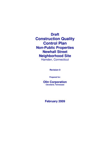
MODEL JB(X) BURNER MODEL CONFIGURATIONFIGURE A-2JBX1G -05-RM7800L-M.25-M-A-UL/CSD-1BURNER SERIESJBCODES ANDLISTINGSJB SERIESULFGR or NOx CONEUSEDXNOT USEDBLANKULcCSD-1FMIRIHEAD SIZE (INCHES)JBJBX17 1/87 1/229 1/89 1/2311 1/811 1/2NFPA-85OIL SYSTEMSPressure AtomizingFUELSGGasOOilCGas / OilAOn - OffLLow Fire StartHLow - Hi - LowMPModulation SimplexMRModulation By-PassAir or Steam AtomizationBLOWER MOTORHORSEPOWERMAAir AtomizationMSSteam s101MMaxon151 1/2202BlankAll Others(ASCO) - (std)303505757 1/210010GAS TRAIN VENDORGAS TRAIN SIZEFLAME SAFEGUARDVENDOR DESIGNATIONRM7800LHoneywellM MarkAutoFlame - mini emens.151 1/2 inches.202 inches.252 1/2 inches.303 inches.404 inchesGAS SYSTEMAOn-OffLLow Fire StartHLow-Hi-LowMModulationThe above represents the common model designations.Contact the factory for other options and special applications.JB ManualPage Identification
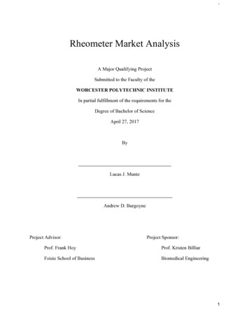
Model JB1 - Specification Data(400 - 2500 MBH Input)XXAir Flow Switch (also with oil systems using remote pump)X(2) Burner Mounted Control Panel,Switch and Indicator LightsXXFlame Safety ControlXXUltra Violet ScannerXXMotor Controller (single phasevoltage)XXDuel Fuel Burners OnlyOptionalIgnitionProven Gas Pilot IgnitionMain Manual Shutoff ValveXMain Safety Shutoff ValveXSecond Safety Shutoff ValveXMain Gas RegulatorXGas Checking ValveXHigh and Low Gas PressureSwitches (st’d over 2500 MBH)Opt.Metering Valve (modulation only)XOil Drawer Assembly with DiffuserXXPilot Solenoid Gas ValveXOil Nozzle(s)XPilot Gas Regulator & Manual ValveXIntegral Oil PumpXPilot Gas Ignition TransformerXDirect Spark Oil IgnitionXDirect Spark Oil IgnitionTransformerXOil FuelGeneralFuel Selector SwitchGasNo. 2 OilpressureatomizedMotor, Fan and Air Inlet ControlAND IMPORTANT OPTIONSSTANDARD UL EQUIPMENTAND IMPORTANT OPTIONSGas FuelGas(1) STANDARD UL EQUIPMENTFuel BurnedNo. 2 OilpressureatomizedFuel BurnedMain Safety Shutoff ValveXSecond Safety Shutoff ValveXLow Oil Pressure Switch(STD when using remote oil pump)Opt.Inverted HousingXXOil Pressure GaugeXAlternate Control CabinetPositioningXXOil Metering Valve (modulatingsystems)XRemote Control PanelXXFuture Gas Combustion Head-OPTFuel Metering CAM-NETIC IIXXOpt.1. The configuration of each unit will vary with specific job requirements such as input rating, electrical specification and special agency approvalcodes. The above chart shows those items standard to a basic burner plus a few options that may be added.2. Indicator lights are “Power On”, “Call for Heat”, ”Fuel On” and ”Flame Fail” for hard wired panels. “Alarm”, “Low Water”, “Power”, “Call forHeat”, “Ignition On”, and “Fuel On” for circuit board light panels.Model JB1 - Sizing and Application Data (contact Webster for complete r Firing CapabilityRangeGas scfh#2 Oil gphBurner Motor HPGas TrainGas OnlyHP(3) Oil orCombinationPipe SizeOil PumpMotor HP(4) Inlet PressureOn-Off, LFSModulationJB1-021.25400 / 10003.0 / 7.11/41/31”6 / 14”7 /14”IntegralJB1-031.25600 / 15004.0 / 10.71/31/21 1/4”8 / 14”9 / 14”IntegralJB1-051.25800 / 21006.0 / 14.81/21/21 1/2”7 / 14”8 / 14”IntegralJB1-071.25900 / 25007.0 / 17.83/43/41 1/2”9 / 14”11 / 14”Integral3. Larger motors may be required for single phase or 208 volts4. Contact Webster for more complete detailsThe above maximum ratings are based on 0 furnace pressure, an altitude of 1000 feet, 90oF air temperature and 60 HZ electrical supply. Usethe following corrections for higher temperatures and altitude. Capacity decreases by 17% for 50 Hertz.Capacity decreases by 4% for each 1000 feet above 1000 foot altitude.Capacity decreases by 6% f
to support the installation and startup of the unit. These additional items include: a. The wiring diagram, which shows the limits and inter-connection of the burner and vessel controls. b. The gas and oil piping schematics, which show the components and their relative positions in the piping train. c. The unit material list which provides an overview of