Transcription
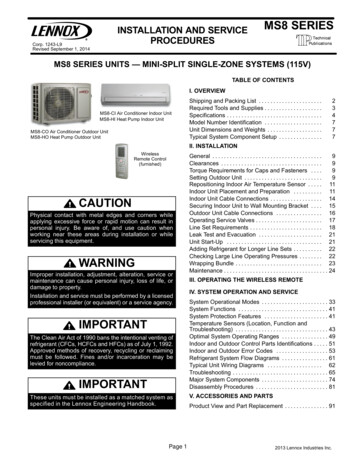
INSTALLATION AND SERVICEPROCEDURESCorp. 1243-L9Revised September 1, 2014MS8 SERIESMS8 SERIES UNITS — MINI-SPLIT SINGLE-ZONE SYSTEMS (115V)TABLE OF CONTENTSI. OVERVIEWMS8-CI Air Conditioner Indoor UnitMS8-HI Heat Pump Indoor UnitMS8-CO Air Conditioner Outdoor UnitMS8-HO Heat Pump Outdoor UnitShipping and Packing List . . . . . . . . . . . . . . . . . . . . . .Required Tools and Supplies . . . . . . . . . . . . . . . . . . . .Specifications . . . . . . . . . . . . . . . . . . . . . . . . . . . . . . . . .Model Number Identification . . . . . . . . . . . . . . . . . . . .Unit Dimensions and Weights . . . . . . . . . . . . . . . . . . .Typical System Component Setup . . . . . . . . . . . . . . .234777II. INSTALLATIONWirelessRemote Control(furnished)CAUTIONPhysical contact with metal edges and corners whileapplying excessive force or rapid motion can result inpersonal injury. Be aware of, and use caution whenworking near these areas during installation or whileservicing this equipment.WARNINGImproper installation, adjustment, alteration, service ormaintenance can cause personal injury, loss of life, ordamage to property.Installation and service must be performed by a licensedprofessional installer (or equivalent) or a service agency.IMPORTANTThe Clean Air Act of 1990 bans the intentional venting ofrefrigerant (CFCs, HCFCs and HFCs) as of July 1, 1992.Approved methods of recovery, recycling or reclaimingmust be followed. Fines and/or incarceration may belevied for noncompliance.IMPORTANTThese units must be installed as a matched system asspecified in the Lennox Engineering Handbook.Page 1General . . . . . . . . . . . . . . . . . . . . . . . . . . . . . . . . . . . . . .9Clearances . . . . . . . . . . . . . . . . . . . . . . . . . . . . . . . . . . .9Torque Requirements for Caps and Fasteners . . . .9Setting Outdoor Unit . . . . . . . . . . . . . . . . . . . . . . . . . . .9Repositioning Indoor Air Temperature Sensor . . . . . 11Indoor Unit Placement and Preparation . . . . . . . . . . 11Indoor Unit Cable Connections . . . . . . . . . . . . . . . . . . 14Securing Indoor Unit to Wall Mounting Bracket . . . . 15Outdoor Unit Cable Connections . . . . . . . . . . . . . . . . 16Operating Service Valves . . . . . . . . . . . . . . . . . . . . . . . 17Line Set Requirements . . . . . . . . . . . . . . . . . . . . . . . . . 18Leak Test and Evacuation . . . . . . . . . . . . . . . . . . . . . . 21Unit Start-Up . . . . . . . . . . . . . . . . . . . . . . . . . . . . . . . . . 21Adding Refrigerant for Longer Line Sets . . . . . . . . . . 22Checking Large Line Operating Pressures . . . . . . . . 22Wrapping Bundle . . . . . . . . . . . . . . . . . . . . . . . . . . . . . . 23Maintenance . . . . . . . . . . . . . . . . . . . . . . . . . . . . . . . . . . . . 24III. OPERATING THE WIRELESS REMOTEIV. SYSTEM OPERATION AND SERVICESystem Operational Modes . . . . . . . . . . . . . . . . . . . . . . . 33System Functions . . . . . . . . . . . . . . . . . . . . . . . . . . . . . . . 41System Protection Features . . . . . . . . . . . . . . . . . . . . . . 41Temperature Sensors (Location, Function andTroubleshooting) . . . . . . . . . . . . . . . . . . . . . . . . . . . . . . . . 43Optimal System Operating Ranges . . . . . . . . . . . . . . . . 49Indoor and Outdoor Control Parts Identifications . . . . . 51Indoor and Outdoor Error Codes . . . . . . . . . . . . . . . . . . 53Refrigerant System Flow Diagrams . . . . . . . . . . . . . . . . 61Typical Unit Wiring Diagrams . . . . . . . . . . . . . . . . . . . 62Troubleshooting . . . . . . . . . . . . . . . . . . . . . . . . . . . . . . . . . 65Major System Components . . . . . . . . . . . . . . . . . . . . . . . 74Disassembly Procedures . . . . . . . . . . . . . . . . . . . . . . . . . 81V. ACCESSORIES AND PARTSProduct View and Part Replacement . . . . . . . . . . . . . . . 912013 Lennox Industries Inc.
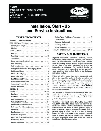
I. OVERVIEWShipping and Packing ListCheck the unit components for shipping damage. If you find any damage, immediately contact the last carrier.1 — ASSEMBLED INDOOR UNITThe assembled indoor unit will include the following items:Part PicturePart PicturePart NameName NameRemote control (1 each)1/4” flare nut (45º-degreeSAE style) for small line(1 each)Batteries (AAA)(2 each)Foam tube insulation(for condensate line at tached to indoor unit)Wall mounting bracketscrews (5 each)Wall mounting bracket(1 each)1 — ASSEMBLED OUTDOOR UNITThe assembled outdoor unit will include the following items which are located with the unit:PartsAuxiliary drainhole plugs (heatpump only)MS8C / MS8H (115V)FigureQuantity1-3PartsDrain plug(heat pump only)Page 2FigureQuantity1
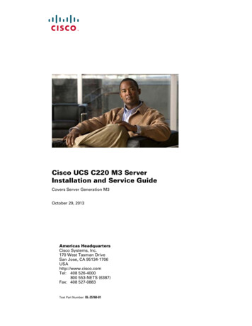
Required Tools and SuppliesINSTALLATION TOOLSTool PictureTool NameTool NameTool PictureScrew driverMultimeterElectric drillAllen wrench set(metric)Flaring tool and pipecutterMeasuring tape andknifeHole core drillRefrigerant leak detectoror a bottle of soapy waterAdjustable wrenchLevel500A 5/16” female flare to1/4” male flare adapter(order Lennox catalognumber Y0576)Micron gaugeSUPPLIESThe following field-provided supplies may be required for installation*******Line set (see table 7 for requirements)Foam insulation (line set and condensate line)UV rated protective tape (used to maintain positioning of bundle). Bundle consists of line set, condensate line and wiringbetween indoor and outdoor units.UV rated cable tiesOutdoor unit padOutdoor disconnect switch (indoor unit disconnect switch may be required by local code)Cable (4-conductor). All need to be rated either 115V and sized per NEC).NOTE — Stranded wire must be used to connect the outdoor unit to the indoor unit. The stranded wire is necessary to ensureproper system communication and operation.***Plastic wall screw anchorsExterior wall channel (optional)Wall sleeve or PVC tubing material to field fabricate a wall sleeve for line set, condensate line and wiring (utility bundle).Page 3Corp. 1143-L9
Specifications - AIR CONDITIONER SYSTEMSOUTDOOR UNITNominal Tonnage0.751MS8 CO 09LMS8 CO 12LSmall line o.d. flare1/41/4Large line o.d. flare3/83/841 11541 115Outdoor Unit Model No.Connections (in.)Ambient Temperature Operating Range F1Refrigerant (R 410A) furnishedOutdoor CoilOutdoor Fan MotorShipping Data lbs.2 lbs. 6 oz.2 lbs. 14 oz.Net face area sq. ft.3.954.08Tube diameter in.1/43/8Number of rows22Fins per inch1818Diameter in.15 5/815 5/8No. of 40Outdoor UnitELECTRICAL DATALine voltage data 60 hz 1ph2Maximum over-current protection (amps)3CompressorMinimum circuit ampacity2223Rated load amps1617.5105014500.170.174040MS8 CI 09LMS8 CI 12L1/44 Compressor Power Input (W)Outdoor Fan MotorRated load ampsOutput (W)MATCHING INDOOR UNITIndoor Unit Model No.Connections (in.)Small line o.d. flare1/4Large line o.d. et face area sq. ft.1.851.85Tube diameter in.1/41/4Indoor Blower Air Volume (cfm)Indoor Blower RPMIndoor CoilIndoor BlowerShipping Data lbs.Number of rows22Fins per inch1818Diameter x Length in.3.6 x 25.43.6 x 25.4TypeCross flowCross flow3131Line voltage data 60 hz 1ph115V115VRated Load Amps0.380.382020Indoor UnitELECTRICAL DATAOutput (W)NOTE Extremes of operating range are plus 10% and minus 5% of line voltage.1 Refrigerant charge sufficient for 15 ft. of line set.2 HACR type circuit breaker or fuse.3 Refer to National or Canadian Electrical Code manual to determine wire, fuse and disconnect size requirements.4 Rated InputMS8C / MS8H (115V)Page 4
Specifications - HEAT PUMP SYSTEMSINDOOR UNITNominal Tonnage0.751MS8 HO 09LMS8 HO 12LSmall line o.d. flare1/41/4Large line o.d. flare3/83/8Cooling41 11541 115Heating5 865 86Outdoor Unit Model No.Connections (in.)Ambient Temperature Operating Range F1Refrigerant (R 410A) furnishedOutdoor CoilOutdoor Fan MotorShipping Data lbs.2 lbs. 6 oz.2 lbs. 14 oz.Net face area sq. ft.3.954.08Tube diameter in.1/43/8Number of rows22Fins per inch1818Diameter in.15 5/815 5/8No. of 3540Outdoor UnitELECTRICAL DATALine voltage data 60 hz 1ph2Max. Over-current protection (amps)3CompressorMinimum circuit ampacity2223Rated load amps1617.56001200Rated load amps0.170.1740404 Compressor Power Input (W)Outdoor Fan MotorOutput (W)MATCHING INDOOR UNITIndoor Unit Model No.Connections (in.)Indoor Blower Air Volume (cfm)Indoor Blower RPM (Cooling/Heating)Indoor CoilIndoor BlowerShipping Data lbs.MS8 HI 09LMS8 HI 12LSmall line o.d. flare1/41/4Large line o.d. dium920/1100900/980Low730/950730/920Net face area sq. ft.1.851.85Tube diameter in.1/41/4Number of rows22Fins per inch1818Diameter x Length in.3.6 x 25.43.6 x 25.4TypeCross flowCross flow3737Line voltage data 60 hz 1ph115V115VRated Load Amps0.380.382020Indoor UnitELECTRICAL DATAOutput (W)NOTE Extremes of operating range are plus 10% and minus 5% of line voltage.1 Refrigerant charge sufficient for 15 ft. of line set.2 HACR type circuit breaker or fuse.3 Refer to National or Canadian Electrical Code manual to determine wire, fuse and disconnect size requirements.4 Rated InputPage 5Corp. 1143-L9
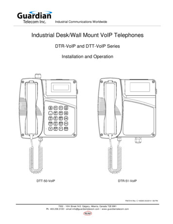
Model Number IdentificationMS8 CI 091AMinor RevisionSeries TypeMS Mini-SplitNumber of Zones1 single zoneSeriesUnit TypeCI Air Conditioner Indoor UnitHI Heat Pump Indoor UnitCO Air Conditioner Outdoor UnitHO Heat Pump Outdoor UnitMS8C / MS8H (115V)LVoltageL 115V-1phase-60hzCapacity - BTUH09 9,00012 12,000Page 6
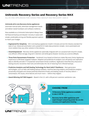
Model Number IdentificationMS8 P 09CI1AMinor RevisionSeries TypeMS Mini-SplitNumber of Zones1 single zoneSeriesUnit TypeCI Air Conditioner Indoor UnitHI Heat Pump Indoor UnitCO Air Conditioner Outdoor UnitHO Heat Pump Outdoor UnitVoltageL 115V-1phase-60hzCapacity - BTUH09 9,00012 12,000Unit Dimensions - inches (mm) and WeightsINDOOR UNITCCBLINE SET, CONDENSATEDRAIN AND ELECTRICALCONNECTIONSATABLE 1. INDOOR UNIT DIMENSIONS — INCHESModel Size-09 and -12A33-3/8B10-7/8C7BELECTRICAL CONNECTIONS (UNDER COVER)ALINE SET CONNECTIONS(COVER REMOVED)LINE SET COVERCTABLE 2. OUTDOOR UNIT DIMENSIONS — INCHESModel Size-09 and -012A21-1/4B30Page 7C12-5/8Corp. 1143-L9
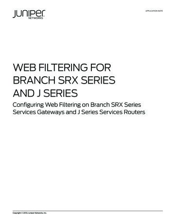
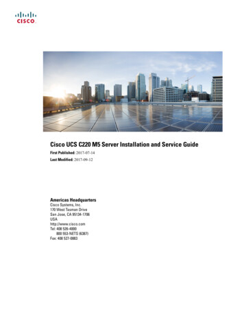
Typical System Component SetupTYPICAL COMPONENT SETUPERETURN AIRGKBLINDOOR UNITTAPEHDDISPLAYINDICATORSCOOLDCREFRIGERANT LINE SET, CONDENSATE LINEAND INDOOR / OUTDOOR CABLEFIMPORTANT - The refrigerantmetering device for this system islocated in the outdoor unit. Thismakes it necessary to insulatethe refrigerant lines individually toprevent sweating.SUPPLY AIRDRYAFANWIRELESS REMOTECONTROLHEATRUNOUTDOOR UNITTERMINAL BLOCKTEMPERATURE SETTING,INDOOR AMBIENT TEMPERATUREOR ERROR CODENOTE — temperature can bedisplayed in either Fahrenheit orCelsius.OUTDOOR UNIT (AIRCONDITIONER OR HEATPUMP)AIR INJA.B.C.D.E.F.G.H.I.J.K.L.Remote controlFront panelFiltersGuide louver with displayLine set (wrapped in foam insulation)UV-rated tape (field-provided)Wiring (field-provided)Condensate drain line (field-provided)(wrapped in foam insulation). Recommendinstallation of a vent when making longhorizontal runs on condensate line.3-way service valveAccess cover for power and control wiringconnectionsIndoor unit wiring connections (underaccess plate)Communication cable (30 kBtu systemonly)TO INDOORUNITHIAIR OUT2-WAY SHUT-OFF VALVE3-WAY SERVICE VALVE(FLARE CONNECTION)FIGURE 1MS8C / MS8H (115V)Page 8TO POWERSUPPLY
II. INSTALLATIONIMPORTANT INSTALLER INFORMATION* Confirm proper slope and routing of condensate lines to ensure moisture is drained away from the indoor unit (seeprocedure starting on page )* Confirm proper insulating, taping and bundling of refrigeration lines, main power lines and drain line (see procedurestarting on pages 23).TABLE 3MINIMUM SYSTEM CLEARANCESGeneralThe MS8 air conditioners and heat pumps are matched withan indoor evaporator unit to create a ductless system thatuses HFC-410A Clearance between unit and ceiling.6 in. (152 mm)BClearance between unit and floor.6 ft.(1829 mm)C/DCAUTIONIn order to avoid injury, take proper precaution when liftingheavy objects.6 in. (152 mm)Clearance above unit.2 ft. (610 mm)FClearance between air inlet andstructure.12 in. (305 mm)GHSYSTEM CLEARANCESRefer to figure 2 for mandatory installation clearancerequirements.MINIMUM INSTALLATION CLEARANCESClearance to the right and left of unit.EClearance between unit andstructuresI12 in. (305 mm)4 ft. (1219 mm)12 in. (305 mm)Torque Requirements for Caps and FastenersWhen servicing or repairing HVAC components, ensure thefasteners are appropriately tightened. Table 4 providestorque values for fasteners.IMPORTANTAOnly use Allen wrenches of sufficient hardness (50Rc Rockwell Harness Scale minimum). Fully insert thewrench into the valve stem recess.Service valve stems are factory-torqued (from 9 ft-lbs forsmall valves, to 25 ft-lbs for large valves) to preventrefrigerant loss during shipping and handling. Using anAllen wrench rated at less than 50Rc risks rounding orbreaking off the wrench, or stripping the valve stemrecess.See the Lennox Service and Application Notes #C-08-1for further details and information.CDBTABLE 4TORQUE REQUIREMENTSINSTALL UNIT AWAYFROM WINDOWSRecommended TorqueEUnited StatesCustomarySystem*Metric(Newton Meter)8 ft.- lb.11Sheet metal screws16 in.- lb.2Machine screws #10PartsFService valve capGIHFIGURE 227 in.- lb.3Compressor bolts7 ft.- lb.10Gauge port seal cap8 ft.- lb.11*The United States customary system (also called American system) is asystem of measurement commonly used in the United States. This systemis based on the British Imperial System.Page 9Corp. 1143-L9
Setting Outdoor UnitNOTICEOUTDOOR UNIT POSITIONING CONSIDERATIONS(AIR CONDITIONER OR HEAT PUMP)Consider the following when positioning the unit:*Some localities are
Page 1 2013 Lennox Industries Inc. Corp. 1243-L9 Revised September 1, 2014 INSTALLATION AND SERVICE MS8 SERIES PROCEDURES MS8 SERIES UNITS — MINI-SPLIT SINGLE-ZONE SYSTEMS (115V) MS8-CO Air Conditioner Outdoor Unit MS8-HO Heat Pump Outdoor Unit MS8-CI Air Conditioner Indoor Unit MS8-HI Heat Pump Indoor Unit Wireless Remote Control (furnished)