Transcription
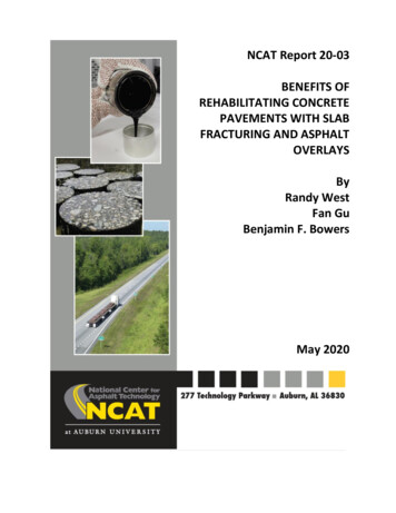
NCAT Report 20-03BENEFITS OFREHABILITATING CONCRETEPAVEMENTS WITH SLABFRACTURING AND ASPHALTOVERLAYSByRandy WestFan GuBenjamin F. BowersMay 2020
Benefits of Rehabilitating Concrete Pavements with Slab Fracturing and Asphalt OverlaysNCAT Report 20-03ByDr. Randy West, P.E.Director and Research ProfessorNational Center for Asphalt TechnologyDr. Fan Gu, P.E.Assistant Research ProfessorNational Center for Asphalt TechnologyDr. Benjamin F. Bowers, P.E.Assistant ProfessorAuburn UniversitySponsored byNational Asphalt Pavement AssociationMay 2020ii
ACKNOWLEDGEMENTSThe authors wish to thank the National Asphalt Pavement Association and State AsphaltPavement Associations for sponsoring this research project and for providing technical reviewof this document. The authors also gratefully acknowledge the following individuals for theirassistance in the case studies: Gary DeWitt, Bob Rothwell, Barry Paye, Ryan Luck, and PeterKemp. Finally, the authors would like to appreciate the following members and friends of theNCAT Applications Steering Committee for their review of this technical report: Cheng Ling,Charles Mills, Derek Nener-Plante, Matt Shinners, Mike Skinner, Christopher Wagner, and JasonWielinski.DISCLAIMERThe contents of this report reflect the views of the authors who are responsible for the factsand accuracy of the data presented herein. The contents do not necessarily reflect the officialviews or policies of the sponsoring agency, the National Center for Asphalt Technology orAuburn University. This report does not constitute a standard, specification or regulation.Comments contained in this paper related to specific testing equipment and materials shouldnot be considered an endorsement of any commercial product or service; no such endorsementis intended or implied.iii
TABLE OF CONTENTSList of Acronyms . 51 Introduction . 62 Research Objective and Scope . 63 Literature Review . 73.1Slab-Fracturing Techniques . 73.2Evaluation of Fractured PCC Slab Systems . 83.3Asphalt Overlay Mix Design . 103.4Asphalt Overlay Thickness Design . 124 National Survey of Concrete Pavement Rehabilitation . 145 LTPP Data Analysis . 225.1LTPP SPS-6 Data Assembly . 225.2Effects of PCC Treatments on Pavement Performance . 255.3Backcalculated Moduli of Fractured PCC Slabs . 305.4Effects of Design Factors on Transverse Cracking Performance . 346 Case Studies of Concrete Pavement Rehabilitation Projects . 356.1Wyoming Case . 356.2Colorado Case. 387 Summary and Conclusions . 39References . 41Appendix: Survey Questions . 45iv
LIST OF ACRONYMSAAIP: Average Annual Incremental PerformanceAASHTO: American Association of State Highway and Transportation OfficialsaFS: Fractured Slab Structural Layer CoefficientANOVA: Analysis of VarianceB&S: Break and SeatC&S: Crack and SeatCDOT: Colorado Department of TransportationCRCP: Continuously Reinforced Concrete PavementDF: Dry-FreezeEAC: Modulus of Asphalt Overlay, Unit: ksiEcr: Critical Fractured Slab Modulus, Unit: ksiEPCC: Modulus of Fractured PCC Slab, Unit: ksiESAL: Equivalent Single Axle LoadFHWA: Federal Highway AdministrationFI: Freezing Index, Unit: C degree-daysFWD: Falling Weight DeflectometerHSD: Honestly Significant DifferenceIRI: International Roughness Index, Unit: inch/mileIS: Information SeriesJPCP: Jointed Plain Concrete PavementJRCP: Jointed Reinforced Concrete PavementLTPP: Long-Term Pavement PerformanceMRI: Mean Roughness Index, Unit: inch/mileNAPA: National Asphalt Pavement AssociationPCC: Portland Cement ConcretePSI: Present Serviceability IndexSAMI: Stress-Absorbing Membrane InterlayerSAPA: State Asphalt Pavement AssociationSBS: Styrene-Butadiene-StyreneSMA: Stone Matrix AsphaltSPS: Specific Pavement StudiesTAC: Thickness of Asphalt Overlay, Unit: inchTPCC: Thickness of Fractured PCC Slab, Unit: inchWF: Wet-FreezeWNF: Wet-No FreezeWAAP: Weighted Annual Average Performance5
1INTRODUCTIONThe benefits of using asphalt overlays for rehabilitation of Portland cement concrete (PCC)pavements are grounded in economics and long-term performance. The Federal HighwayAdministration (FHWA) reports that the U.S. has 108,603 lane miles of composite pavements(PCC overlaid with asphalt), which is nearly double the lane miles of PCC-surfaced pavements(FHWA 2015). That means that nearly two-thirds of the concrete pavements in the U.S. havebeen overlaid with asphalt. However, a persistent problem with asphalt overlays on PCCpavements is reflective cracking of joints and cracks through the asphalt overlays over time.Ultimately, reflective cracking leads to a shortened performance life of the overlay. Rather thanremoving the concrete, which can be costly to the owner agency and increase delay times forthe travelling public, slab-fracturing techniques can be used prior to placement of an asphaltoverlay to significantly reduce stress concentrations at concrete joints and cracks. Slabfracturing techniques include three methods: crack and seat (C&S) for PCC without steelreinforcement, break and seat (B&S) for PCC with steel reinforcement, and rubblization for anytype of concrete pavement. C&S is intended to reduce the effective slab length of PCCpavements by producing tight surface cracks. B&S is similar but typically requires greaterfracturing effort. The rubblization process typically fractures slabs into fragments with anominal size of 4 to 8 inches (PCS, 1994). Since the existing pavement remains in-place, thereare no hauling or disposal costs, resulting in substantial cost savings for state agencies (Buncheret al., 2008).In 1994, the National Asphalt Pavement Association (NAPA) released Information Series (IS)-117Guidelines for Use of Asphalt Overlays to Rehabilitate PCC Pavements. This document describesslab-fracturing processes and equipment and provides a procedure, based on the 1993 AASHTOpavement design guide, for determining the thickness of asphalt overlays placed over fracturedPCC slabs (PCS, 1994). Since its publication, many states have begun to move toward themechanistic-empirical based AASHTOWare Pavement-ME design software. Additionally,fractured slab techniques have continued to advance, with new processes and equipmenthaving been successfully used in the rehabilitation of PCC pavements. Consequently, it is timeto consolidate current information, guidance, and successful case studies on rehabilitating PCCpavements with asphalt overlays. A comprehensive synthesis of the state-of-the-practice andguidance for these slab-fracturing methods is needed to promote these methods to agencies,road owners, designers, and contractors.2RESEARCH OBJECTIVE AND SCOPEThe primary objective of this project was to synthesize both the historical and most recentexperiences with C&S, B&S, and rubblization methods for the rehabilitation of PCC pavementswith asphalt overlays. These slab-fracturing methods were also compared to alternativeconcrete rehabilitation treatments such as partial- or full-depth patching, overlays with sawedand sealed joints, geosynthetic interlayers with overlays, and stress-absorbing membraneinterlayer with overlays. An extensive literature review was performed, a comprehensive surveyof key stakeholders was conducted, and a series of case studies were documented, with thegoal of informing agencies and industry of the most effective concrete pavement rehabilitation6
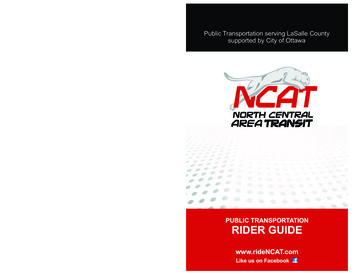
methods. Additionally, a Phase II project framework was designed and proposed to update andaddress NAPA’s guidelines for slab fracturing and asphalt overlays.33.1LITERATURE REVIEWSlab-Fracturing TechniquesThe concept of slab fracturing is to spread out the vertical and horizontal movements at jointsand cracks in concrete slabs to reduce the concentration of stresses transferred to the asphaltoverlay. Slab-fracturing techniques, including C&S, B&S, and rubblization, have been widelyrecognized as being effective in mitigating reflective cracking distresses.C&S and B&S minimize the movement of concrete slabs by reducing the effective slab lengthand seating the broken slab pieces (Freeman, 2002). Both techniques utilize pile drivers,guillotine hammers, whip hammers, or impact hammers to crack the concrete slabs followed bya heavy pneumatic roller to seat the cracked or broken pieces onto the base. Walker (2019)suggested that a test section should be used to establish the fracturing effort of the equipmentwith a test pit to verify effectiveness. Two roller passes should be required for seating.Excessive rolling might reduce interlock of the slab pieces. The only distinction between B&Sand C&S is that C&S is used on jointed plain concrete pavement (JPCP) and B&S is applied tojointed reinforced concrete pavement (JRCP). Figure 1 shows typical fractured PCC slabs usingC&S and B&S methods.Figure 1. Typical Fractured PCC using C&S (left) and B&S (right) Methods (Antigo, 2019)Rubblization eliminates the movement of old concrete pavement by fragmenting the slabs into4 to 8 inch pieces, which results in a quasi-unbound aggregate base (PCS, 1994). Two types ofequipment, multiple-head breakers and resonant pavement breakers, are typically used forrubblization. The multiple-head breaker rubblizes the slabs using a series of drop hammers. Thebreaking energy is dependent upon the lift height selected, the impact frequency, and thespeed of operation (Antigo, 2018). The resonant breaker uses a resonant beam generating highfrequency and low amplitude impacts to fracture concrete pavement. The breaking principle is7
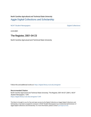
that the high-frequency, low-amplitude resonant energy delivered to the concrete slab resultsin failure along a shear plane at a 45-degree angle (Fitts, 2006).Regarding the degree of slab fracturing, NAPA IS-117 recommends that the maximum crackspacing (or resulting fragment size) be less than 30 inches for C&S projects and less than 12 to18 inches for B&S projects and that the nominal maximum fragment size be limited to 8 to 12inches for rubblization projects. In general, rubblization can meet the specified fragment sizeonly when the base and subgrade provide adequate support. If the underlying support is poor,rubblization will yield inadequate support for the asphalt overlay (Antigo, 2014). In the 2000s,Antigo developed a modified rubblization technique that employs less fracture energy toproduce a stiffer rubblized concrete layer to support construction operations and asphaltoverlays while still effectively eliminating reflective cracking (Buncher et al., 2008). Theyspecified that the maximum particle size should be less than 12 inches at the surface and lessthan 15 inches at the bottom of the slab, which differs from the recommended maximum sizeof 12 inches in IS-117 (Antigo, 2015). Figure 2 shows typical fractured PCC slabs usingrubblization and modified rubblization methods.a. Rubblizationb. Modified RubblizationFigure 2. Comparison of Full Rubblization and Modified Rubblization (Antigo, 2014)3.2Evaluation of Fractured PCC Slab SystemsIS-117 outlined field surveys on over 400 PCC rehabilitation projects with a focus on pavementcondition as well as falling weight deflectometer (FWD) results (PCS, 1994). According to thissurvey, the typical modulus values for C&S slabs was 200-800 ksi, for B&S slabs it was 600-1700ksi, and for rubblized concrete the moduli ranged from 250-750 ksi. A maximum thresholdvalue of 1000 ksi was recommended for the critical fractured slab modulus (Ecr) to eliminatereflection cracking. However, a minimum value for Ecr to ensure that fractured slabs provideadequate support for asphalt overlay was not provided. Recent FWD analyses typically reportmoduli for rubblized concrete layers in the range of 50 to 100 ksi, which is much less than theoriginal IS-117 survey results (Antigo, 2014). Therefore, further assessments of the Ecrthreshold values are needed to determine if the provisional values are valid.To assess the performance of different PCC rehabilitation treatments, the Long-Term PavementPerformance (LTPP) program Specific Pavement Studies (SPS)-6 experiment was initiated,including 14 construction projects distributed among three climatic regions (wet-freeze [WF],8
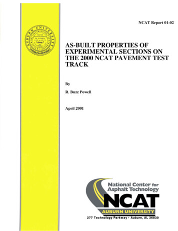
wet-no freeze [WNF], and dry-freeze [DF]). Figure 3 shows a map of LTPP SPS-6 projects. Thesections with green indicate that they are still under evaluation by LTPP, but those with red areno longer monitored. Hall et al. (2002, 2003) conducted an LTPP data analysis of theexperiment to quantify the effectiveness of rehabilitation treatments based on changes inperformance (international roughness index [IRI], rut depth, and percent cracking area) beforeand after treatments. In that study, the percent cracking area was calculated by combining thepercent area of alligator cracking and block cracking of all severities, but it did not includetransverse cracking. Excluding transverse cracking, presumed to be largely associated withreflection cracking, is considered to be a significant oversight of those studies since minimizingreflection cracking is the primary objective of slab fracturing methods. Ambroz and Darter(2005) further investigated the SPS-6 experiment and found that the data availability andcompleteness were good overall. They suggested performing site-by-site analyses to determinethe effects of design factors and treatment methods on the long-term performance ofrehabilitated pavements.Figure 3. Map of LTPP SPS-6 SectionsTo evaluate the effects of design factors, Witczak and Rada (1992) identified 454 field projectsthat utilized slab-fracturing techniques. They found that fractured slab modulus backcalculatedfrom the FWD test correlated well with crack spacing, which was critical for minimizingreflective cracking distress. They also developed predictive equations to estimate the change inpavement condition index of rehabilitated pavements over time, which included annualaverage precipitation, annual average air temperature, subgrade modulus, and crackingspacing. Rahim et al. (2013) predicted the performance of cracked, seated, and asphalt-overlaidconcrete pavement using service time, traffic volume, and thicknesses of the asphalt overlayand the existing PCC. Marshall (1999) and Ceylan et al. (2008) considered rubblized PCC as ahigh-quality granular material and suggested using mechanistic-empirical pavement design topredict the long-term performance of rehabilitated pavements.To quantify the benefits of rehabilitation treatments, the previous studies mainly focused onproject-level or local-level analyses. Bemanian and Sebaaly (1999) analysed four-yearperformance data of C&S and rubblization sections in I-80 in Nevada. The as-constructed9
asphalt overlay thickness of the C&S section was 6.7 inches, and that of the rubblization sectionwas 8 inches. They reported that both the C&S and rubblization sections performed equally wellin terms of ride quality and rut depth, but the 1.4-inch thinner overlay on the C&S sectionlowered the unit construction cost by approximately 68,780/mile compared to therubblization section. Morian et al. (2003) evaluated the 10-year performance of PennsylvaniaSPS-6 sections. They concluded that rubblization was the most cost-effective rehabilitationtreatment, following by C&S or B&S with an 8-inch asphalt overlay. Puccinelli et al. (2013)investigated the long-term performance data of Arizona’s LTPP SPS-6 project. They concludedthat rubblization and C&S sections yielded similar performance when the asphalt overlay wasover 8 inches thick, and slab-fracturing methods outperformed the minimum restoration andmaximum restoration treatments for PCC slabs in terms of roughness and crackingperformance. Overall, slab-fracturing techniques show promising long-term performancecompared to other PCC rehabilitation treatments. However, there has not been a national-levelstudy to quantify the benefits of these techniques or adequately quantify the effects of designfactors on rehabilitated pavement performance.3.3Asphalt Overlay Mix DesignAsphalt overlays on PCC pavements, particularly those using C&S or B&S techniques, may stillbe susceptible to reflective cracking. There are several special asphalt mixture technologies,some of which are new to the market, that provide enhanced strain tolerance for inhibitingreflective cracking. When these special mixtures are used in combination with slab fracturing,reflective cracking can be practically eliminated. These technologies include stone matrixasphalt (SMA), asphalt-rubber or rubber-modified asphalt mixtures, and higher levels ofpolymer modification.SMA is a special type of gap-graded asphalt mixture containing a modified asphalt binder at anelevated asphalt content, large amounts of high-quality coarse aggregate and mineral filler, anda small amount of cellulous or mineral fibers to inhibit binder drain-down. SMA is typically usedas a surface course for high volume roads due to its superior rutting and cracking resistance(NAPA, 2020). In Georgia, a combination of 3/4-inch SMA and 1/2-inch SMA with thicknesses of2 inches and 1.5 inches, respectively, was used to overlay an existing non-fractured concretepavement. It was assumed that SMA, at a thickness of 3.5 inches, could replace up to 5.4 inchesof conventional dense-graded hot-mix asphalt (Brown, 1997). In Wisconsin, several researchprojects were initiated to place SMA and dense-graded asphalt mixtures over continuouslyreinforced concrete pavement (CRCP) and JRCP from 1992 to 1994. After at least four years ofperformance monitoring, Schmiedlin (1998) found that the SMA mixtures were performingbetter in terms of crack resistance than the dense-graded mixtures. The cracking data indicatedthat the SMA surfaces had 40 to 50% less cracking than the dense-graded surfaces. Watson(2003) evaluated the long-term performance of SMA and Superpave projects in the UnitedStates and confirmed that SMA mixtures are generally expected to last up to 25% longer thanconventional mixtures. He concluded that SMA mixtures significantly reduce the propagationrate of reflective cracking.Asphalt-rubber is a blend of asphalt binder, reclaimed tire rubber, and additives in which therubber component is at least 15% by weight of the total blend and has reacted in the asphalt10
binder sufficiently to cause swelling of the rubber particles (ASTM, 2019). Studies have foundthat gap and open gradations are better suited for producing asphalt-rubber mixtures thandense gradations, and gap-graded asphalt-rubber mixtures exhibit significantly better crackingand rutting resistance and lower moisture susceptibility (Harvey et al., 2001; Kaloush, 2014;Xiao et al., 2007). For this reason, gap-graded asphalt-rubber mixtures have been widely usedover fractured concrete pavements to absorb fracture energy in Arizona and California. LTPPSPS-6 test sections in Arizona demonstrate that this type of mixture has excellent long-termresistance to reflective cracking.Polymer modified asphalt is a well-established product for improving the performance ofasphalt pavements in terms of rutting and cracking resistance. In particular, styrene–butadiene–styrene (SBS) is the most common polymer used in asphalt production (Von Quintuset al., 2007; Anderson, 2007). SBS polymer has a strong interaction with asphalt and absorbs upto ten times its own volume of less polar asphalt components (Morgan and Mulder, 1995). Inmost cases, 2 to 3% SBS polymer is added to asphalt binder for performance enhancement.Recently, more advanced formulations of highly polymer modified asphalt binder have beendeveloped that allow a high polymer loading up to 7 or 8%. At this content, the SBS polymerforms a more integrated and continuous polymer network in the asphalt, which turns thebinder into an elastomer with substantially increased resistance to rutting and cracking (Kraton,2016). Willis et al. (2016) evaluated the long-term performance of accelerated loadingpavement sections with highly polymer modified and conventional polymer modified asphaltmixtures and confirmed that the pavement section with highly polymer modified asphalt hadmuch better rutting and cracking performance. Bowers et al. (2018) assessed the feasibility ofusing highly polymer modified asphalt mixtures to mitigate reflective cracking distress. Throughlaboratory performance tests and field trial observations, they concluded that this type ofmixture achieved satisfactory cracking performance.In addition to designing asphalt mixtures that are resistant to reflective cracking, the use ofstress-absorbing membrane interlayers (SAMI), open-graded interlayers, geosynthetics, andother similar interlayer systems are reported to be effective in retarding reflective cracking(Dhakal et al., 2016).There are two types of SAMI used to mitigate reflection cracking. The first type is a seal coatmade of asphalt-rubber and coarse aggregate chips. The second type is a polymer-rich densegraded fine asphalt mixture. In both cases, the SAMI layer is placed on the existing concretepavement prior to an asphalt overlay. The concept of the SAMI is to create a highly straintolerant interlayer to dissipate energy generated by movement of the underlying pavement.Morian et al. (2005) assessed the performance of SAMIs over PCC pavements in Pennsylvaniaand reported that they extended asphalt overlay service lives of asphalt overlays by two years.Bischoff (2007) evaluated the performance of SAMIs used on two concrete pavementrehabilitation projects on I-94 in Wisconsin. She confirmed that the use of SAMIs delayedreflective cracking for two years.Open-graded interlayers are open-graded asphalt mixtures much like open-graded frictioncourse mixtures that have an interconnected void structure allowing for the dissipation ofstresses within the interlayer, thereby reducing the stresses transferred into the above layers.11
The Georgia Department of Transportation’s Specification for open-graded interlayers (Section415) requires that the open-graded mixture contain approximately 20 to 25% in-place air voidsafter compaction and have an asphalt content within the range of 4 to 5%.Geosynthetics including fabric, geotextile, Glasgrid , and other composites have also been usedas stress-relieving interlayers to reduce reflective cracking. The effectiveness of these productsis dependent on installation procedure, material properties, existing pavement condition, andinterlayer location. Button and Lytton (2007) suggested that geosynthetic products should notbe placed over severely deteriorated concrete pavement. They recommended that suitableconcrete pavements for geosynthetic reinforcement should have load transfer efficiencies of80% or greater. Current practice requires a minimum thickness of 1.5 inches of hot-mix asphaltplaced over a geosynthetic interlayer, which ensures that the geosynthetic is fully saturated bythe tack coat.3.4Asphalt Overlay Thickness DesignIS-117 outlined three approaches to determining the appropriate overlay thickness based onthe structural layer coefficient principles used in the AASHTO 1993 pavement design guide. TheLevel I approach, appropriate for small projects, enables a designer to determine the overlaythickness based on PCC type and thickness, fracture mode, descriptive traffic categories, anddescriptive soil categories. Level II requires more engineering effort to set input variables forthe design equations. Level III requires the most effort, as the fractured slab structural layercoefficient (aFS) is calculated based on non-destructive testing such as FWD. Ksaibati et al.(1999) conducted a national survey of PCC pavement rehabilitation and found that only threestates (Minnesota, Missouri, and Nevada) adopted the IS-117 approaches and Missouri was nolonger using them.Currently, most state agencies utilize the AASHTO 1993 pavement design guide or mechanisticempirical design methods to determine the asphalt overlay thickness on fractured PCCpavement. Table 1 presents a list of existing structural design approaches for asphalt overlay onfractured PCC pavement.Table 1. List of Existing Structural Design Approaches for Asphalt Overlay ThicknessDesign ApproachAASHTO 1972AASHTO 1993Adoption by StatesWIAL, AR, CO, FL, IA, KS, LA, MA, MD, MI, MS,ND, NM, OH, OK, OR, PA, SC, VA, WA, WVIS-117MN, NVPavement ME DesignPerRoad DesignState-Specific MEDesignIN, MO, WYN/ACA, IL, NY, TXSourcesWisDOT (2019)AASHTO (1993),Ksaibati et al. (1999), and this studyPCS (1994), Ksaibati et al. (1999), andthis studyThis studyDecker (2006)Ullidtz et al. (2010), Hu et al. (2017),and this studyAs shown in Table 2, the AASHTO 1993 design method recommends structural layer coefficientsfor fractured PCC layers based on the slab-fracturing technique and slab condition. Equations 1and 2 are used to calculate required thickness of the asphalt overlay.12
DOL SNOL SN f SNeff aOLaOL(1)where DOL is the overlay thickness, SNOL is the overlay structural number, aOL is the structurallayer coefficient of the overlay material, SN f is the total structural number needed to supportthe traffic for the design period, and SNeff is the total effective structural number of theexisting pavement prior to overlay.SNeff a2D2m2 a3D3m3(2)where D2 and D3 are the thicknesses of the fractured slab and base layers, a2 and a3 are thecorresponding structural layer coefficients, and m2 and m3 are the corresponding drainagecoefficients.Table 2. Suggested Structural Coefficients for Fractured PCC (AASHTO, 1993)MaterialCrack/Seat JPCPBreak/Seat JRCPRubblized PCCSlab ConditionPieces 1 to 3 ftPieces greater than 1 ft with ruptured reinforcementPieces less than 1 ftLayer Coefficient0.25-0.350.20-0.350.14-0.30For the Pavement ME design method, the design of an asphalt overlay on fractured PCC slabs issimilar to design of a new flexible pavement structure. The key step is to estimate theappropriate elastic modulus for the fractured PCC layer. The Mechanistic-Empirical DesignGuide provides two hierarchical input levels for estimating this parameter (Level 1 and Level 3).Level 1 is to estimate the elastic modulus for the fractured PCC layer based on the expectedcontrol on slab fracture process. As shown in Table 3, the design guide recommends differentdesign modulus values for fractured PCC layer according to the anticipated coefficient ofvariation for the back-calculated fractured slab modulus from FWD measurements. The designvalues are suitable for all methods of fracture. When using these values, the user must ensurethat not more than 5% of the in-situ fractured slab modulus values greater than 1000 ksi. IfFWD data are not available, the design guide estimates the elastic modulus of the fractured PCCbased on the slab fracturing type and fractured slab size. Table 4 presents the recommendeddesign modulus values for the fractured PCC layer at Level 3. In general, the recommendeddesign values at Level 3 are more conservative than those at Level 1 for asphalt overlaythickness design.Table 3. Recommended Fractured Slab Design Modulus Values for Input Level 1 (ARA, 2004)Anticipated Coefficient of Variationfor the Fractured Slab Modulus, %254060Design Modulus, ksi600450300Table 4. Recommended Fractured Slab Design Modulus Values for Input Level 3 (ARA, 2004)13
Slab-Fracturing CharacteristicsRubblization12-inch Crack Spacing24-inch Crack Spacing36-inch Crack Spacing4Design Modulus, ksi150200250300NATIONAL SURVEY OF CONCRETE PAVEMENT REHABILITATIONThis study gathered information on methods used in the United States to rehabilitate concretepavements with asphalt overlays and identified gaps in knowledge on those approaches. Thesurvey questions are shown in Appendix A, which cover the following aspects: Respondent information; Current and past concrete rehabilitation projects; Concrete slab-fracturing techniques; Alternative concrete pavement treatments; Overlay mix design guidelines; Overlay structural design approaches; Field performance of rehabilitated concrete pavements; and Recommended successful concrete rehabilitation projects for case studies.The survey was distributed to state asphalt pavement associations (SAPAs), state and localagency representatives, slab-fracturing equipment manufacturers, and consulting pavem
NCAT Applications Steering Committee for their review of this technical report: Cheng Ling, Charles Mills, Derek Nener-Plante, Matt Shinners, Mike Skinner, Christopher Wagner, and Jason Wielinski. DISCLAIMER The contents of this report reflect the views of the authors who are responsible for the facts and accuracy of the data presented herein.