Transcription
User BulletinApplied Biosystems 3500/3500xL Genetic AnalyzerJune 2011SUBJECT:Protocols for the analysis of AmpFlSTR PCR AmplificationKit PCR products and validation summaryThis user bulletin describes protocols for processing AmpFlSTR PCR Amplificationkit products on the Applied Biosystems 3500 Series Genetic Analyzers, using 3500Data Collection software Version 1.0 and GeneMapper ID-X Software Version 1.2 orlater. In addition, comprehensive information regarding the validation of the 3500Series Genetic Analyzers for use with the AmpFlSTR Kits is also included. This userbulletin is intended to be used in conjunction with related 3500 documentation.References to relevant supplemental documentation are provided whereappropriate.In This UserBulletinSection 1: Preparing the Instrument for Human Identification STR Analysis . . . . . . 4Section 2: 3500 Data Collection Software Components . . . . . . . . . . . . . . . . . . . . . . . . 23Section 3: Sample Run Workflow and Run Setup . . . . . . . . . . . . . . . . . . . . . . . . . . . . . 28Section 4: Developmental Validation . . . . . . . . . . . . . . . . . . . . . . . . . . . . . . . . . . . . . . . 34Ordering information . . . . . . . . . . . . . . . . . . . . . . . . . . . . . . . . . . . . . . . . . . . . . . . . . . . . 65Validated instrument protocol specifications . . . . . . . . . . . . . . . . . . . . . . . . . . . . . . . . 67Documentation. . . . . . . . . . . . . . . . . . . . . . . . . . . . . . . . . . . . . . . . . . . . . . . . . . . . . . . . . . 69OverviewThe 3500 Series Genetic Analyzers for Human Identification Applications are thefirst capillary electrophoresis (CE) instruments developed specifically to meet therequirements of Human Identification (HID) laboratories. Features of theseanalyzers include: 8-capillary 3500 System and 24-capillary 3500xL System provide higherthroughput. Advanced thermal system design improves temperature control for moreconsistent data migration and contributes to reduced run times. Reduced signal variation from instrument to instrument, run to run, andcapillary to capillary. Innovative “snap-in-and-go” consumable design with Radio FrequencyIdentification (RFID) technology helps to track and record key consumablesdata. HID specific workflow, pre-configured for AmpFlSTR kits, simplifies runsetup and software navigation. Integrated data collection and QC analysis software provides real-timeassessment of data quality and re-injection options. Solid State laser allows use with standard electrical power configurations andrequires no heat removal.
SupplementaryreferencesFor more detailed information on the 3500 Series Genetic Analyzers and relatedprocedures, please refer to the following documents: Applied Biosystems 3500/3500xL Genetic Analyzer User Guide (Part no. 4401661) 3500 and 3500xL Genetic Analyzers Quick Reference Card (Part no. 4401662) GeneMapper ID-X Software Version 1.2 Quick Reference Card (Part no. 4426482) 3500 Data Collection v1.0 Software Release Notes (can be found on the 3500Data Collection Software CD) User Bulletin: Applied Biosystems 3500/3500xL Genetic Analyzer (Part no.4445098) GeneMapper ID-X Software v1.2 User Bulletin (Part no. 4462639) Frequently Asked Questions (FAQs) and supplementary information iscontained on the Applied Biosystems get/3500 HID FAQS.Note: The information and procedures contained in this user bulletin relatespecifically to the HID workflow and analysis of AmpFlSTR PCR Amplification kitproducts. Some of the recommendations may differ from information contained inthe related documentation. Users should follow the specific recommendationscontained in this guide unless directed specifically to related documentation.2Applied Biosystems 3500/3500xL Genetic Analyzer User Bulletin
Document overviewSection 1HID Calibrations(see page 4)Section 2Softwarecomponents(see page 23)Spatial calibrationAssays(see page 4)(see page 23)Section 3Section 4Sample runDevelopmental validation(see page 28)(see page 34)Assign platecontentsMaterials and methods(see page 34)(see page 28)SpectralcalibrationInstrumentprotocols(see page 8)(see page 25)Load plate forthe runGenotype concordance andreproducibility(see page 41)(see page 29)HID performancecheckQC protocols(see page 26)(see page 15)Evaluate datareal timeSizing precision andresolution(see page 43)(see page 30)HID platetemplates(see page 27)Sensitivity and NormalizationSpecifyreinjections(see page 32)(see page 46)Sensitivity(see page 46)Baseline Noise Analysis(see page 51)Internal StandardNormalization(see page 55)Mixture analysis(see page 60)Conclusions(see page 64)Ordering information (see page 65)Validated instrument protocol specifications (see page 67)Documentation (see page 69)Applied Biosystems 3500/3500xL Genetic Analyzer User Bulletin3
Section 1: Preparing the Instrument for Human Identification STR AnalysisSection 1: Preparing the Instrument for Human IdentificationSTR AnalysisThis section covers:Performing a spatial calibration . . . . . . . . . . . . . . . . . . . . . . . . . . . . . . . . . . . . . . . . . . . . . 4Performing a spectral calibration . . . . . . . . . . . . . . . . . . . . . . . . . . . . . . . . . . . . . . . . . . . . 8Performing a HID Install Standard performance check . . . . . . . . . . . . . . . . . . . . . . . . 15Note: To start the 3500 Genetic Analyzer properly, refer to the Applied Biosystems3500/3500xL Genetic Analyzer User Guide (Part no. 4401661). Also, perform anyrequired maintenance tasks as indicated by the Instrument Gauges and MaintenanceNotifications on the Data Collection Dashboard Screen described in the AppliedBiosystems 3500/3500xL Genetic Analyzer User Guide (Part no. 4401661).Upon installation of a new 3500 series instrument for HID analysis, and prior toperforming HID analysis of AmpFlSTR PCR Amplification kit products for the firsttime, the field service engineer will complete the following procedures: Spatial calibration Spectral calibration HID Install Standard performance checkThese procedures should be completed by individual laboratories or LifeTechnologies Field Service Engineers as necessary after installation.Note: In addition to the guidance in this section, refer to the Applied Biosystems3500/3500xL Genetic Analyzer User Guide (Part no. 4401661) for additional guidancepertaining to the instrument calibrations and performance check.Save or printcalibration reports!IMPORTANT! The software does not save historical calibration or performancecheck results. Only the most recent information is maintained in the software;therefore, after performing a calibration, the calibration reports should be savedelectronically for record keeping purposes. Follow the instructions for printingcalibration records or saving them electronically referenced in the Applied Biosystems3500/3500xL Genetic Analyzer User Guide (Part no. 4401661).Performing a spatial calibrationThe 3500 Series Data Collection software uses images collected during the spatialcalibration to establish a relationship between the signal emitted by each capillaryand the position where that signal is detected by the CCD camera. A spatialcalibration is required to ensure correct alignment of the capillaries and optimaldetection of the signal in each capillary.A new spatial calibration is recommended when: A capillary array is installed, replaced or temporarily removed from thedetection block The instrument is moved The detection cell door is opened4Applied Biosystems 3500/3500xL Genetic Analyzer User Bulletin
Perform a spatialcalibration1. Click Maintenance on the Dashboard. ClickSpatial under the Calibrate heading on the leftof the navigation pane shown below.2. Select No Fill, or select Fill to fill the array withpolymer before starting the calibration.Step 2Step 3Step 43. (Optional) Select Perform QC Checks if you want the system to check eachcapillary against the specified range for spacing and intensity. During thecalibration, the software calculates:AttributeCalculationAverage peak heightUniformity (peak heightsimilarity)Capillary spacingThresholdsum of all peak heights 8-cap: 6400 RFUnumber of peaks 24-cap: 3000 RFUstandard deviation0.2average peak heightmax spacing min spacingApplied Biosystems 3500/3500xL Genetic Analyzer User Bulletin2 pixels5
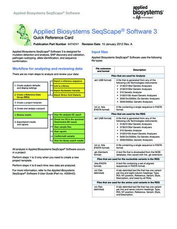
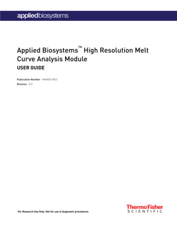
Performing a spatial calibration4. Click Start Calibration. The display updates as the run progresses.Note: If you engaged the optional QCCheck, and the average of any of theQC values exceeds the threshold, aSpatial QC Check error message isdisplayed. Click OK and re-run theSpatial Calibration.Evaluate thespatial calibrationprofileWhen the run is complete, evaluate the spatial calibration profile to ensure that yousee the following:1. One sharp peak for each capillary. Small shoulders may be acceptable.2. One marker ( ) at the apex of every peak. No off-apex markers.3. An even peak profile (all peaks about the same height).4. Spacing should be between 13 and 16.Note: If any peaks are lower than usual for the instrument or the heightsdrastically slope up or down, repeat the calibration with a fill. See the followingfigures for common acceptable Spatial Profiles.Figure 1 Acceptable spatial profiles (8-capillary: top, 24-capillary: bottom)5. If the results meet the criteria above, click Accept Results. If the results do notmeet the criteria listed above, click Reject Results, then refer to “Spatialcalibration troubleshooting” in the Applied Biosystems 3500/3500xL GeneticAnalyzer User Guide (Part no. 4401661) for troubleshooting information.Export or printspatial calibrationresults6To export spatial calibration results:Applied Biosystems 3500/3500xL Genetic Analyzer User Bulletin
1. Click Export Results.2. Enter an export file name.3. Select the export file type.4. Click Save.View or printspatial calibrationreportNote: Spatial and spectral calibration reports include the date on which a capillaryarray is installed for the first time on the instrument. Install Standard reports use themost recent install date if a capillary array was removed and re-installed on theinstrument.1. Click View Spatial Calibration Report.2. In the Report screen, click toolbar options to manipulate the report as needed.Place the mouse pointer over an item for a description of the item.3. To print the report, clickPrint.4. Close the report.IMPORTANT! After performing a calibration, you can save the calibration reportelectronically for record keeping. The software does not save historical calibration results.Only the most recent spatial calibration is maintained in the software. In the Printer dialogbox, select CutePDF Writer as the printer to print the report to a PDF file.For additional information on performing and evaluating a spatial calibration, referto the Applied Biosystems 3500/3500xL Genetic Analyzer User Guide (Part no. 4401661).Applied Biosystems 3500/3500xL Genetic Analyzer User Bulletin7
Performing a spectral calibrationPerforming a spectral calibrationA spectral calibration creates a matrix that corrects for the overlapping fluorescenceemission spectra of the dyes. Although each of these dyes emits its maximumfluorescence at a different wavelength, there is some overlap in the emission spectrabetween the dyes. The goal of multicomponent analysis is to effectively correct forspectral overlap and minimize the presence of artifacts, such as spectral pull-up, inthe data.A new spectral calibration is recommended when: The capillary array is changed or temporarily removed from the detectionblock.Note: Better dye separation is achieved when a new spectral calibration isperformed after removal or replacement of the capillary array and is thereforehighly recommended. The instrument is moved. The laser or CCD camera has been realigned/replaced by a service engineer. An increase in (pull-up and/or pull-down peaks) is observed. A new dye set is used on the instrument. The capillary array length or polymer type is changed. The detection cell door is opened (not required by the software, butrecommended).Prepare theinstrument1. If necessary, perform a spatial calibration as described in the previous section.2. In the Dashboard, check consumable status and ensure that: Consumables are not expired Adequate injections remain for consumables3. Ensure that the buffer levels are at the fill lines.4. Set the oven temperature to 60 C, then click Start Pre-heat.Note: Preheating for approximately 30 minutes helps mitigate subtle first-runmigration rate effects. The pre-heat function automatically turns off after 2hours.5. Check the pump assembly for bubbles and run the Remove Bubble wizard ifneeded.Prepare thestandardcalibration plate8For all chemicals, read the SDS, and follows the handling instructions. Wearappropriate protective eyewear, clothing, and gloves.Applied Biosystems 3500/3500xL Genetic Analyzer User Bulletin
1. Choose the appropriate Dye Set and Matrix Standards.For AmpFlSTR kits that use a.5-dye system, which includes thefollowing dyes: AmpFlSTR kit ExamplesAnd use.Matrix Standard Set DS-33(Dye Set G5)6FAM Identifiler Plus PCR Amplification Kit Identifiler PCR Amplification Kit Identifiler Direct PCR Amplification KitVIC NED PET LIZ NGM PCR Amplification Kit NGM SElect PCR Amplification Kit Yfiler PCR Amplification Kit SEfiler Plus PCR Amplification Kit Other five-dye AmpFlSTR kits4-dye system, which includes thefollowing dyes: Matrix Standard Set DS-32(Dye Set F)5FAM JOE NED ROX Profiler Plus PCR Amplification Kit COfiler PCR Amplification Kit Profiler Plus ID PCR Amplification Kit SGM Plus PCR Amplification Kit Other 4-dye AmpFlSTR kits2. Thaw and thoroughly vortex the Matrix Standard tube and spin the tube brieflyin a microcentrifuge.3. Prepare the Matrix Standard by combining the following in a labeled 1.5-mLcolorless microcentrifuge tube:ReagentMatrix Standard SetDS-33Matrix Standard SetDS-32(Dye Set G5)(Dye Set F)Matrix Standard (Part no. 4345833)3 µl4 µlHi-Di Formamide(Part no. 4311320)297 µl246 µlFinal Volume (1.5mL tube)300 µl250 µl4. Vortex thoroughly and spin the mixture briefly in a microcentrifuge.5. Heat the tube at 95 C for 5 minutes to denature the sample and immediatelyplace the tube on ice for 3 minutes.Note: In some instances, if the spectral calibration is of sub-optimal quality asdetermined by inspection of the calibration data or the presence of excess pullup in the test sample data, an improved spectral may be obtained byeliminating the chilling step after heating.6. Load 10 µL of the spectral calibration mixture into each well.Note: For a 96-well plate, use 10 µL of mixture per well. For a 384-well plate,use 5 µL of mixture per well. Add the mixture to wells A1-H1 on a 3500instrument or A1-H3 on a 3500xL instrument and load the plate assembly onthe instrument.Applied Biosystems 3500/3500xL Genetic Analyzer User Bulletin9
Performing a spectral calibrationIMPORTANT! You are not required to create a plate for the calibration. Thesoftware uses predetermined positions for the calibration.8-capillaryA1 through H196-well plate24-capillary96-well plateA1 through H1, A2 through H2, and A3through H37. Centrifuge the plate to ensure that the samples are at the bottom of the wells.IMPORTANT! If the reagents of any well contain bubbles or are not located atthe bottom of the well, briefly centrifuge the plate, remove the plate from thecentrifuge, and verify that each sample is positioned correctly in the bottom ofits well.Prepare the plateassembly1. Place the sample plate into the plate base.2. Align the holes in the septastrip with the wells of theplate, then firmly pressdownward onto the plate.IMPORTANT! Make sure touse the correct plate base forstandard plates versus 8-tubestrips and fast plates. Usingthe wrong plate base mayaffect performance.Plate retainerPlate withsepta stripPlate base3. Snap the plate retainer (cover)onto the plate, septa, and platebase.4. Verify that the holes of theplate retainer and the septa strip are aligned. If not aligned, re-assemble andthen assemble the plate assembly.IMPORTANT! The array tips will be damaged if the plate retainer and septastrip holes do not align correctly.Load the plate inthe instrument andinitiate thecalibrationIMPORTANT! Do not change electronic signature settings during a spectralcalibration.IMPORTANT! If you change polymer type, spectral calibrations for the originalpolymer type are not retained.The following are the basic steps to initiate the spectral calibration. Refer to theApplied Biosystems 3500/3500xL Genetic Analyzer User Guide (Part no. 4401661) formore information.10Applied Biosystems 3500/3500xL Genetic Analyzer User Bulletin
1. Place the plate in the autosampler with the labels facing outward and thenotched corner of the plate in the notched corner of the autosampler.2. Close the instrument door to re-initialize the instrument.3. Click Maintenance on the dashboard.4. Click on Spectral under Calibrate in the left navigation pane.5. Select the number of wells and plate position on the instrument.6. Select the chemistry standard and dye set.(Optional) Select Allow Borrowing to have a failed capillary use a neighboringcapillary’s spectral data. Refer to the Applied Biosystems 3500/3500xL GeneticAnalyzer User Guide (Part no. 4401661) for more information.5677. Click Start Run. The following occurs: The system sets up three injections. The Capillary Run Data display updates after each injection is complete. The status bar updates during Run 1.IMPORTANT! The status bar does not update during Run 2 or Run 3. Passing capillaries are shown in green and failing capillaries are shown inred. Borrowed capillaries are shown in yellow with an arrow indicating theadjacent capillary from which results were borrowed.Applied Biosystems 3500/3500xL Genetic Analyzer User Bulletin11
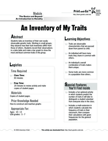
Performing a spectral calibration8. To display the result for each capillary (spectral data, Quality Value, andCondition Number) below the run results table, click a capillary in the table.Note: The ranges that the software uses to determine if a capillary passes or fails are:Dye SetQuality Value MinimumCondition Number MaximumAnyDye0.8 (default)20.0 (default)F0.958.5G50.9513.59. If the data for all capillaries meet the acceptance criteria, click the AcceptResults button.Note: If the data for all capillaries does not meet the acceptance criteria, click theReject Results button, repeat the analysis and begin the troubleshooting process. Formore information on troubleshooting spectral calibrations refer to the AppliedBiosystems 3500/3500xL Genetic Analyzer User Guide (Part no. 4401661).Evaluate thespectralcalibration dataThis section contains basic information regarding evaluation of the spectralcalibration data. For more information regarding evaluation of spectral calibrationdata, refer to the Applied Biosystems 3500/3500xL Genetic Analyzer User Guide (Part no.4401661).Excessive pull-up signal in the analyzed data is the most common manifestation of apoor quality spectral calibration. The following characteristics will assist the user indetermining if the spectral calibration may be suitable: Order of the peaks in the profile from left to right:F: Blue, green, yellow, redG5: Blue, green, yellow, red, orange No extraneous peaks in the raw data profile. No gross dips, overlaps or other irregular morphology. Spectral profile peaks are separate and distinct.12Applied Biosystems 3500/3500xL Genetic Analyzer User Bulletin
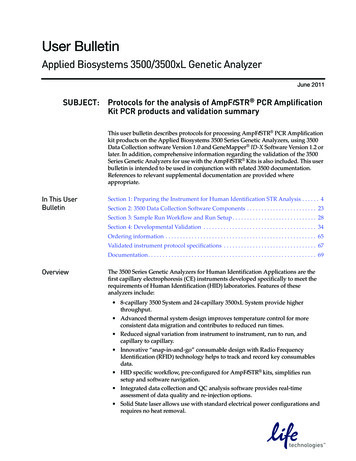
Ideally, spectral peak heights should be approximately similar to the peakheights typically analyzed by the laboratory.Figure 2 Order of the 4-dye (left) and 5-dye (right) spectral calibration peaksA spectral calibration automatically sets up three injections. The number ofinjections performed depends on the number of capillaries that pass or fail during aninjection and whether you select Allow Borrowing.When borrowing is disabled, all capillaries must meet passing criteria. Whenborrowing is enabled, all capillaries have to pass within the borrowing limits.For a successful calibration, there must be at least one passing attempt for eachcapillary within the three injection profile. A passing attempt is defined within theparameters set regarding borrowing and are described in the following section andin the Applied Biosystems 3500/3500xL Genetic Analyzer User Guide (Part no. 4401661).Spectral calibrations with borrowing disabledWhen borrowing is disabled, any failure in the quality value or condition numberwill prompt a reinjection of the matrix standards and new attempt at obtainingacceptable values. If, after all three injections, no runs are acceptable, the calibrationwill fail.Spectral calibrations with borrowing enabledWhen borrowing is enabled, the user can define the number of acceptable spectralfailures they will allow for a 3500xL (up to 3 maximum). For a 3500 series GeneticAnalyzer, only one failure is allowed.Any failure in the quality value or condition number will prompt a reinjection of thematrix standards and new attempt at obtaining acceptable values. If, after all threeinjections, no runs are acceptable, the calibration will fail.The results displayed when you click a borrowed capillary are the passing resultsborrowed from the adjacent capillary. To determine the reason that a capillary fails,view the spectral calibration report.Figure 3 Example of borrowing in a 3500 Series Genetic AnalyzerApplied Biosystems 3500/3500xL Genetic Analyzer User Bulletin13
Performing a spectral calibrationExport or printspectralcalibration resultsView and print a spectral calibration reportNote: Spatial and spectral calibration reports include the date on which a capillaryarray is installed for the first time on the instrument. Install Standard reports use themost recent install date if a capillary array was removed and re-installed on theinstrument.1. Click View Spectral Calibration Report.2. In the Report screen, click toolbar options to manipulate the report as needed.Place the mouse pointer over an item for a description of the item.3. To print the report, clickPrint.4. Close the report.IMPORTANT! Afterperforming acalibration, save the calibration report electronically for record keeping. Thesoftware does not save historical calibration results. Only the most recent spectralcalibration for each dye set is maintained in the software. To save the fileelectronically as a PDF, in the Printer dialog box, select CutePDF Writer as theprinter.Export spectral calibration resultsTo export spectral calibration results:1. Click Export Spectral Calibration Results.2. Specify an export file name and location.3. Click Save.14Applied Biosystems 3500/3500xL Genetic Analyzer User Bulletin
View the spectralcalibration historySelect History View, then select a dye set to view the associated calibration history.Performing a HID Install Standard performance checkThis section contains the basic information needed for performing the HID InstallStandard Performance Check. For more information on preparing the instrumentand running an instrument performance check, refer to the Applied Biosystems3500/3500xL Genetic Analyzer User Guide (Part no. 4401661).Note: While the Applied Biosystems 3500/3500xL Genetic Analyzer User Guide (Part no.4401661) recommends users perform the HID Install Standard Performance Checkmonthly, this is not a mandatory requirement for ongoing instrument operation inan HID laboratory. The HID Install Standard Performance Check is intended to beperformed at installation by a Life Technologies Field Service Engineer. Thisprocedure may be repeated by the Service Engineer during maintenance or servicevisits. It is not necessary to repeat this procedure after install and it is recommendedthat each HID laboratory determine the appropriate Quality Control measures toverify correct instrument operation. These measures may or may not includerepeated injections of allelic ladder to verify precision and correct genotypinginstead of performing the HID Install Standard Performance Check.Prepare thereagents1. Vortex the AmpFlSTR Identifiler , Identifiler Direct, or Identifiler Plusallelic ladder, GeneScan 600 LIZ Size Standard v2.0, and Hi-Di Formamide(if stored in aliquoted tubes) and spin each tube briefly in a microcentrifuge.2. Prepare performance-check chemistry by combining the following in a labeledcolorless 1.5-mL microcentrifuge tube:VolumeReagent35003500xLAllelic Ladder8 µL24 µLGeneScan 600 Liz Size Standard v2.04 µL12 µLHi-Di Formamide68 µL204 µLApplied Biosystems 3500/3500xL Genetic Analyzer User Bulletin15
Performing a HID Install Standard performance check3. Denature the sample at 95 C for 3 minutes, then store on ice until ready to use.4. Aliquot 10 µL of the mixture into each appropriate well of the plate as shownbelow.5. Load the standards in injection position 1 in the plate as shown:IMPORTANT! You do not create a plate for the performance check. Thesoftware uses predetermined positions for the performance check run. Youcannot specify standard location on the plate. If you do not place standards inthe positions indicated, the calibration will fail.8-capillaryA1 through H196-well plate24-capillary96-well plateA1 through H1, A2 through H2, and A3through H36. Briefly centrifuge the plate containing the standards.7. Verify that each sampleis positioned correctlyin the bottom of itswell.IMPORTANT! If thereagents of any wellcontain bubbles or arenot located at thebottom of the well,briefly centrifuge the plate, remove the plate from the centrifuge, and verifythat each sample is positioned correctly in the bottom of its well.Prepare the plateassembly1. Place the sample plate into the plate base.2. Align the holes in the septastrip with the wells of theplate, then firmly pressdownward onto the plate.IMPORTANT! Make sure touse the correct plate base forstandard plates versus 8-tubestrips and fast plates. Usingthe wrong plate base mayaffect performance.Plate retainerPlate withsepta stripPlate base3. Snap the plate retainer (cover)onto the plate, septa, and platebase.16Applied Biosystems 3500/3500xL Genetic Analyzer User Bulletin
4. Verify that the holes of the plate retainer and the septa strip are aligned. If notaligned, re-assemble and then assemble the plate assembly.IMPORTANT! The array tips will be damaged if the plate retainer and septastrip holes do not align correctly.Load the plate inthe instrument1. Place the plate in the autosampler with the labels facing you (or the instrumentdoor) and the notched corner of the plate in the notched corner of theautosampler.2. Close the instrument door to re-initialize the instrument.3. Access the HID Install Standard screen: SelectMaintenance, then select HID Install Standardin the navigation pane.4. Select the plate type and plate position in theinstrument.Note: You do not create a plate for theperformance check. The software usespredetermined positions for the run. Youcannot specify the standard locations on theplate.5. Click Start Run.Step4Step 5Applied Biosystems 3500/3500xL Genetic Analyzer User Bulletin17
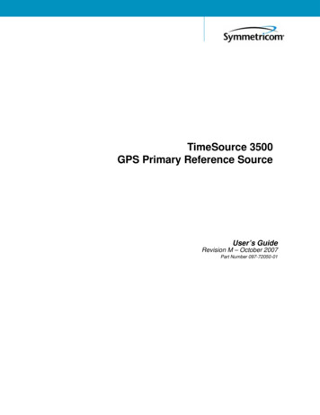
Performing a HID Install Standard performance checkWhat you seeduring a runThe system performs one run and indicates the number of observed allele and sizestandard peaks.The Capillary Run Data display updates after the run is complete. The number ofobserved size standard and allele peaks is shown. Results for each allele are shownat the bottom of the screen in the Run Information table.Note: The following example is for the HID install standard.Number of peaksper capillaryPlot and allelesize/heightinformation for theselected capillaryAllele results for allcapillariesHow the softwaredeterminespassing and failingcapillaries for thefragment/HIDperformance check18The software evaluates peaks in the data for each capillary. To be identified as apossible allele, peaks must be within the following ranges (nominal allele size, orreference bin size, is hard-coded): All markers except TH01: 0.7 bp of nominal size for the allele TH01: 0.5 bp of nominal size for the alleleFor all peaks that are within the nominal size range, the software calculates theAverage Peak Height and the Sizing Precision. Peaks that meet the followingthresholds pass.Applied Biosystems 3500/3500xL Genetic Analyzer User Bulletin
ResultAvg Peak HeightDescriptionThresholdAverage of peak heights for observed allele peaks of the includedcapillaries.Fragment: 175 RFUSizing PrecisionStandard deviation of the observed allele fragment sizes. 0.15 for expected allelesPass/FailAlleles with a sizing precision and average peak height that do not meet thresholds fail.HID: 400 RFUNote: Review the data for failed alleles as described below.ResultDescriptionFor information onlyNominal SizeExpected allele fragment peak size (bp).MeanAverage fragment size for the observed allele peaks.Peak Height % MinPercentage of observed allele peaks with a peak height above the minimum threshold.Sizing AccuracyDifference between the allele size and the mean allele size.Evaluatefragment/HIDinstall standarddata1. Examine the number of size standard and allele peaks found for each capillary.Note: The number of expected peaks shown below is for the HID installstandard.ExpectedObserved2. If the expected number of alleles and size standard peaks are found, clickAccept Results.If the expected number of alleles and size standard peaks are not found,troubleshoot as described below.Applied Biosystems 3500/3500xL Genetic Analyzer User Bulletin19
Performing a HID Install Standard performance checkTroubleshoot1. Click a capillary with fewerthan the expected number ofpeaks to display detailedinformation for each allele inthe table below the plot.2. Double-click the Sizecolumn to sort results andidentify the alleles that werenot found.A “0” Size value indicatesthat an all
Applied Biosystems 3500/3500xL Genetic Analyzer User Guide (Part no. 4401661) 3500 and 3500xL Genetic Analyzers Quick Reference Card (Part no. 4401662) GeneMapper ID-X Software Version 1.2 Quick Reference Card (Part no. 4426482) 3500 Data Collection v1.0 Software Release Notes (can be found on the 3500 Data Collection Software CD)