Transcription
VLT 3500 HVACContentsProduct Introduction1.1 Safety warnings . 21.2 Literature description . 31.3 Principle of the VLT 3500 HVAC . 4Section 1Section 2Mechanical and electrical installation2.1 Installation related product data . 52.2 Cabinet sizes of VLT 3500 HVAC . 82.3 Machanical installation . 102.4 Electrical installation . 132.5 CE-labelling . 172.6 EMC-correct installation . 192.7 Installation examples . 24Section 2Section 3Operation and programming3.1 Display and keypad . 333.2 Initialisation, return to factory setting . 383.3 Parameter overview . 393.4 Parameter group 0, operation and display . 403.5 Parameter group 1, Load and motor . 443.5.1 PID-controller . 473.6 Parameter group 2, references and limits . 513.7 Parameter group 3, start/stop functions . 563.8 Parameter group 4, inputs and outputs . 603.9 Parameter group 6, service and diagnostics . 71Section 3Section 4Diagnosis and service4.1 Status messages . 754.2 Warnings . 764.3 Alarm messages . 774.4 Fault messages . 784.5 Special conditions . 804.6 EMC test results . 824.7 Factory settings . 854.8 Customer parameter setting . 88Index . 89MG.35.B1.02 – VLT is a registered Danfoss trademark1Section 4Section 1
1.1 SafetyVLT 3500 HVAC Product IntroductionThe voltage of the frequency converteris dangerous whenever the equipmentis connected to mains. Incorrect installation of the motor or the frequency converter maycause damage to the equipment, serious personalinjury or death.Consequently, the instructions in this Design Guide,as well as national and local safety regulations, mustbe complied with.Touching the electrical parts may be fatal - even afterdisconnection from mains:Using VLT 3502-3562 HVAC: wait 4 minutesUsing VLT 3542-3562 (230 V) HVAC: wait 14 minutesUsing VLT 3575-3800 HVAC: wait 14 minutes Safety regulations1. The frequency converter must be disconnectedfrom mains if repair-work is to be carried out.2. The "Stop/Reset" key on the operating panel ofthe frequency converter does not disconnect theequipment from mains and is thus not to be usedas a safety switch.3. Correct protective grounding of the equipmentmust be established, the user must be protectedagainst supply voltage, and the motor must beprotected against overload in accordance withapplicable national and local regulations.4. Earth currents are higher than 3 mA. Warnings against unintended start1. The motor can be brought to a stop by means ofdigital commands, bus commands, references ora local stop, while the frequency converter isconnected to mains. If personal safety considerations make it necessary to ensure that nounintended start occurs, these stops are not sufficient.2. During programming of parameters, the motormay start. Consequently, the "Stop/Reset" stopkey must always be activated, following whichdata can be modified.3. A motor that has been stopped may start if faultsoccur in the electronics of the frequency converter,or if a temporary overload, a fault in the supplymains or a fault in the motor connection ceases.4. If the "Local/Hand" key is activated and the"Local" reference is modified, the motor can onlybe brought to a stop by means of the "Stop/Reset" key. For the North American marketCAUTION: It is the responsibility of the user or personinstalling the drive to provide proper grounding andbranch circuit protection for incoming power andmotor overload according to National Electrical Codes(NEC) and local codes.The Electronic Thermal Relay (ETR) in UL listed VLT sprovides class 20 motor overload protection in accordance with NEC in single motor applications, whenparameter 315 is set for "TRIP" and parameter 107 isset for rated motor (nameplate) current.Effective from software version 1.10.Warning:Touching the electrical parts may be fatal - even after theequipment has been disconnected from mains.Using VLT 3502-3562 HVAC: wait 4 minutesUsing VLT 3542-3562 (230 V) HVAC: wait 14 minutesUsing VLT 3575-3800 HVAC: wait 14 minutes2MG.35.B1.02 – VLT is a registered Danfoss trademark
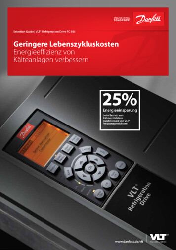
VLT 3500 HVACVLT 3502-3562 HVAC and VLT 3575-3800 HVACAppetizer AMB.35.DX.YYMB.35.EX.YYis for the user who has a greater need to utilize all thespecial functions offered by VLT 3500 HVAC. TheManual has largely the same contents as the DesignGuide. However, it is structured as a set of operatinginstructions for use when starting up, operating andinstalling a VLT 3500 HVAC frequency converter inmore complex systems.Design Guideis a tool to facilitate the sizing of systems in whichVLT 3500 HVAC frequency converters are ManualMG.10.AX.YYRFI - LCmoduleMI.65.FX.YYPROFIBUSData .CX.YYX Revision of editionYY Language versionMG.35.B1.02 – VLT is a registered Danfoss trademarkSection 4Appetizer BThe Manual:Section 3SalesleafletMB.35.CX.YYis an Installation Guide which helps the great majorityof users to get their VLT 3500 HVAC installed andstarted up very quickly.Section 2PromotionQuick Set-up:Section 1The manual progresses step-by-step through the different routines required wheninstalling and programming a VLT 3500 HVAC.The manual forms part of the literature concept supplied with VLT 3500 HVAC.When a VLT 3500 HVAC is supplied, it is accompanied by two documents: a QuickSet-up and a Manual.1.2 Literature description Introduction to the manual for VLT 3500 HVACThis manual is a tool for installation and programming the VLT 3500 HVAC frequencyconverters.HVAC stands for Heating Ventilation Air-Conditioning.This manual is valid for all VLT 3500 HVAC units with software version 3.0 and version3.11.The unit size and voltage is automatically identified when VLT 3500 HVAC is startedup.The following sizes of VLT 3500 HVAC are described in this manual:LCmoduleMI.65.FX.YY3
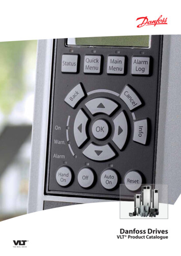
1.3 Principle of the VLT 3500 HVACVLT 3500 HVAC Principle of the VLT 3500 HVACA frequency converter rectifies AC voltage from themains supply into DC, and then modifies this into avariable AC voltage with variable amplitude andfrequency.1. Mains supply3 200 / 220 / 230 V A.C., 50 / 60 Hz3 380 / 400 / 415 V A.C., 50 / 60 Hz3 440 / 460 / 500 V A.C., 50 / 60 Hz.2. RectifierA three-phase rectifier bridge which rectifies ACinto DC.3. Intermediate circuitDirect current 2 x mains voltage [V].4. Intermediate circuit coilsEven out intermediate circuit voltage and reducemains supply interference from harmonic currents.5. Intermediate circuit capacitorEvens out the intermediate circuit voltage.6. InverterTransforms DC voltage into variable AC voltagewith variable frequency. Selection of options and accessoriesDanfoss offers a wide range of options and accessoriesfor the VLT 3500 HVAC. For additional information pleasecontact Danfoss.4The motor is thus supplied with variable voltage andfrequency, which enables infinitely variable speedregulation of three-phase, asynchronous standardmotors.7. Motor coilsAdvantages of motor coils: Long motor cables can be used. 100% protection against earthing andshort-circuiting. Unlimited number of switchings on thefrequency converter output.8. Motor voltageVariable AC current, 10-100% of the supplyvoltage.Variable frequency: 0.5-120 Hz.By regulating voltage and frequency (U/fcharacteristics) into a given ratio, the connected motor is enabled to supply the desired variable torque (VT) to the pump or fan.9. Control cardThis is where the computer is found that controlsthe inverter which generates the pulse pattern bywhich the DC voltage is transformed into variableAC voltage with variable frequency.NB!:In order to obtain satisfactory operation of thefrequency converter it is highly important to selectthe necessary options and accessories.MG.35.B1.02 – VLT is a registered Danfoss trademark
VLT 3500 HVAC2.1 Installation related product data Mechanical and electrical installation Installation related product data Mains supply 3 x 200/220/230 V or 3 x 220/230/240 VAccording to international VDE and UL/CSArequirementsVLT typeVLT3502 3504 3508 3511 3516 3522 3532 3542 3552 3562IVLT,N [A]IVLT, MAX (60 s) [A]Output (at 230 V)SVLT,N [kVA]Typical shaft outputPVLT,N [kW]Max. cable cross-section[mm2]Terminal torque[Nm]Max. motor cable length[m]Rated motor voltageUM,N [V]Rated motor frequencyfM,N [Hz]5.410.6 24.8 32.0 46.0 61.2 88.05.911.7 27.3 35.2 50.6 67.3 96.82.24.09.812.7 18.3 24.4 35.11.12.25.57.511.0 15.0 22.02.52.516.0 16.0 16.0 35.0 50.0300, with screened cables: 150 m fSW 4.5 30.0143.051.837.070.06154.0169.061.345.070.06Max. input currentIL,N [A]Max. cable cross-section[mm2]Terminal torque[Nm]Max. pre-fuses[A]Mains contactor4)[Danfoss type]5.42.516.0CI 6102.0120.031.1150.03CI 85128.0120.031.1150.03CI 85152.0120.031.1150.03CI 85[AC value]Supply voltage (VDE 0160)[V]Supply frequency[Hz]Power factor / cos. ϕ1Switching on inputtimes/min.Power loss atFrontmax. load.Heat sink[W]TotalAC-3 AC-3 AC-1 AC-13 x 200/220/230 10%50/600.9/1.0260130425580Ambient temperature-10 40, operation at full load 2)23)))29.616.050.0CI 1642.016.060.0CI 3256.835.080.0CI 3272.350.0125.01CI37AC-1 AC-1 AC-1 AC-1 AC-1 AC-1- 15%3 x 220/230/240 V 10%6519293575881350 9453944097128841106 1293Only semi-conductor fuses.In the range -10 to 0 C, the equipment can start and run; however, the display values andcertain operating characteristics will not fulfil the specifications.Bussmann rapid type JJS integrated.If mains contactors are used, the following Danfoss types are recommended:Max. ambient temperature 40 CSection 34)23.116.040.0CI 9Section 21[ C]10.62.525.0CI 12Section 1Output currentSection 4MG.35.B1.02 – VLT is a registered Danfoss trademark5
2.1 Installation related product dataVLT 3500 HVAC Mains supply 3 x 380/400/415 VAccording to international VDE and UL/CSArequirementsVLT typeVLT3502 3504 3505 3508 3511 3516 3522 3532 3542 3552 3562Output currentIVLT,N [A]IVLT, MAX (60 s) [A]Output (at 415 V)SVLT,N [kVA]Typical shaft outputPVLT,N [kW]Max. cable cross-section[mm2]Max. motor cable length[m]2.8 5.6 7.3 13.0 16.0 24.03.1 6.2 8.0 14.3 17.6 26.42.0 4.0 5.2 9.3 11.5 17.21.1 2.2 3.0 5.57.5 11.02.5 2.5 2.5 2.52.5 16.0300, with screened cables: 150 m 5)Rated motor voltageUM,N [V]Rated motor frequencyfM,N [Hz]Max. input currentIL,N [A]Max. cable cross-section[mm2]Max. pre-fuses[A][Danfoss type]Mains contactor4)[AC value]Supply voltage[V]Supply frequency[Hz]Power factor / cos. ϕ1Switching on inputtimes/min.380/400/41550/60/87/1002.8 5.6 7.3 13.0 17.0 22.02.5 2.5 2.5 2.52.5 16.0161616252550CI 6 CI 6 CI 9 CI 5 CI 6 CI 9AC-3 AC-3 AC-3 AC-3 AC-1 AC-13 x 380/400/415 10% (VDE 0160)50/60 Hz0.9/1.02Power loss at max. load60Ambient temperature[W][ C]13028030042536003625345)))57.535.080CI 32AC-166.5 80.035.0 50.0100 1) 125 1)CI 37 CI 45AC-1 AC-15808801390 1875 71602 x 12063684052652002 x 1206241.92672 x12031.1300CI 140AC-1293.33322 x 24042450-366.34052 x 1.71161531852261201202 x120 2 x12031.131.131.131.1150150250250CI 85CI 85CI 140 CI 140AC-1AC-1AC-1AC-13 x 380/400/415/440/460/500 10%50/600.9/1.01))41.516.063CI 32AC-13750Max. input current231.016.063CI 0.352.637.035.03650IVLT,N [A]IVLT,MAX (60 s) [A]Output (at 415 V)SVLT,N [kVA]Typical shaft outputPVLT,N [kW]Max. cable cross-section[mm2]Terminal torque[Nm]Max. motor cable length[m]Rated motor voltageUM,N [V]Rated motor frequencyfM,N [Hz]Power loss at max.load [W]Ambient 0-10 40 at full load )Output currentIL,N [A]IL,MAX (60 s) [A]Max. cable cross-section[mm2]Terminal troque[Nm]Pre-fuses 3)[A][Danfoss type]Mains contactor4)[AC value]Supply voltage (VDE 0160)[V]Supply frequency[Hz]Power factor / cos. ϕ1Switching on inputtimes/min.44.248.431.822.016.02VLT type 3575VLT610031.935.222.915.016.0Front 529713910Heat sink 107414471847[ C] –10 40 at full load 2)10912216Only semi-conductor fusesIn the range -10 to 0 C, the equipment can start and run; however, the display values andcertain operating characteristics will not fulfil the specifications.Bussmann rapid type JJS integrated.If mains contactors are used, the following Danfoss types are recommended:Max. ambient temperature 40 CVLT 3502-3505 fswitch 4,5 kHz; max. 40 m motor cable.MG.35.B1.02 – VLT is a registered Danfoss trademark
VLT 3500 HVACAccording to international VDE and UL/CSA VLT typerequirements3502 3504 3506 3508 3511 3516 3522 3532 3542 3552 3562IVLT,N [A]IVLT, Max (60 s) [A]Output (at 500 V)SVLT,N [kVA]Typical shaft outputPVLT,N [kW]Max. cable cross-section[mm2]Max. motor cable length[m]Rated motor voltageUM,N [V]Rated motor frequencyfM,N [Hz]2.64.88.212.6 14.4 21.8 27.92.95.39.013.9 15.9 24.0 30.72.34.17.110.9 12.4 18.9 24.21.12.24.05.57.5 11.0 15.02.52.52.52.52.5 16.0 16.0300, with screened cables: 150 m f SW 4.5 .050.0Max. input currentIL,N[A]Max. cable cross-section[mm2]Max. pre-fuses[A]Mains contactor4) [Danfoss type][AC value]Supply voltage[V]Supply frequency[Hz]Power factor / cos. ϕ1Switching on inputtimes/min.2.64.88.212.6 14.42.52.52.52.52.51616252525CI 6 CI 6 CI 9 CI 12 CI 15AC-3 AC-3 AC-3 AC-3 AC-33 x 440/460/500 10% (VDE 0160)50/600.9/1.0219.616.030CI 6AC-126.016.040CI 16AC-134.816.050CI 16AC-148.635.060CI 32AC-153.035.0100 1)CI 32AC-172.050.0125 1)CI 37AC-1Power loss at max. loadAmbient temperature60130160200–10 40 at full load 2)2813698801133 1440 1888VT [W][ C]393Section 1Output current2.1 Installation related product data Mains supply 3 x 440/460/500 VSection 2VLT type 23322622002 12063613973132502 1206Max. input currentIL,N [A]IL,MAX (60 s)[A]Max. cable cross-section[mm2]Terminal torque[Nm]Pre-fuses 3)[A]94.410612031.1150177.11982 12031.1250238.92642 12031.1300307.63322 24042450359.33972 24042500Mains contactor4)[Danfoss type][AC value]Supply voltage (VDE 0160)[V]Supply frequency[Hz]Power factor / cos. ϕ1Switching on inputtimes/min.CI 85CI 85CI 85CI 140 CI 140AC-1AC-1AC-1AC-1AC-13 380/400/415/440/460/500 10%50/600.9/1.01--Power loss atmax. load [W]Ambient temperature529713910107414471847-10 40 at full load 2)18123679220944851234))))FrontHeat sink[ C]123.413612031.1150155.31722 12031.12501091221615033051Section 4IVLT,N [A]IVLT,MAX (60 s)[A]Output (at 500 V)SVLT,N [kVA]Typical shaft outputPVLT,N [kW]Max. cable cross-section[mm2]Terminal torque[Nm]Max. motor cable length[m]Rated motor voltageUM,N [V]Rated motor frequencyfM,N [Hz]Section 3Output currentSemi-conductor fusesIn the range -10 to 0 C, the equipment can start and run; however, the display values andcertain operating characteristics will not fulfil the specifications.Bussmann rapid type JJS integrated.If mains contactors are used, the following Danfoss types are recommended:Max. ambient temperature 40 CMG.35.B1.02 – VLT is a registered Danfoss trademark7
2.2 Cabinet sizesVLT 3500 HVAC Cabinet sizes of VLT 3500 HV-AC VLT 3502-3532 200 - 230 3532ABCDabEnclosureIP 00IP 21IP 54IP 00IP 21IP 54IP 20IP 54IP 20IP 54IP 20IP 54IP 20IP 54IP 20IP 54mmmm 8178178178178178260280260280260280296280296280mm BAType A cabinet VLT 3502-3562 380 - 415/ 440 - 500 VVLTFrequencyconvertertypeAIP 00IP 00 w. RFI*3502IP 21IP 21 w. RFI*IP 54IP 00IP 00 w. RFI*3504IP 21IP 21 w. RFI*IP 54IP 00IP 00 w. RFI*3505*IP 21IP 21 w. RFI*IP 54IP 003506**IP 21IP 54IP 003508IP 21IP 54IP 003511*IP 21IP 543516IP 20IP 543522IP 20IP 543532IP 20IP 543542IP 20IP 543552IP 20IP 543562IP 20IP 54* Only for 380 - 415 V** Only for 440 - 500 80810950940950940950940mm 296280296280296280mm AAAAAAAAAAAAAAABABABABABABAType B cabinetMG.35.B1.02 – VLT is a registered Danfoss trademark
VLT 3500 HVAC2.2 Cabinet sizes VLT 3542 - 3562 230 V, 3575 - 3800 380 / 500 VFloorVLTFrequencyconvertertype3542-3562(230 V)3575-36003625-3700AEnclommsureIP 21IP 54IP 21IP 54IP 21IP 543750-3800954 1954 1954 1954 11569 11696 21569 11696 218771877WallFloorWallinstallationinstallation Cabineton baseleft/righttypeleft/right (mm)(mm)BmmCmmammbmmD installation installationmm on base above/belowmmmm506 3506 3506 3506 3513 525253123017017017017023013025 525 525 525 525 5CCCCC513 3513 3513 34175085311453 43231230260260230-13013013025 525 525 5CCC444Section 1IP 21444IP 541with ring bolts2with ring bolts and base3with hinges4to be placed on base5only limited by the hinges on the sides.Please note that the door opens to the left, while the option door opens to the right.Type C cabinetSection 2Section 3Section 4MG.35.B1.02 – VLT is a registered Danfoss trademark9
VLT 3500 HVAC2.3 Mechanical installation Mechanical installationWarningVLT 3500 HVAC must always beattached firmly to the wall or the floorbefore further installation work is carried out, so as toensure that no injury or damage occurs. This rulemust be complied with, especially with regard to thetypes of frequency converters that are top heavy. EMC-correct installationWith respect to mechanical installation, reference isalso made to chapter 2.6 on EMC-correct installation. General aspectsVLT 3500 HVAC is cooled by means of air circulation.Consequently, the air needs to be able to move freelyabove and below the frequency converter. VLT 3502-3562 HVACThis series must be installed on a plane surface toensure that the air flow is in contact with the heat sinkall the way from the bottom of the converter. VLT3500 HVAC has mounting holes in the side flanges.This means that two units can be installed flange toflange. Frequency converters without side flanges butwith mounting holes at top and bottom (IP 20) can beinstalled without any free space on the sides. VLT 3575-3700 and 3542-3562 HVACVLT 3575-3700, 380/500 V and VLT 3542-3562, 230 V,are supplied with a mounting bracket placed at the backof the converter. The mounting bracket also serves as anair duct for the heat sinks; the bracket must be mountedon the frequency converter before operation. Thebracket does not need to be removed for installationpurposes. However, it is possible to remove ittemporarily by loosening the coupling bolts from the inside of the converter.Remember to fasten the bracket again; otherwise therewill be a great risk of a trip because of overheating. The4 drip-shaped holes in the mounting bracket make itpossible to fasten the attachment bolts to the wall or inthe panel before hanging the unit.The attachment bolts are accessible through the top andbottom of the bracket, since a need to adjust tensionmay arise later on.VLT 3575-3600 HVAC, 380/500 V and VLT 3542-3562HVAC, 230V, are intended for wall installation only.VLT 3625-3700 HVAC is supplied for wall installation asstandard, but can be mounted on a base.VLT 3750-3800 is intended for floor installation only,which is why the base is supplied as part of the frequency converter.Drawing shows frequency converter seen from above.VLT 3500 HVAC can be installed with the flanges side byside. Base VLT 3625-3800 HVACAs an option to VLT 3625-3700 a base for floor installation can be supplied (ordering no.175L3047). VLT3750-3800 is intended for floor installation only, whichis why the base is supplied as part of the frequencyconverter. The base must be fastened to the floor bymeans of 4 bolts before installing the frequency converter. Unscrew the front plate of the base to fastenthe converter through the 4 top holes in the base.See also the section on cooling.The enclosure of the frequency converter ismade of steel. To avoid getting metal chipsin the electronics, the drilling of holes for cables isonly to be carried out after the unit has been installedin a vertical position.10MG.35.B1.02 – VLT is a registered Danfoss trademark
VLT 3500 HVAC Heat emission from VLT 3500 HVACThe table on page 5-7 show the power loss Pφ(W)from VLT 3500 HVAC. The maximum cooling airtemperature tIN, MAX is 40 at 100% load (of rated value). Ventilation of integrated VLT 3500 HVACThe quantity of air required for cooling frequencyconverters can be calculated as follows:3625-37001274953614 x 12.74453103750-38001274954954 x 12.7445445VLT type 3575* 3600 3625 3650 3700 3750 3800C [mm] 846 846 894 894 894 1008 1008R [mm] 505 505 513 513 513 513 513Dimensions for VLT 3575 also apply to VLT 35423562, 230 volts.m3/hInsert t in KelvinThe outlet from the ventilation must be placedabove the highest-mounted frequency converter.Allowance must be made for the pressure lossacross the filters and for the fact that the pressureis going to drop as the filters are choked. ExampleTotal power loss and total quantity of air required at100% load for eight VLT 3508 HVAC (380 volts)integrated in the same panel. The cooling air temperature (tIN) 40 C and themax. cooling air outlet temperature (tOUT, MAX) 45 C.PΦ 280 W and tIN, MAX 40 C.1. ΣPΦ 8xPΦ(W) tIN, MAX 2240 W.Section 4*ΣPϕ x 3.1 t2. t 45 C-tIN 45 C-40 C 5 K.3. Quantity of air (at 40 C) 2240 x 3.1 1388 m3/h5MG.35.B1.02 – VLT is a registered Danfoss trademarkSection 3 Front door VLT 3542-3562 (230V), 3575-3800HVACThe front door for VLT 3542-3562 (230V) and 35753800 HVAC is hinged on the left-hand side.The table below gives the door radius and the necessary distance from the mounting surface for the doorto be able to open freely:quantity of air Section 2The bases for VLT 3500 HVAC and options have beenupdated to fit VLT 3625-3800 with its detachablebottom plate. Please note that the ventilation slitshave been replaced by two apertures in the sides. If abase for the mounting cabinet and RFI in IP 54 enclosure are also used, make sure that the ventilationapertures match.A base of the new design can be used with previousversions of VLT 3625-3800 HVAC; however, a basewith the previous design must never be used forfrequency converters with a detachable bottom plate.Section 1VLT typeA [mm]B [mm]C [mm]D [mm]b [mm]c [mm]1. Add up the values of PΦ for all the frequencyconverters to be integrated in the same panel.The highest cooling air temperature (tIN) presentmust be lower than tIN, MAX (40 C).The day/night average must be 5 C lower(VDE 160).The outlet temperature of the cooling air must notexceed: tOUT, MAX (45 C).2. Calculate the permissible difference between thetemperature of the cooling air (tIN) and its outlettemperature (tOUT): t 45 C-tIN.3. Calculate the required2.3 Mechanical installationThe drawing shows the base and its dimensions.11
2.3 Mechanical installationVLT 3500 HVAC CoolingTo enable the frequency converter to get rid of thecooling air, there must be a free air space above andbelow the unit.The minimum distance of this air space depends onthe frequency converter model and the enclosure.For VLT type 3502-3562 HVAC the following applies:EnclosureIP 00IP 21IP 20IP 54For VLT type 3575-3700 HVAC, 380/500 V and VLTtype 3542-3562, 230 V, which are wall-mounted, thefollowing applies:Please note that the frequency convertercan be installed without any free space tothe sides; however, the hinges must beable to move freely;(Distance B).Model3542-35623575-36003625-3700For VLT type 3625-3800 HVAC installed on the floorthe following applies:A150 mm150 mm200 mm150 mmModel3625-37003750-3800A230260B252525(A) Top A (Bottom)170170170170230230B130130The sidewards distance to the next VLT 3500 HVACmust be 130 mm to allow the base to take in air atthe side. VLT type 3575-3800 HVAC has a fan in thefront door which cools down the internal components.A distance which allows free opening of the door issufficient in front of the frequency converter.See the section: Door radius VLT 3575-3800 HVAC.12MG.35.B1.02 – VLT is a registered Danfoss trademark
VLT 3500 HVACElectrical installationWarning:The frequency converter voltage isdangerous when connected to mainsand up to 14 minutes after the unit hasbeen disconnected. Electrical installation is therefore only to be carried out by a qualifiedelectrician.Incorrect mounting of the motor or the frequency converter may result in damge to the equipment, seriouspersonal injury or death. Consequently, the instructions of this Design Guide must be complied with,together with national and local safety regulations.Correct size and dimensioning can be seen from thesection on technical data, pages 5-7.For VLT type 3575-3800 HVAC, 380/500 V and VLT3542-3562 HVAC, 230V, the pre-fuses are included inthe mains connection of the frequency converter.MainsMotorSection 4MG.35.B1.02 – VLT is a registered Danfoss trademark Mains and motor connection for VLT 3502-3562HVAC, 200/380/500 V (not 3542-3562, 230 V)The max. cable cross-section and the correspondingmax. length and terminal size can be seen from thesection on technical data, pages 5-7.The mains supply and the motor are connected inaccordance with the drawing below.Section 3 Extra protectionEarth fault voltage relays, protective multiple earthingor protective grounding can be used as extra protection.However, such an installation must comply with localhealth and safety standards.An earth fault can introduce a DC current in the discharge current.If FI relays are used, local regulations must becomplied with.The relays must be suitable for protecting 3-phaseequipment with bridge rectifier and a short dischargeon power-up.The electronic thermo relay (ETR) cannot be used ifthe motors operate in parallel. ETR has been ULapproved for operating individual motors - when parameter 315 has been set to trip, parameter 311 hasbeen set to 0 sec., and parameter 107 has beenprogrammed to match the rated motor (nameplate)current.Section 2 Pre-fusesFor VLT type 3502-3562 external pre-fuses must beinstalled in the power supply for the frequency converter.The motor cable screen is connected to both thefrequency converter and the motor. The frequencyconverter has been tested using a given length ofscreened cable and a specific cross-section. If thecross-section is increased, the discharge capacity ofthe cable goes up and so does the discharge current.This means that the cable must be shortened correspondingly.Section 1NB!:It is the responsibility of the user or the electrician to ensure that protection against earthingis established in accordance with applicable national and local standards. GeneralThe terminals for both the 3-phase mains supply andthe motor are placed in the lower half of the enclosureof the frequency converter.2.4 Electrical installation 13
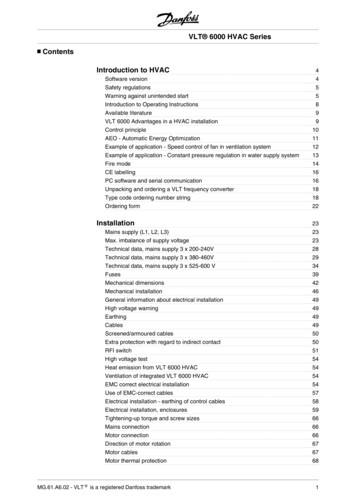
2.4 Electrical installationVLT 3500 HVAC Mains and motor connection of VLT 3575-3600HVAC and VLT 3542-3562 (230 V) HVACVLT 3575-3600,VLT 3625-3700VLT 3542-3562 (230)VLT 3750-3800 Motor connectionAll types of three-phase asynchronous standard motors can be used together with VLT 3500 HVAC.In general, smaller motors (220/380 V, / Y) are starconnected. Larger motors (380/660 V, / Y) are deltaconnected.The correct connection mode and voltage can beseen from the nameplate on the motor. Direction of rotationThe factory setting gives clockwise rotation when theoutput on the VLT 3500 HVAC has been connectedas follows:Terminal 96: connected to UTerminal 97: connected to VTerminal 98: connected to WThe direction of rotation can be changed by swappingtwo phases of the motor cable.14MG.35.B1.02 – VLT is a registered Danfoss trademark
VLT 3500 HVAC2.4 Electrical installationSection 1Section 2VLT type3502 - 3511 HVAC, 380 V3502 - 3504 HVAC, 200 V3502 - 3511 HVAC, 380/500 VVLT type3516 - 3562 HVAC, 380/500 V3508 - 3532 HVAC, 200 VVLT type3575 - 3800 HVAC, 380/500 V3542 - 3562 HVAC, 230 VSection 3 Parallel connection of motorsVLT 3500 HVAC can control several motors connected in parallel. If the motor speeds are to be different,motors of different rated speeds must be used. Thespeed of the motors changes simultaneously, whichm
This manual is a tool for installation and programming the VLT 3500 HVAC frequency converters. HVAC stands for Heating Ventilation Air-Conditioning. This manual is valid for all VLT 3500 HVAC units with software version 3.0 and version 3.11. The unit size and voltage is automatically identified when VLT 3500 HVAC is started up.