Transcription
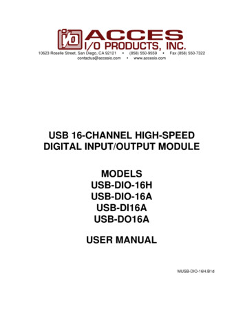
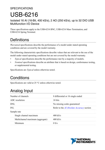
USB Digital I/OUSB-DIO24, -1024, and -DIO96H SeriesFeatures 24 digital I/O (USB-DIO24Series and USB-1024 Series) or96 digital I/O(USB-DIO96H Series) High current output available Event counter availableUSB-DIO24 Series boards (left) provide 24 DIO. The USB-1024 Series (middle) provide thesame functionality as the USB-DIO24 Series and are shipped in a case. USB-DIO96H Series(right) provide 96 DIO, high-drive current output and are shipped in a metal enclosure.OverviewSupported Operating SystemsThe USB-DIO24, -1024, and -DIO96H Series are digital I/O data acquisition devices. Windows 10/8/7/Vista /XP32/64-bitThe USB-1024 Series adds 24 lines of logic-level digital I/O to any USB port. TheUSB-1024HLS high output current can drive many logic level devices directly,eliminating the need for costly buffer circuitry.The USB-DIO24 Series has all the functionality of the USB-1024 Series, but isenclosed in a case and designed with a D connector that matches the PCI-DIO24,making it easy to replace PCI boards in your applications.USB-DIO96H SeriesThe USB-DIO96H Series provides 96 lines of high-current, logic-level, bidirectionaldigital I/O. The units offer 4 independent 24-bit DIO groups, each divided intotwo 8-bit ports and two 4-bit ports. The outputs can drive a wide assortment ofexternal devices directly, without additional buffering. USB-DIO96H Series arehoused in a heavy-duty chassis with integrated mounting slots.Digital I/OUSB-DIO24 Series and USB-1024 SeriesUSB-DIO24 and USB-1024 Series provide24 DIO channels configured as either twobanks of eight ports and two banks offour ports, or three banks of eight ports.Each port is independently configurablefor input or output.The USB-DIO24/37 and USB-1024LS aredesigned with an 82C55 interface chip. Available as board-only(USB-DIO24 Series), enclosed ina housing (USB-DIO96H Series),or cased (USB-1024 Series)The USB-DIO24H/37 and USB-1024HLSare designed to emulate 82C55 mode 0.Outputs arehigh-drive TTL that can source15 mA and sink 64 mA.Digital I/O lines are accessed througha 37-pin D-type connector on theUSB-DIO24 Series, and through screwterminals on the USB-1024 Series. USBDIO24 Series are board-only, while theUSB-1024 Series are shipped in a case.The USB-DIO96H Series provides 96 DIOchannels that are configured as eightbanks of eight ports and eight banks offour ports. Each port is independentlyconfigurable for input or output. USBDIO96H Series devices are designed toemulate 82C55 mode 0. Digital outputsare high-drive TTL that can source 24mA/sink 64 mA.Digital I/O lines are accessed through thescrew terminals on the USB-DIO96H, andthrough the header connectors on theUSB-DIO96H/50. USB-DIO96H Seriesboards are shipped in a rugged metalenclosure that you can mount on a DINrail or bench.USB-DIO24 Series, USB-1024 Series, and USB-DIO96H Series Selection ChartMax Input VoltageSignal I/O2.5 mA5.5 V37-pin D-type64 mA15 mA5.5 V37-pin D-typeModelDigital TypeUSB-DIO24/3782C552.5 mAUSB-DIO24H/37Output: 74FCT244Input: 74ACT373Source(per output)Sink(per output)USB-1024LS82C552.5 mA2.5 mA5.5 V40-pin screw terminalsUSB-1024HLSOutput: 74FCT244Input: 74ACT37364 mA15 mA5.5 V40-pin screw terminalsUSB-DIO96HOutput: 74ABT244AInput: 74ACT37364 mA24 mA5.5 V96-pin screw terminalsFour 50-pin IDC-type headersUSB-DIO96H/50Output: 74ABT244AInput: 74ACT37364 mA24 mA5.5 VTwo 50-pin IDC-type headers1
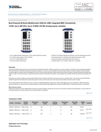
USB Digital I/OGeneral InformationUSB-DIO24 Series and USB-1024 Series Block Diagram82C55 (USB-DIO24/37)PORT A (7:0)PORT APORT B (7:0)PORT CH (3:0)PORT CL (3:0)PORT BPORT CHControlScrew terminal I/O ConnectorHigh-drive 82C55 Emulation (USB-DIO24H/37)8USBMicrocontroller132-bitEvent Counter500 mAUSB 2.0PORT CLUSB-DIO96H Series Block DiagramHIGH DRIVEFOURTHPORT88445V PORTCHFOURTHPORTCLPowerMonitorHIGH DRIVETHIRDPORT884Signal DPORTCL24HIGH DRIVESECONDPORT884496LogicController(CPLD)844500 mAUSB DPORTCHSECONDPORTCL32-bitevent counter1 channelHIGH ORTB124FIRSTPORTCHFIRSTPORTCLCounter InputPowerThe USB-DIO24 Series, USB-1024 Series, and USB-DIO96H provide a 32-bit event counter to count TTL pulses. The counteraccepts inputs up to 1 MHz.Power to the USB-DIO24 Series and USB-1024 Series is suppliedby the 5 volt USB supply from your computer. No externalpower is required.Power to the USB-DIO96H Series is provided by an external 5 volt regulated power supply. An onboard Molex connectoris available to connect an alternate user-supplied power supply.2
USB Digital I/OSoftwareUSB-DIO24, -1024, and -DIO96H Series devices are supported by the software in the table below.Ready-to-Run ApplicationsDAQami InstaCalTracerDAQ andTracerDAQ ProData acquisition companion software with drag-and-drop interface that is used to acquire,view, and log data, and generate signals. DAQami can be configured to log analog, digital, andcounter channels, and to view that data in real-time or post-acquisition on user-configurabledisplays. Logged data can be exported for use in Excel or MATLAB . Windows OSDAQami is included with the free MCC DAQ Software bundle (CD/download). Install DAQamiand try the fully-functional software for 30 days. After 30 days, all features except for data logging and data export will continue to be available – data logging and data export features canbe unlocked by purchasing the software.An interactive installation, configuration, and test utility for MCC hardware. Windows OSInstaCal is included with the free MCC DAQ Software bundle (CD/download).Virtual strip chart, oscilloscope, function generator, and rate generator applications used togenerate, acquire, analyze, display, and export data. Supported features may vary by hardware.The Pro version provides enhanced features. Windows OSTracerDAQ is included with the free MCC DAQ Software bundle (CD/download).TracerDAQ Pro is available as a purchased software download.General-Purpose Programming SupportUniversal Library(UL)Linux DriverLibrary for developing applications in C, C , VB, C# .Net, VB .Net, and Python.Windows OSThe UL is included with the free MCC DAQ Software bundle (CD/download).Open-source Linux drivers are available for most MCC devices. Example programs are alsoprovided.Application-Specific Programming SupportULx forNI LabVIEW DASYLab A comprehensive library of VIs and example programs for NI LabVIEW that is used to developcustom applications that interact with most MCC devices. Windows OSULx for NI LabVIEW is included with the free MCC DAQ Software bundle (CD/download).Icon-based data acquisition, graphics, control, and analysis software that allows users to createcomplex applications in minimal time without text-based programming. Windows OSDASYLab is available as a purchased software download.MATLAB DriverHigh-level language and interactive environment for numerical computation,visualization, and programming. The Mathworks Data Acquisition Toolbox allows users toacquire data from most MCC PCI and USB devices.Visit www.MathWorks.com for more information on the Data Acquisition Toolbox.3
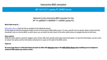
USB Digital I/OSpecificationsSignal Conditioning AccessoriesSpecifications: USB-DIO24/37 andUSB-DIO24H/37For digital signal conditioning, connect to Measurement Computing relay mounting and interface boards:Digital Input/OutputCIO-ERB08 and CIO-SERB08The CIO-ERB48 is a relay accessory board that includes 48 FormC relays. The CIO-SERB48 provides similar functionality withsocketed relays Both accessory boards have a 50-pin headerconnector for interfacing with the USB-DIO96H/50.Digital typeUSB-DIO24: 82C55USB-DIO24H/37Input: 74ACT373Output: 74FCT244Number of I/O: 24 (Port A Bit 0 through Port C Bit7)Configuration: 2 banks of 8 and 2 banks of 4, or 3 banks of 8Pull-up/down configuration: all pins pulled up to 5V via 47 kΩ resistors (default).Selection available for pull down to ground. Hardware selectable via 0 Ω resistor.Input high voltage: 2.0 V min, 5.5 V absolute maxInput low voltage: 0.8 V max, –0.5 V absolute minOutput high voltageUSB-DIO24/37 (IOH –2.5 mA): 3.0 V minUSB-DIO24H/37 (IOH –15 mA): 2.4 V minOutput low voltageUSB-DIO24/37 (IOH –2.5 mA): 0.4 V maxUSB-DIO24H/37 (IOH 64 mA): 0.55 V maxSource current (USB-DIO24H/37)Self-powered hub or externally powered root port hub: 15 mA per output,max. Bus-powered or battery-powered root port hubs are not supported.Sink current (USB-DIO24H/37):365 mA/(number of outputs), max. 64 mA max sink current for any singleoutput. A low-side resettable fuse protects the USB-DIO24H/37. This is designedto protect the host PC or hub from an over current condition. Assuming allreturn currents in sinking applications return via the USB cable ground signal,the maximum allowable return current is 500 mA. Include the USB-DIO24H/37unloaded operating current (135 mA) in your power budget.Power up / reset state: Input mode CounterThe CIO-ERB08 is a relay accessory board that includes 8 FormC relays. The CIO-SERB08 provides similar functionality withsocketed relays. Both accessory boards have two 37-pin connectors for interfacing with USB-DIO24 Series hardware. Connect to the USB-DIO24 Series with a C37FF-x cable.CIO-ERB24 and CIO-SERB24/FDThe CIO-ERB24 is a relay accessory board that includes 24 FormC relays. The CIO-SERB24/FD provides similar functionality withsocketed relays and fault detection. Both accessory boards havea 37-pin D-type connector and a 50-pin header connector forinterfacing with USB-DIO24 Series and USB-DIO96H/50 devices. Connect to the USB-DIO24 Series with a C37FF-x cable. Connect to the USB-DIO96H/50 with C50FF-x cables.CIO-ERB48 and CIO-SERB48Connect to the USB-DIO96H/50 with C50FF-x cables.Pin name: CTR; Schmitt trigger input.Counter type: Event counterNumber of channels: 1Input type: TTL, rising edge triggeredInput source: CTR screw terminalResolution: 32 bitsSchmidt trigger hysteresis: 20 mV to 100 mVInput leakage current: 1 µAMaximum input frequency: 1 MHzHigh pulse width: 500 ns minLow pulse width: 500 ns minInput low voltage: 0 V min, 1.0 V maxInput high voltage: 4.0 V min, 15.0 V maxSSR-RACK08The SSR-RACK08 is a relay accessory board that provides mounting locations for eight Gordos or Opto 22 type solid-state I/Omodules. The board has two 37-pin D connectors for interfacingwith USB-DIO24 Series hardware. Connect to the USB-DIO24 Series with a C37FF-x cable.SSR-RACK24The SSR-RACK24 is a relay accessory board that providesmounting locations for 24 Gordos or Opto 22 type solid-stateI/O modules. The board has one 37-pin D connector and two50-pin header connectors for interfacing with USB-DIO24 Seriesand USB-DIO96H/50 hardware. Connect to the USB-DIO24 Series with a C37FF-x cable. Connect to the USB-DIO96H/50 with C50FF-x cables.Data Transfer RatesDigital I/O transfer rates (software paced)Digital input: 62 port reads or single bit reads per second (typ)Digital output: 125 port writes or single bit writes per second (typ)Counter/timer read/write rates (software paced)Counter read: 62 port reads per second (typ)Counter clear: 125 port writes per second (typ)PowerSSR-RACK48Supply current:USB-DIO24/37: 20 mA typ, 40 mA max. (Total current requirement; includesup to 5 mA for the status LED.)USB-DIO24H/37: 100 mA typ, 135 mA max. (Total current; no load)USB 5V power availableConnected to self-powered hubUSB-DIO24/37: 4.5 V min, 5.25 V maxUSB-DIO24H/37: (350 mA) – (total output source current)Connected to bus-powered hubUSB-DIO24/37: 4.1 V min, 5.25 V maxUSB-DIO24H/37: 4.75 V min, 5.25 V maxSelf-powered refers to USB hubs/hosts with a power supply. Bus-powered refers toUSB hubs/hosts without a power supply. Bus-powered hubs provide downstreamUSB power as low as 4.4 V. Guaranteed performance requires a minimum supplyvoltage of 4.75 V. Self-powered and root port hubs meet this minimum.The SSR-RACK48 is a high-density relay accessory board thatprovides mounting locations for 12 quad relays. The boardhas one 50-pin header connector for interfacing with the USBDIO96H/50. Connect to the USB-DIO96H/50 with C50FF-x cables.4
USB Digital I/OSpecificationsOutput current (USB-DIO24/37)Connected to self-powered hub: 460 mA maxConnected to bus-powered hub: 60 mA max. This is the total amount of currentthat can be sourced from the USB 5V and digital outputs.Over-current protection (USB-DIO24H/37); resettable fuseHold current: 350 mA, typTrip current: 700 mA typTrip/recovery time: 100 ms, maxOn resistance: 1.3 maxHigh pulse width: 500 ns minLow pulse width: 500 ns minInput low voltage: 0 V min, 1.0 V maxInput high voltage: 4.0 V min, 15.0 V maxPowerSupply currentUSB-1024LS: 20 mA typ, 40 mA max. (Total current requirement; includes upto 5 mA for the status LED.)USB-1024HLS: 80 mA typ, 135 mA max. (Total current requirement; no load)Input power requirementsUSB-1024HLS: 4.75 V min, 5.25 V max.Bus-powered hubs provide downstream USB power as low as 4.4 V. Guaranteedperformance requires a minimum supply voltage of 4.75 V. Self-powered androot port hubs meet this minimum.USB 5V power availableConnected to self-powered hubUSB-1024LS: 4.5 V min, 5.25 V maxUSB-1024HLS: 4.4 V min, 5.25 V maxSelf-powered refers to USB hubs and hosts with a power supply.Connected to bus-powered hubUSB-1024LS: 4.1 V min, 5.25 V maxBus-powered refers to USB hubs and hosts without their own power supply.Output currentConnected to self-powered hubUSB-1024LS: 460 mA maxUSB-1024HLS: (350 mA) – (total output source current)Connected to bus-powered hubUSB-1024LS: 60 mA max. This is the total amount of current that can besourced from the USB 5V and digital outputs.Over-current protection (USB-1024HLS); resettable fuseHold current: 350 mA, typTrip current: 700 mA typTrip/recovery time: 100 ms, maxOn resistance: 1.3 maxGeneralUSB controller clock error:25 C: 30 ppm max0 C to 70 C: 50 ppm maxDevice type: USB 1.1 low-speedDevice compatibility: USB 1.1, USB 2.0EnvironmentalOperating temperature range: 0 C to 70 CStorage temperature range: –40 C to 85 CHumidity: 0% to 90% non-condensingMechanicalDimensions (L W H): 119 84 14 mm (4.68 3.31 0.55 in.)USB cable length: 3 m (9.8 ft)USB cable type: A-B cable, UL type AWM 2725 or equivalent.Min 24 AWG VBUS/GND, min 28 AWG D /D–Specifications: USB-1024LS andUSB-1024HLSDigital Input/OutputDigital typeUSB-1024LS: 82C55USB-1024HLSInput: 74ACT373Output: 74FCT244Number of I/O: 24 (Port A Bit 0 through Port C Bit7)Configuration: 2 banks of 8 and 2 banks of 4, or 3 banks of 8Pull up/pull-down configuration:All pins pulled up to 5V via 47 kΩ resistors (default). Selection available for pulldown to ground. Hardware selectable via zero Ω resistor.Input high voltage: 2.0 V min, 5.5 V absolute maxInput low voltage: 0.8 V max, –0.5 V absolute minOutput high voltageUSB-1024LS (IOH –2.5 mA): 3.0 V minUSB-1024HLS (IOH –15 mA): 2.4 V minOutput low voltageUSB-1024LS (IOH –2.5 mA): 0.4 V maxUSB-1024HLS (IOH 64 mA): 0.55 V maxSource current (USB-1024HLS)Self-powered hub or externally powered root port hub: 15 mA per output,max. Bus-powered or battery-powered root port hubs are not supported.Sink current (USB-1024HLS):365 mA/(number of outputs), max. 64 mA max sink current for any singleoutput. A low-side resettable fuse protects the USB-1024HLS. This is designedto protect the host PC or hub from an over current condition. Assuming allreturn currents in sinking applications return via the USB cable ground signal,the maximum allowable return current is 500 mA. Include the USB-1024HLSunloaded operating current (135 mA) in your power budget.Power up / reset state: Input mode (high impedance)GeneralUSB controller clock error:25 C: 30 ppm max0 C to 70 C: 50 ppm maxDevice type: USB 1.1 low-speedDevice compatibility: USB 1.1, USB 2.0EnvironmentalOperating temperature range: 0 C to 70 CStorage temperature range: –40 C to 70 CHumidity: 0% to 90% non-condensingMechanicalDimensions (L W H): 79 82 25 mm (3.11 3.23 0.98 in.)USB cable length: 3 m (9.8 ft)USB cable type: A-B cable, UL type AWM 2725 or equivalent.Min 24 AWG VBUS/GND, min 28 AWG D /D–Specifications: USB-DIO96H andUSB-DIO96H/50Digital Input/OutputOutput: 74ABT244AInput: 74ACT373;USB-DIO96H hardware revision G and later: 74LCX24Configuration: Eight banks of 8, eight banks of 4, programmable by bank asinput or outputPull-up/down: High impedance pull-up/down selectable with DIP switch foreach digital input port.Number of I/O: 96Output high: 2.0 V min @ –24 mAOutput low: 0.5 V max @ 64 mAInput high: 2.0 V min, 5.5 V maxInput low: 0.8 V max, –0.5 V absolute minInput impedance: 47 k (series resistance)Source current: 24 mA per output maxCounterPin name: CTR; Schmitt trigger input.Counter type: Event counterNumber of channels: 1Input type: TTL, rising edge triggeredInput source: CTR screw terminalResolution: 32 bitsSchmidt trigger hysteresis: 20 mV to 100 mVInput leakage current: 1 µAMaximum input frequency: 1 MHz5
USB Digital I/OOrdering InformationSink current: 64 mA per output maxPower-up state: Input modeDebounce mode (available through firmware): samples all inputs eight timesover a specified interval, and latches out the input state when eight consecutive samples are identical (all 0 or all 1). Debouncing intervals: 1 ms, 2 ms,5 ms, 10 ms, 20 ms, 50 ms, 100 ms, 200 ms, and 400 ms.Debounce interval accuracy: 0% / –12.5%Note: The board revision may be determined from the part number label on thehousing that states “193770X-01L”, where X is the board revision.Data Transfer RatesCounter (USB-DIO96H only)Operating temperature range: 0 C to 60 CStorage temperature range: –40 C to 85 CHumidity: 0% to 90% non-condensingDigital I/O transfer rates (software paced):System dependent, 33 to 250 port reads/writes or single bit reads/writes persecond typCounter/timer read/write rates (software paced); USB-DIO96H only:Counter read: system dependent, 33 to 250 reads per secondCounter clear: system-dependent, 33 to 250 writes per secondEnvironmentalPin name: CTR; Schmitt trigger input protected with a 1.5 k series resistor.Counter type: Event counterNumber of channels: 1Input source: CTR screw terminalInput type: TTL, rising edge triggeredResolution: 32 bitsInput high voltage limit: 5.0 V recommended max, 5.5 V absolute maxInput low voltage limit: 0 V recommended min, –0.5 V absolute minMaximum input frequency: 1 MHzHigh pulse width: 500 ns minLow pulse width: 500 ns minMechanicalBoard dimensions (L W H): 304.8 121.9 20.0 mm (12.0 4.8 0.8 in.)Enclosure dimensions (L W H):342.9 125.7 58.9 mm (13.50 4.95 2.32 in.)PowerUSB 5 V input voltage range: 4.75 V min to 5.25 V maxUSB 5 V supply current (all modes of operation): 100 mAExternal power input: 5 VDC 5% (5 VDC power supply provided). Voltagespecification applies at barrel plug power input. If a different power supply isused, small line resistances could cause significant voltage drop between thepower supply and the barrel plug input.External power supply (MCC p/n PS-5V3AEPS included):5 VDC, 15 W, 5% regulationAlternate external power supply (from PC aux power; cable not included):Jumper selectable Molex connector internal to caseVoltage supervisor limits:4.13 V Vext or Vext 5.59 V: PWR LED Off; (power fault)4.13 V Vext 5.59 V: PWR LED OnPower supply current: 2.7 A maxUser 5 V output voltage range (available at 5 V screw terminals):4.0 V min, 5.25 V maxUser 5 V output current available (total from all 5 V screw terminals):50 mA maxHardware revision F and earlier:Input type: Schmitt trigger, rising edge triggered, 1.5 k input series resistorSchmitt trigger hysteresis: 20 mV min, 100 mV maxInput high voltage threshold: 4.0 V maxInput low voltage threshold: 1.0 V minHardware revisions G and later:Input type: Schmitt trigger, rising edge triggered, fixed 47.5 k pull-downresistor, 1.5 k input series resistorSchmitt trigger hysteresis: 0.6 V min, 1.7 V maxInput high voltage threshold: 3.6 V maxInput low voltage threshold: 1.0 V minNote: The board revision may be determined from the part number label on thehousing that states “193770X-01L”, where X is the board revision.Ordering InformationPart No.DescriptionUSB-DIO24/37USB digital I/O board with 24 digital I/O, counterinput, and 37-pin D connector. 82C55-based.Includes USB cable and MCC DAQ software CD.Accessories and CablesPart No.DescriptionC37FF-x37-conductor ribbon cable, female to female; x is thelength in feet. Use with the USB-DIO24 Series.C50FF-x50-conductor ribbon cable, female to female; x is thelength in feet. Use with the USB-DIO96H Series.CIO-MINI3737-pin universal screw-terminal board. Use with theUSB-DIO24/37.USB digital I/O device with 24 digital I/O,counter input, screw terminals, and casedhousing. 82C55-based. Includes USB cable andMCC DAQ software CD. Functionally equivalent tothe USB-DIO24/37.CIO-MINI5050-pin universal screw-terminal board. Use with theUSB-DIO96H/50.CIO-TERM100Universal screw-terminal board, 100 terminals, positionsfor pull-up resistors. Use with the USB-DIO96H/50.USB-1024HLSUSB digital I/O device with 24 high-currentdigital I/O (64 mA sink, 15 mA source) , counterinput, screw terminals, and cased housing.Includes USB cable, and MCC DAQ software CD.Functionally equivalent to the USB-DIO24H/37.PS-5V3AEPSReplacement power supply, 15 watt. Interchangeable plugsare available; refer to the website for details. Use with theUSB-DIO96H Series.SCB-37USB-DIO96HUSB digital I/O device with 96 high-currentdigital I/O (64 mA sink, 15 mA source),counter input, screw terminals, and metalenclosure.Includes power supply, USB cable, andMCC DAQ software CD.37-pin signal connection box. Use with the USB-DIO24Series.SCB-5050-pin signal connection box. Use with /50USB digital I/O board with 24 high-currentdigital I/O (64 mA sink, 15 mA source),counter input, and 37-pin D connector.Includes USB cable and MCC DAQ softwareCD.USB digital I/O device with 96 high-currentdigital I/O (64 mA sink, 15 mA source), headerconnectors, and metal enclosure. Includespower supply, USB cable, and MCC DAQsoftware CD.6
USB Digital I/OOrdering InformationSignal Conditioning OptionsSoftware also Available from MCCPart No.DescriptionPart No.DescriptionCIO-ERB08Electromechanical relay accessory, Form C, 5.6 A(SPDT), two 37-pin connectors, 8 channels. Use with theUSB-DIO24 Series.DAQamiData acquisition companion software for acquiring dataand generating signalsTracerDAQ ProCIO-ERB24Electromechanical relay accessory, Form C, 4.3 A(SPDT), 37/50-pin connectors, 24 channels. Use with theUSB-DIO24 Series and USB-DIO96H/50Out-of-the-box virtual instrument suite with strip chart,oscilloscope, function generator, and rate generator –professional versionDASYLabCIO-ERB48Electromechanical relay accessory, Form C, 4.3 A (SPDT)for digital I/O boards, 50-pin connector,48 channels. Use with the USB-DIO96H/50.Icon-based data acquisition, graphics, control, and analysissoftwareCIO-SERB08Electromechanical socketed relay accessory, Form C, 5 A(SPDT), two 37-pin connectors, 8-channels. Use with theUSB-DIO24 Series.CIO-SERB24/FDElectromechanical socketed relay accessory, Form C,4.3 A (SPDT), fault detecting, 37/50-pin connectors,24 channels. Use with the USB-DIO96H/50.CIO-SERB48Electromechanical socketed relay accessory, Form C,7.5 A (SPDT), 50-pin connectors, 48 channels. Use withthe USB-DIO96H/50.SSR-4-IAC-05Solid-state relay, quad, VAC input, 90 to 140 Vrms/VDCSSR-I-IAC-05Solid-state relay module, single, AC sense, 90 to 140 VACSR-IDC-05Solid-state relay module, single, DC sense, 3 to32 VDCSSR-IAC-05ASolid-state relay module, single, AC sense, 180 to280 VAC/VDCSSR-IDC-05NPSolid-state relay module, single, DC sense, 10 to32 VDC non-polarized digital inputsSSR-OAC-05Solid-state relay module, single, AC switch, 24 to140 VAC, 3.5 A @ 120 VACSSR-OAC-05ASolid-state relay module, single, AC switch, 24 to280 VAC, 3.5 A @ 240 VACSSR-ODC-05Solid-state relay module, single, DC switch, 1 to60 VDC @ 3.5 ASSR-ODC-05ASolid-state relay module, single, DC switch, 4 to200 VDC, 1 ASSR-RACK08Solid-state relay backplane for Gordos/OPTO-22 typerelays, with two 37-pin connectors; 8-channel. Use withthe USB-DIO24 Series.SSR-RACK24Solid-state relay backplane for Gordos/OPTO-22 typerelays, with 37/50-pin connectors; 24-channel. Use withthe USB-DIO24 Series and USB-DIO96H Series.SSR-RACK48Solid-state relay backplane for quad relays, with one50-pin connector; 48-channel (12 quads). Use with theUSB-DIO96H/50.
Library for developing applications in C, C , VB, C# .Net, VB .Net, and Python. Windows OS The UL is included with the free MCC DAQ Software bundle (CD/download). Linux Driver Open-source Linux drivers are available for most MCC devices. Example programs are also provided. Application-Specific Programming Support ULx for NI LabVIEW