Transcription
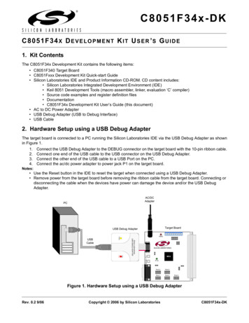
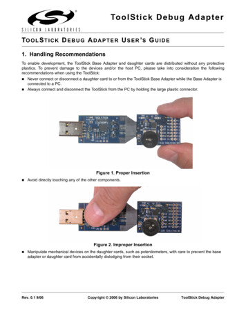
8-Bit USB Debug Adapter8-B I T USB D E B U G A DAPTER U SER ’ S G UIDE1. IntroductionThe 8-bit USB Debug Adapter (UDA) provides the interface between the PC’s USB port and the Silicon Labs 8-bittarget device’s in-system debug/programming circuitry. The 10-pin ribbon cable connects the adapter to the targetboard and the target device’s debug interface.Figure 1. 8-Bit USB Debug AdapterVisit www.silabs.com/8bit-uda for ordering information.2. Relevant DocumentationApplication notes can be found on the 8-bit MCU Application Notes web page: www.silabs.com/appnotes. AN124:Pin Sharing Techniques for the C2 Interface—Describes in detail the debug interface pinsharing feature for C2 devices, which enables debugging and use of the /RST and GPIO pins shared withC2CK and C2D. AN117: Using C8051Fxxx On-Chip Interface Utilities DLL—The SiUtil DLL discussed in this documentuses the USB Debug Adapter to program the memory space of C2 and JTAG devices. AN134: Multiple-Device JTAG Configuration in the Silicon Labs IDE—Configuration in the IDE andusing the USB Debug Adapter for devices in a JTAG chain.Rev. 0.3 1/15Copyright 2015 by Silicon Laboratories8-Bit USB Debug Adapter
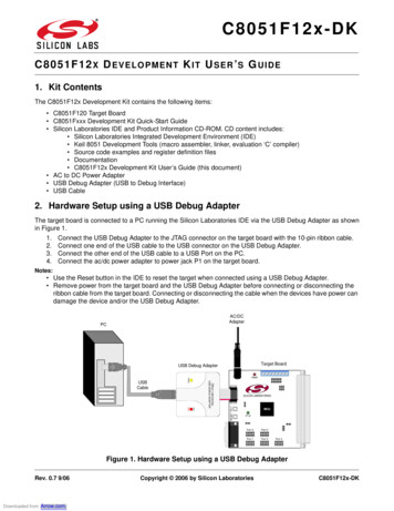
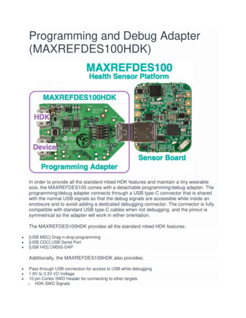
8-Bit USB Debug Adapter3. Pinout SpecificationThe 8-Bit USB Debug Adapter supports both Silicon Laboratories JTAG and C2 debug interfaces, and the adapteris powered from the USB connection to the PC. The UDA is also capable of providing power to the target device orother circuitry via pin 10 of the connector. Table 1 shows the pin definitions for the UDA keyed connector. The partnumber for the matching shrouded and keyed connector for a PCB is 2510-6002UB from 3M.The USB Debug Adapter can automatically change the communication voltage level based on the level detectedon pin 7 of the connector. As a result, this pin should be pulled high with a strong pull-up ( 1 kΩ) for noise immunitypurposes and not pulled down to ground.Notes: The USB Debug Adapter requires a target system clock of 32 kHz or greater. With the default settings, the USB Debug Adapter can supply up to 100 mA to a target system.Table 1. USB Debug Adapter Debug Connector Pin DescriptionsPin #DescriptionDetails1Not Connected2GND (Ground)3GND (Ground)4TCK / C2DJTAG TCK or C2 Data5TMS / C2CK pin shareJTAG TMS or C2 Clock pin sharing6TDO / C2D pin shareJTAG TDO or C2 Data pin sharing7TDI / C2CKJTAG TDI or C2 Clock signalThis pin is used by the UDA to sense and setthe logic voltage level. This pin should neverhave a pull-down to ground.8Not Connected9GND (Ground)10USB Power5 V power from the UDA1 3 5 7 92 4 6 8 10Figure 2. 8-Bit USB Debug Adapter Connector2Rev. 0.3
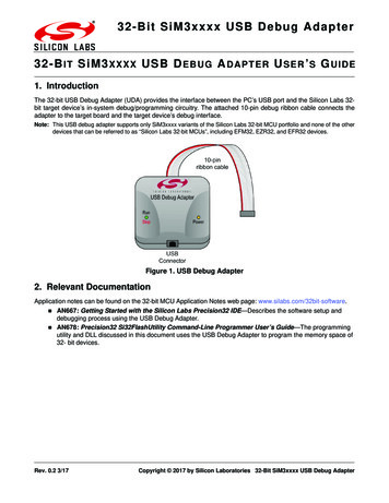
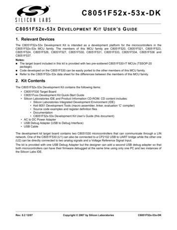
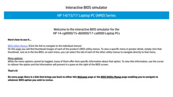
8-Bit USB Debug Adapter4. Minimum C2 Programming ConnectionsThe minimum required programming connections for the C2 interface are C2D (pin 4), C2CK (pin 7), and ground(pins 2, 3, or 9).5. Hardware Setup using a USB Debug AdapterConnect a target board to a PC running the Silicon Laboratories IDE via the USB Debug Adapter as shown inFigure 3.1. Connect the USB Debug Adapter’s 10-pin ribbon cable to the JTAG or Debug connector on the targetboard.2. Connect one end of a standard USB cable to the USB connector on the USB Debug Adapter.3. Connect the other end of the USB cable to a USB Port on the PC.4. Power the target board.Notes: Use the Reset button in the IDE to reset the target when connected using a USB Debug Adapter. Remove power from the target board and the USB Debug Adapter before connecting or disconnecting theribbon cable from the target board. Connecting or disconnecting the cable when the devices have power candamage the device and/or the USB Debug Adapter.132Figure 3. Hardware Setup using a USB Debug Adapter6. USB DriversThe USB Debug Adapter uses the Human Interface Device (HID) USB interface to communicate with the PC.Since most operating systems have this driver automatically built in, no drivers need to be installed to use the UDA.Rev. 0.33
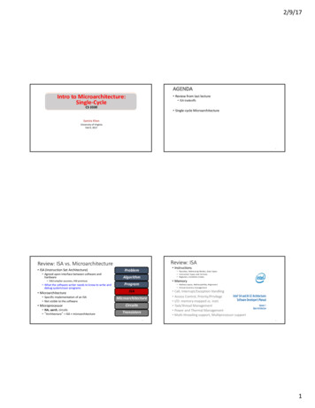
8-Bit USB Debug Adapter7. Software Setup using a USB Debug AdapterThe Silicon Laboratories Integrated Development Environment (IDE) along with other software tools are providedfor device development and debugging. The IDE is available for download from the Silicon Laboratories website(www.silabs.com/mcudownloads) and is also available on microcontroller development kit CD-ROMs.7.1. Configuring the USB Debug Adapter in the Silicon Labs IDEOnce the IDE has been installed and the hardware has been connected as shown in Section 5, follow the stepsbelow to built a project, connect and download to a target board using the USB Debug Adapter.1. Select Project Open Project. to open a previouslysaved project.2. Before connecting to the target device, severalconnection options may need to be set. Open theConnection Options window (shown in Figure 4) byselecting Options Connection Options. in the IDEmenu.3. Select USB Debug Adapter in the Serial Adaptersection.4. If more than one adapter is connected, choose theappropriate serial number from the drop-down list.5. Check the Power target after disconnect option if thetarget board is currently being powered by the USBDebug Adapter. The board will remain powered after asoftware disconnect by the IDE.6. Next, the correct Debug Interface must be selected.Check the Debug Interface corresponding to theSilicon Laboratories device on the target board.7. Once all the selections are made, click the OK button toclose the window.8. Click the Connect button in the toolbar or selectDebug Connect from the menu to connect to thedevice.9. Download the project to the target by clicking theDownload Code button in the toolbar.Figure 4. Connection Options10. Save the project when finished with the debug sessionto preserve the current target build configuration, editor settings and the location of all open debug views.To save the project, select Project Save Project As. from the menu. Create a new name for theproject and click on Save.4Rev. 0.3
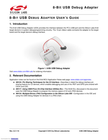
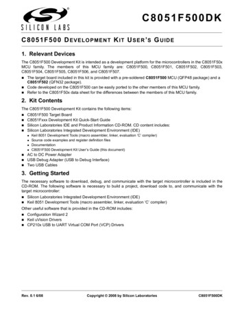
Figure 5. 8-Bit USB Debug Adapter Schematic (1 of 2)8-Bit USB Debug Adapter8. SchematicsRev. 0.35
Figure 6. 8-Bit USB Debug Adapter Schematic (2 of 2)8-Bit USB Debug Adapter6Rev. 0.3
Simplicity StudioOne-click access to MCU andwireless tools, documentation,software, source code libraries &more. Available for Windows,Mac and Linux!IoT Portfoliowww.silabs.com/IoTSW/HWQualitySupport and ualitycommunity.silabs.comDisclaimerSilicon Laboratories intends to provide customers with the latest, accurate, and in-depth documentation of all peripherals and modules available for system and software implementersusing or intending to use the Silicon Laboratories products. Characterization data, available modules and peripherals, memory sizes and memory addresses refer to each specificdevice, and "Typical" parameters provided can and do vary in different applications. Application examples described herein are for illustrative purposes only. Silicon Laboratoriesreserves the right to make changes without further notice and limitation to product information, specifications, and descriptions herein, and does not give warranties as to the accuracyor completeness of the included information. Silicon Laboratories shall have no liability for the consequences of use of the information supplied herein. This document does not implyor express copyright licenses granted hereunder to design or fabricate any integrated circuits. The products must not be used within any Life Support System without the specificwritten consent of Silicon Laboratories. A "Life Support System" is any product or system intended to support or sustain life and/or health, which, if it fails, can be reasonably expectedto result in significant personal injury or death. Silicon Laboratories products are generally not intended for military applications. Silicon Laboratories products shall under nocircumstances be used in weapons of mass destruction including (but not limited to) nuclear, biological or chemical weapons, or missiles capable of delivering such weapons.Trademark InformationSilicon Laboratories Inc., Silicon Laboratories, Silicon Labs, SiLabs and the Silicon Labs logo, CMEMS , EFM, EFM32, EFR, Energy Micro, Energy Micro logo and combinationsthereof, "the world’s most energy friendly microcontrollers", Ember , EZLink , EZMac , EZRadio , EZRadioPRO , DSPLL , ISOmodem , Precision32 , ProSLIC , SiPHY ,USBXpress and others are trademarks or registered trademarks of Silicon Laboratories Inc. ARM, CORTEX, Cortex-M3 and THUMB are trademarks or registered trademarks ofARM Holdings. Keil is a registered trademark of ARM Limited. All other products or brand names mentioned herein are trademarks of their respective holders.Silicon Laboratories Inc.400 West Cesar ChavezAustin, TX 78701USAhttp://www.silabs.com
Hardware Setup using a USB Debug Adapter Connect a target board to a PC running the Silicon Laboratories IDE via the USB Debug Adapter as shown in Figure 3. 1. Connect the USB Debug Adapter's 10-pin ribbon cable to the JTAG or Debug connector on the target board. 2. Connect one end of a standard USB cable to the USB connector on the USB Debug .