Transcription
the Technology Interface/Fall 2006KleinPLASTICS THERMOFORMING TOOL DESIGN:PLUG VS CAVITY MOLDSPeter W. Klein, Ph.D.klein@ohio.eduDepartment of Industrial TechnologyOhio UniversityABSTRACTOne of the most fundamental decisions when designing a mold for the plasticsthermoforming process is whether to use a plug (male) mold or a cavity (female) molddesign. This critical decision is often brushed over in the literature yet has the greatestsingle impact on part wall thickness and wall thickness variation. Other considerationswhen deciding on this fundamental design concept include location of thinnest crosssection, material shrink rates, a defect known as "webbing", and draw ratiodetermination. Given access to even the most basic thermoforming equipment, studentscan design a wide variety of molds to test and evaluate the difference between plug andcavity mold designs for similar part geometry. This paper will discuss such an activity.Specific Learning Objectives include:1) The student will understand the relationship between mold design, materialdeformation and part wall thickness.2) The student will understand the effect of materials shrink rates and part release fromthe mold.3) The student will be able to explain why parts produced with plug molds have less wallthickness variation than those produced with a cavity mold.4) The student will be able to calculate linear draw ratios on thermoformed parts andexplain the relationship of these ratios to wall thickness variation.I. INTRODUCTIONThermoforming is one of the fastest growing manufacturing processes in the plasticsindustry. It is a process in which thermoplastic sheet stock is re-shaped into a newgeometry using heat to soften (not melt) the sheet and forcing it into or onto a moldwhere it is cooled and "frozen" into the new geometry. The force may be in the form ofmechanical pressure, air pressure (compressed air), atmospheric pressure (drawing avacuum between the sheet and the mold) or any combination of these forces. The type offorce applied greatly effects the amount of deformation (stretching) possible as well asthe tool design. Regardless of the force applied to the sheet, the designer must decidewhether to use a positive configured mold (plug) or a negatively configured mold(cavity).1
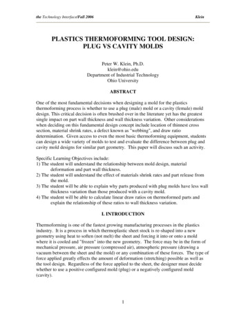
the Technology Interface/Fall 2006KleinII. MOLD DESIGN CONCEPT – PLUG VS CAVITYThe primary purpose of the mold used in the thermoforming process is to create thedesired part geometry. This is accomplished by shaping the sheet while it is at or abovethe forming temperature, holding the sheet in the new configuration and removingenough heat from the sheet to remain in the new geometry. The sheet is typically cooledto approximately 40 degrees Fahrenheit below the materials glass transition temperaturebefore removal from the mold [1]. The rate of cooling has a major impact on the cycletime which is a key cost factor. Remember: plastics are natural thermal insulators so ittakes time, therefore money, to increase the sheet temperature but also to remove the heatfrom the part before ejection from the mold. Since the entire sheet does not become theproduct, the excess material (known as "trim") must be removed. This may beaccomplished in secondary operations or during the molding process using moresophisticated, self-trimming molds.Since thermoforming is essentially a material deformation "stretching" process and thesheet will stretch at varying distances depending on the part geometry, there will beuneven part thicknesses. Thisis affected not only by partgeometry but also the processselected as well as the moldstyle, plug or cavity. A basicconcept to keep in mind is thatthe material quickly cools as ittouches the cold mold surfaceand the stretching ceases. Thefirst area of the sheet to makecontact with the mold will bethe thickest and the last area ofthe sheet to touch the mold willstretch the furthest andtherefore be the thinnest. Asillustrated in Figure 1, there isan almost inverse relationshipin wall thickness between partsof the same geometry whenformed in the cavity type moldon the left when compared tothose formed over a plug typemold on the right. [2]Fig.1 Cavity Vs Plug Mold(McConnell p.9-2)Both tool types are commonlyused in the thermoforming industry but clearly have an enormous impact on the thinninglocation of material due to stretching. Two important issues need to be noted in additionto the wall thickness differences. First, plug molded parts can be difficult to release.2
the Technology Interface/Fall 2006KleinPlastics expand when heated and shrinkwhen cooled. Some materials have ashrink rate as high as 5% when cooledfrom thermoforming temperatures asindicated in Figure 2. [3] Approximately50% of the shrinkage occurs while the partis in/on the mold. As the part cools over aplug mold, it shrinks and "grabs" the plugwhich can make part removal verydifficult. Increasing draft angles andmodifying the mold texture can improvepart removal; however it will not eliminatethis as a key issue for designers.Fig. 2 Typical Shrink Rates(McConnell p. 9-8)The second issue that needs to be noteddeals with a defect known as "webbing".This is a phenomenon that occurs whenthe heated material makes contact withitself while forming and permanentlybonds together causing a wrinkle. [4] Thisis a significant problem at corners whenthe part requires a deep draw as seen inFigure 3. Webbing only occurs when usinga plug mold.WebbingFig. 3 Webbing Defects(McConnell p. 5-9)III. LABORATORY ACTIVITYThe following lab activity is an excellentmethod for students to understand thedifferences in part thickness whendetermining whether to design a plug orcavity style mold. Several "test" moldshave been produced by students to use inthis activity.3
the Technology Interface/Fall 2006KleinFigure 4 shows two such molds to produce a flower pot. Both molds are made ofcomposites (fiberglass & polyester) and are mounted on a wooden vacuum basecompatible with the processing equipment to be used. The part geometry is very similarbetween mold types. The finished product is approximately 6"high and 6" in diameter. The thermoforming process in userequires a 12" X 12" sheet to be held in a clamping frame with a10" X 10" area available for forming.Each of the two sheets to be used in this activity is marked with a½" X ½" grid prior to forming as shown in Figure 5. This issimilar to an exercise in Richardson's' book [5].Cavity Mold ExampleFigure 6 shows the cavity mold in position on thethermoformer. The wooded box beneath themold is a vacuum box which is connected to avacuum surge tank.Figure 7 shows the heated sheet in place over themold ready to be formed.4
the Technology Interface/Fall 2006KleinFigure 8 shows the sheet being drawn into themold. (The material is actually forced into themold with atmospheric pressure.) Note the gridpattern! The area of the sheet that first touchesthe mold has not deformed. The entire part wasproduced by the material within the cavity area.Figure 9 shows the part and the "trim"; again notethe grid pattern and the degree of deformation.Plug Mold ExampleFigure 10 shows the plug configured mold inplace on the thermoformer.5
the Technology Interface/Fall 2006KleinFigure 11 shows the plug mold being raised intothe heated sheet mechanically stretching thematerial. This process is known as drapeforming. Note the deformation on the grid!Figure 12 shows the sheet being drawn over theplug mold where it will cool. Note the gridpattern and the area of deformation whichextends to the clamping frame. Also note thatthe bottom of the pot (the area which firsttouched the mold) has almost no deformation,thus retaining its original sheet thickness.Figure 13 shows the part and "trim" afterremoval from the thermoformer. Note thedeformation and the quality defect known as"webbing". This is the wrinkled areas on thesides of the pot where it meets the "trim".6
the Technology Interface/Fall 2006KleinMold Design ComparisonFigures 14 & 15 show the cavity and plug formedunits side by side for comparison. Thedeformation location and degree are quiteobvious. Note the grid lines and the specific areasof greatest deformation between the cavitymolded part on the left and the plug molded parton the right. The bottom of the cavity molded potis very thin due to extreme stretching while thebottom of the plug molded pot is nearlyunchanged from the original sheet thickness.FiguresFigures 16 & 17 show the part (flower pots)removed from the "trim". Note the significantdifference in material deformation on the potbottoms!Figure 18 shows wall thickness dimensions in.000" for the cavity mold. The starting sheetthickness was .022". The thinnest location of.001" represents 4.55% of the originalthickness.7
the Technology Interface/Fall 2006KleinFigure 19 shows wall thickness dimensionsin .000" for the plug mold. The startingsheet thickness was .022". The thinnestlocation of .008" represents 36.36% of theoriginal thickness.Draw RatiosThere are several Draw Ratios that can be used to analyze parts. These include ArealDraw Ratios, Linear Draw Ratios and Height-to-Dimension Ratios. Each has advantagesand is only grossly representative of sheet thinning, however they can be excellentinstructional tools for comparing part designs and processes. The following activity canbe used with the previous plug and cavity produced parts to better understand thethermoforming process. For simplicity, Linear Draw Ratio is used. Linear Draw Ratio isthe ratio of the length of a line drawn on the sheet prior to forming compared to thelength of the same line after forming. Only the line length in the forming area is usedtherefore the length varies between plug and cavity molds. The forming area of a plugmold includes the distance between clamping frames while the forming area of a cavitymold includes only the width of the cavity opening. [6] The previously molded part isillustrated in the following calculations.8
the Technology Interface/Fall 2006KleinCavity Mold Linear Draw RatioLength of line prior to forming 6"Length of line after forming 6" 3" 6" 15"Linear Draw Ratio 15/6 2.5In other words, the sheet would stretch 2.5 times itsoriginal length.Plug Mold Linear Draw RatioLength of line prior to forming 10"Length of line after forming 2" 6" 3" 6" 2" 19"Linear Draw Ratio 19/10 1.9In other words, the sheet would stretch 1.9 times itsoriginal length.IV. CONCLUSIONThermoforming is essentially a stretching process in which thermoplastic sheet stock isheated to its softening temperature, stretched into a new shape and frozen when the heatis removed. There are many variables in the process including incoming sheet quality,part geometry, forming force and mold type. This paper specifically discussed the impactof mold type on the wall thickness variation within a product. Plug and cavity moldsyielding similar parts were built and tested. Both mold types are used extensively andeach has advantages and disadvantages particularly in the location of wall thicknessvariation. As illustrated in the test parts as well as the linear draw ratio calculations, anadvantage of plug configured molds is that wall uniformity is typically better becausematerial has a lower draw ratio. [7] However plug molds have particular problems withpart release and webbing which are not found when using cavity molds. The labactivities are an excellent method for designers to confirm the impact of mold type onwall thickness. Simple test molds of varying shapes are often created to simulate drawratios to identify problems before permanent molds are constructed.9
the Technology Interface/Fall 2006KleinREFERENCES[1] Throne, James, Thermoforming, p.120, 1987.[2] McConnell, William K., Thermoforming. Society of Plastics Engineers SeminarNotebook, p.9-2, Jan. 1995.[3] McConnell, William K., Thermoforming. Society of Plastics Engineers SeminarNotebook, p.9-8, Jan. 1995.[4] McConnell, William K., Thermoforming. Society of Plastics Engineers SeminarNotebook, p.5-9, Jan. 1995.[5] Richardson, Terry L. & Lokensgard, Eric, Industrial Plastics: Theory andApplications, 3rd edition, p.255, 1997.[6] Throne, James, Understanding Thermoforming, p.85, 1999.[7] Strong, Brent, Plastics Materials and Properties, 3rd edition, p.567, 2006.10
One of the most fundamental decisions when designing a mold for the plastics thermoforming process is whether to use a plug (male) mold or a cavity (female) mold design. This critical decision is often brushed over in the literature yet has the greatest single impact on part wall thickness and wall thickness variation. Other considerations