Transcription
10623 Roselle Street, San Diego, CA 92121 (858) 550-9559 contactus@accesio.com www.accesio.comFax (858) 550-7322USB 16-CHANNEL HIGH-SPEEDDIGITAL INPUT/OUTPUT 6AUSER MANUALMUSB-DIO-16H.B1d
NoticeThe information in this document is provided for reference only. ACCES does not assume any liabilityarising out of the application or use of the information or products described herein. This document maycontain or reference information and products protected by copyrights or patents and does not conveyany license under the patent rights of ACCES, nor the rights of others.IBM PC, PC/XT, and PC/AT are registered trademarks of the International Business MachinesCorporation.Printed in USA. Copyright 2008 by ACCES I/O Products, Inc. 10623 Roselle Street, San Diego, CA92121. All rights reserved.WARNING!!ALWAYS CONNECT AND DISCONNECT YOUR FIELD CABLING WITHTHE COMPUTER POWER OFF. ALWAYS TURN COMPUTER POWEROFF BEFORE INSTALLING A BOARD. CONNECTING ANDDISCONNECTING CABLES, OR INSTALLING BOARDS INTO ASYSTEM WITH THE COMPUTER OR FIELD POWER ON MAY CAUSEDAMAGE TO THE I/O BOARD AND WILL VOID ALL WARRANTIES,IMPLIED OR EXPRESSED.2USB-DIO-16H User Manual
WarrantyPrior to shipment, ACCES equipment is thoroughly inspected and tested to applicable specifications.However, should equipment failure occur, ACCES assures its customers that prompt service andsupport will be available. All equipment originally manufactured by ACCES which is found to be defectivewill be repaired or replaced subject to the following considerations.Terms and ConditionsIf a unit is suspected of failure, contact ACCES' Customer Service department. Be prepared to give theunit model number, serial number, and a description of the failure symptom(s). We may suggest somesimple tests to confirm the failure. We will assign a Return Material Authorization (RMA) number whichmust appear on the outer label of the return package. All units/components should be properly packedfor handling and returned with freight prepaid to the ACCES designated Service Center, and will bereturned to the customer's/user's site freight prepaid and invoiced.CoverageFirst Three Years: Returned unit/part will be repaired and/or replaced at ACCES option with no chargefor labor or parts not excluded by warranty. Warranty commences with equipment shipment.Following Years: Throughout your equipment's lifetime, ACCES stands ready to provide on-site or inplant service at reasonable rates similar to those of other manufacturers in the industry.Equipment Not Manufactured by ACCESEquipment provided but not manufactured by ACCES is warranted and will be repaired according to theterms and conditions of the respective equipment manufacturer's warranty.GeneralUnder this Warranty, liability of ACCES is limited to replacing, repairing or issuing credit (at ACCESdiscretion) for any products which are proved to be defective during the warranty period. In no case isACCES liable for consequential or special damage arriving from use or misuse of our product. Thecustomer is responsible for all charges caused by modifications or additions to ACCES equipment notapproved in writing by ACCES or, if in ACCES opinion the equipment has been subjected to abnormaluse. "Abnormal use" for purposes of this warranty is defined as any use to which the equipment isexposed other than that use specified or intended as evidenced by purchase or sales representation.Other than the above, no other warranty, expressed or implied, shall apply to any and all suchequipment furnished or sold by ACCES.3USB-DIO-16H User Manual
TABLE OF CONTENTSChapter 1: Introduction . 5Features . 5Applications . 5Functional Description . 5Figure 1-1: Block Diagram . 6High-Speed Digital I/O . 6Digital I/O . 6Ordering Guide . 7Model Options . 7Included with your board . 7Optional accessories . 7Chapter 2: Installation . 8Software CD Installation . 8Hardware Installation . 8NOTES ABOUT HAND-SHAKING: . 8Chapter 3: Hardware Details . 9Option Selection . 9Figure 3-1: Option Selection Map . 9USB Connector (P1) . 10Embedded USB Connector (P4) . 10LED. 10DC Power Jack (Optional). 1068-PIN I/O Connector (J1) . 10Chapter 4: USB Address Information . 11Chapter 5: Programming . 12Chapter 6: Connector Pin Assignments . 13TABLE 6-1: Connector Pin Assignments . 13TABLE 6-2: Detailed Pin Descriptions . 14Chapter 7: Specifications . 15TTL High-Speed Digital I/O’s (LVTTL Optional) . 15TTL Standard Digital I/O’s (LVTTL Optional) . 15Internal Clock . 15Data FIFOs . 15Environmental . 15Power . 15Appendix A: Theory of Operation . 17Output . 17Input . 18Paired Operation: . 18Warning about bus contention . 19Appendix B: Proposed I/O Negotiation Algorithms . 20Hard Coded (Embedded) Configuration . 21Handshaking Used (Known Slave) . 23Handshaking Used (Known Master) . 25Customer Comments . 264USB-DIO-16H User Manual
Chapter 1: IntroductionThis USB based Data Acquisition Module is an ideal solution for adding portable, easy-to-installhigh-speed digital input/output to any computer with a USB port. The unit is a USB 2.0 highspeed device and requires a USB 2.0 port to function.Features 16 high-speed digital I/O lines featuring continuous throughput of 16MB/sCapable of 80MB/s burstsFlexible internal or external synchronous clocking and handshaking capabilities18 additional digital I/O linesAll output lines buffered with 24mA sink/source current capabilitiesStandard 68-pin High Density connectorCustom high-speed function driverPC/104 module size and mounting compatibilitySmall (4" x 4" x 1.25") rugged industrial enclosureMiniature USB connector for embedded applicationsApplications Digital ImagingEmbedded data acquisitionData TransferEducation/LaboratoryFunctional DescriptionThis product is a USB based digital board with16 high-speed digital inputs/outputs capable ofup to 8MHz (16MegaByte) continuous scanning and up to 40MHz (80MegaByte) bursts. Fourmodel versions are available; an input/output unit (USB-DIO-16A), an input only unit (USBDI16A), an output only unit (USB-DO16A) all with 4k word FIFOs, and an input/output unit withexpanded 64k word FIFO (USB-DIO-16H).The 16 high-speed lines are TTL-compatible digital inputs/outputs with high-currentcapabilities. The programmable clock facilitates capability of 1k-40MHz transfers or the usermay choose to use their own external clock. All clock signals are provided on the connectorand are synchronous. In addition to the 16 high-speed inputs/outputs there are 18 standarddigital I/O channels configurable as 4 separate ports for input or output. Power is supplied tothe board via the USB cable; for higher current capabilities, external 9V AC/DC power adaptermay be used. The I/O wiring connections for this unit are via an industry standard 68-pin SCSIconnector. For external circuits, fused 5VDC (see note) power is available at the connectorbased on a hardware jumper selection made by the user. This resettable fuse is rated at 0.5A.Note: Anywhere 5VDC is referred to in this manual with the exception of USB powerrequired can be substituted with 3.3VDC for the LVTTL option.Pull-ups to 5VDC on the board assure that I/O lines are at a known state at power-up until theboard is initialized by system software.A type B USB connector is used on all models which features a high retention design thatcomplies with the class 1, Div II minimum withdrawal requirement of over 3 pounds of force.5USB-DIO-16H User Manual
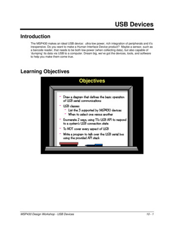
This connector has an orange color-coded insulator to differentiate it from standard USBconnectors.The complete unit is designed for use in rugged industrial environments but is compact enoughto fit nicely onto any desk or testing station. The board is PC/104 sized (3.550 by 3.775 inches)with mounting capability and ships standard inside a steel powder-coated enclosure with ananti-skid bottom.Figure 1-1: Block DiagramHigh-Speed Digital I/OThere is one 16-bit high-speed Digital I/O bus (DATA I/O0 to DATA I/O15) available on thisboard. This bus can be configured for either inputs/outputs depending on the model ordered.These ports can also be tri-stated. Each DIO line is buffered and capable of sourcing 24mA orsinking 24mA. Be sure to consult the Power section for total power limitations beforeoperation. By default the DIO lines are pulled up with a 10KΩ resistor to 5V.Digital I/OThere are 18 additional Digital I/O lines (Port A, Port B, Port C and Port D) available on thisboard. Each port can be configured for either input or output however Port C and Port D arealways configured in opposite directions of each other. These ports can also all be tri-stated.Port A is an 8-bit Port, Port B is a 4-bit Port, and Ports C and D are each 3-bits. Each DIO lineis buffered and capable of sourcing/sinking 24mA. Be sure to consult the Power section fortotal power limitations before operation. By default the DIO lines are pulled up with a 10KΩresistor to 5V.6USB-DIO-16H User Manual
Ordering GuideUSB-DI16A - 16 High-Speed Digital Inputs ONLY w/4K word FIFO and 18 standard I/OsUSB-DO16A - 16 High-Speed Digital Outputs ONLY w/4K word FIFO and 18 standard I/OsUSB-DIO-16A - 16 High-Speed Digital Inputs OR Outputs w/4K word FIFO and 18 standard I/OsUSB-DIO-16H - 16 High-Speed Digital Inputs OR Outputs with 64K word FIFO and 18 standard I/OsModel Options -LV-P-OEM-DIN-T-S0xLVTTL for 3.3V applicationsExternal AC/DC adapter (power jack/regulator installed)Board only (no enclosure)DIN rail mounting provisionExtended Temperature Operation (-40 to 85 C)“x” special number designatorexamples include 16K FIFO, 32K FIFO, 64K FIFO, conformal coating, etc.Included with your boardThe following components are included with your shipment. Please take time now to ensurethat no items are damaged or missing.1.2.3.4.USB Module (unit installed in labeled enclosure)6’ USB cableSoftware Master CD (PDF user manual installed with product package)Printed USB I/O Quick-Start GuideOptional accessories C68PS18L STB-68 CUSB-EMB-6 - MP104-DIN -68-Pin SCSI 18” shielded cable with one-touch latchesScrew Terminal Board (mounted on standoffs)6’ USB Cable with type A connector to mini USB connector forembedded applications (mates with P4 on the board)DIN rail mounting provision7USB-DIO-16H User Manual
Chapter 2: InstallationSoftware CD InstallationThe software provided with this board is contained on one CD and must be installedonto your hard disk prior to use. To do this, perform the following steps asappropriate for your operating system. Substitute the appropriate drive letter for yourdrive where you see D: in the examples below.WIN98/Me/2000/XP/2003a.b.c.Place the CD into your CD-ROM drive.The CD should automatically run the install program. If the install program doesnot run, click START RUN and type , click OK or press .Follow the on-screen prompts to install the software for this board.LINUXa.Please refer to linux.htm on the CD-ROM for information on installing underLinux.Hardware InstallationPlease install the software package before plugging the hardware into the system. Theboard can be installed in any USB 2.0 port. Please refer to the USB I/O Quick StartGuide which can be found on the CD, for specific, quick steps to complete the hardwareand software installation.NOTES ABOUT HAND-SHAKING:In order to transmit data you MUST ground the pulled-up /TX EN (Transmit Enable)signal at PIN 19.In order to receive data you MUST ground the pulled-up /RX EN (Receive Enable)signal at PIN 17.Please note: if connecting two USB-DIO-16H family devices together with a standard1-to-1 cable these signals are correctly connected to RX AF (Receive FIFO AlmostFull) and TX FE (Transmit FIFO Empty), respectively. If your application supports thiskind of handshaking, connect those signals instead of simply grounding these pins.8USB-DIO-16H User Manual
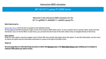
Chapter 3: Hardware DetailsOption SelectionYou may also refer to the setup program installed from the CD provided with the board. Thereare two user selectable hardware options available. One is VUSB vs. VEXT which selectsbetween USB powered or externally powered. The other is fused 5V output on I/O connectorpin 34 or NC (no connect).Figure 3-1: Option Selection Map9USB-DIO-16H User Manual
USB Connector (P1)The USB connector available via the outside of the enclosure is a Type B and mates with thesix foot cable provided. The USB port provides communication signals along with 5 VDCpower. The board can be powered from the USB port or an external power supply can be used.Embedded USB Connector (P4)In applications where the OEM (board only, no enclosure) version of this board is used, it maybe desirable to use the miniature USB connector onboard, which is next to and in parallel withthe Type B connector.LEDThe LED on the front of the enclosure is used to indicate power and data transmissions. Whenthe LED is in an illuminated steady green state, this signifies that the board is successfullyconnected to the computer and has been detected and configured by the operating system.When the LED flashes continuously, this signifies that there is data being transmitted over theUSB bus.FUSED 5VThe fused 5V jumper is located near J1. When installed in the 5V position the fused 5V willbecome available on pin 34 of J1. The fuse is rated at 500mA and is self resetting. If thejumper is installed in the NC position or is not installed, pin 34 is a no connect.DC Power Jack (Optional)Please note, not all boards will contain this option. This is an option for high currentapplications when more current is needed than what your computer can provide on the USBport (typically 500 mA). The DC jack has a 2.00mm post on board and is designed to be usedwith the 9 VDC AC/DC external power supply that ships with this option. The voltage regulatoron board regulates the 9 VDC and provides 5 VDC to the onboard circuitry. When usingexternal power, switch the jumper located near the USB connector to VEXT, otherwise whenthe jumper is in the VUSB position current is drawn from the USB port (please consult theoption selection map for a visual reference).If the board will be ordered as an OEM-P option (board only with external power) then thepower input will be reconfigured (by removing the voltage regulator to prevent damage duringshipment and while handling) such that the external power supply should then provide aregulated 5 VDC to the power jack instead of the standard 9 VDC.68-PIN I/O Connector (J1)The I/O is accessed via a 68-pin female SCSI Pin in Socket type connector with one-touch locklatches. Detailed pin assignments are listed in chapter 6, as well as a handy reference of pinfunctions printed on the enclosure label.10USB-DIO-16H User Manual
Chapter 4: USB Address InformationUse the provided driver to access the USB board. This driver will allow you to determine howmany supported USB devices are currently installed, and each device’s type. This informationis returned as a Vendor ID (VID), Product ID (PID) and Device Index.The VID for all four models is “0x1605", and the PID is unique for each model as D PID PID PID sing the VID and PID as demonstrated in our sample programs will allow you to determinehow many of these devices are attached to your system and the system-assigned "DeviceIndex" for each of those devices. If you have more than one of any given PID you mayencounter the need to "tell them apart" reliably, as the system-assigned Device Index is a plugand-play value that changes as devices are plugged into and removed from your system.In order to enable you to reliably tell devices with the same VID/PID apart we haveimplemented a user-accessible region of the onboard EEPROM. Refer to the SoftwareReference Manual for more information about the "CustomEEPROMRead" and"CustomEEPROMWrite" function for details. In general, you can simply write a unique value toa byte of EEPROM, then your software can track changes to the Device Index units by thisvalue.In addition, the user-accessible EEPROM is hundreds of bytes long, enabling numerousoptional functionality of your choice.See the Software Reference Manual, installed on your system along with the board supportpackage, for more information.11USB-DIO-16H User Manual
Chapter 5: ProgrammingThe driver software provided with the board uses a 32-bit .dll front end compatible with anyWindows programming language. Samples provided in Borland C Builder, Borland Delphi,Microsoft Visual Basic, and Microsoft Visual C demonstrate use of the driver.Many functions are provided by the driver in Windows.For detailed information on each function refer to the PDF Software Reference Manual locatedin the Win32 directory for this board.12USB-DIO-16H User Manual
Chapter 6: Connector Pin AssignmentsThe I/O connector is a 68-pin Type 2 SCSI female, right-angle type with quick-release “onetouch” locking latches, which protrudes through a cutout in the module’s enclosure.PinSignal NamePinSignal Name1DATA I/O 035GND2DATA I/O 136GND3DATA I/O 237GND4DATA I/O 338GND5DATA I/O 439GND6DATA I/O 540GND7DATA I/O 641GND8DATA I/O 742GND9DATA I/O 843GND10DATA I/O 944GND11DATA I/O 1045GND12DATA I/O 1146GND13DATA I/O 1247GND14DATA I/O 1348GND15DATA I/O 1449GND16DATA I/O 1550GND51GND52GND53GND17181920Input Mode: /RX ENOutput Mode: TX FEInput Mode: RX CLKOutput Mode: TX ACKInput Mode: RX AFOutput Mode: /TX ENInput Mode: RX ACKOutput Mode: TX CLK54GND21DOI D055GND22DIO C056GND23DIO C157GND24DIO C258GND25NC59GND26DIO B060DIO A027DIO B161DIO A128DIO B262DIO A229DIO B363DIO A330DOI D164DIO A431DOI D265DIO A532NC66DIO A633NC67DIO A734FUSED 5V (jumper selected)68GNDTABLE 6-1: Connector Pin Assignments13USB-DIO-16H User Manual
NameI/ODATA I/O 0 through 15I/O/RX ENITX FEORX CLKITX ACKORX AFO/TX ENIRX ACKOTX CLKIGNDN/ADIO A0 through A7I/ODIO B0 through B3I/ODIO C0 through C2I/ODOI D0 through D2O/IFREQUENCY OUTOFUSED 5VON/CXDescription16-Bit Data Bus Input/Output Bit 0 through 15 (all pulled up through10K ohms to 5V).Receive Enable (active-low): When /RX EN is LOW, data is written intothe FIFO on every LOW-to-HIGH transition of either RX CLK or from theinternal clock on board. When /RX EN is HIGH, the FIFO holds theprevious data. Data will not be written into the FIFO if it is full.Transmit FIFO Empty (active-high): When TX FE is HIGH, the FIFO isempty and further data reads from the output are inhibited. When TX FEis low, the FIFO is not empty. TX FE is synchronized to TX ACK.External Receive Clock: When /RX EN is LOW, data is written into theFIFO on a LOW-to-HIGH transition of RX CLK, if the FIFO is not full. Thissignal is used when providing an external clock and not using the internalclock on board which is programmable from 1K-40MHz.Transmit Acknowledge Clock: When TX ACK transitions from LOW-toHIGH data can be read from the board. TX ACK is the delayed clockused to read data out of the FIFO.Receive Almost Full Flag (active-high): When RX AF is HIGH, theFIFO is 127 words from full.Transmit Enable (active-low): When /TX EN is LOW, data is read fromthe FIFO on every LOW-to-HIGH transition of TX CLK or from theinternal clock on board. When /TX EN is HIGH, the output register holdsthe previous data. Data will not be read from the FIFO if the TX FE isHIGH.Receive Acknowledge Clock: When RX ACK transitions from LOW-toHIGH data has been read into the board. RX ACK is the delayed clockused to read data into the FIFO.External Transmit Clock: When /TX EN is LOW, data is read from theFIFO on a LOW-to-HIGH transition of TX CLK, if the FIFO is not empty.This signal is used when providing an external clock and not using theinternal clock on board which is programmable from 1K-40MHz.GroundPort A Digital I/O Bit 0 through Bit 7(all pulled up through 10K ohms to 5V)Port B Digital I/O Bit 0 through Bit 3(all pulled up through 10K ohms to 5V)Port C Digital I/O Bit 0 through Bit 2(all pulled up through 10K ohms to 5V) The direction of this port is theinverse of Port D’s direction.Port D Digital O/I Bit 0 through Bit 2(all pulled up through 10K ohms to 5V) The direction of this port is theinverse of Port C’s direction, which is why we named them O/I Bits.Optional Signal / ReservedJumper Selectable 500mA Fused 5V. This is an output ONLY! Do notapply 5V to this pin.Not ConnectedTABLE 6-2: Detailed Pin Descriptions14USB-DIO-16H User Manual
Chapter 7: SpecificationsTTL High-Speed Digital I/O’s (LVTTL Optional)LinesContinuous ThroughputInput voltageInput currentOutput voltageOutput current16, programmable as all inputs or all outputs(“16A” or “16H” only)8MHz or 16MB/s maximumLogic low:-0.5 to 0.8 VDCLogic high:2.0 to 5.0 VDC 20μA(max)Logic low:0.44 VDC (max)Logic high:4.4 VDC (min)Logic low:24 mA (max) sinkLogic high:24 mA (max) sourceTTL Standard Digital I/O’s (LVTTL Optional)LinesInput voltageInput currentOutput voltageOutput current18, programmable as inputs or outputs as 4 Ports (A-D)Logic low:-0.5 to 0.8 VDCLogic high:2.0 to 5.0 VDC 20μA(max)Logic low:0.44 VDC (max)Logic high:4.4 VDC (min)Logic low:24mA (max) sinkLogic high:24mA (max) sourceInternal ClockFrequency Range1k - 40MHzExternal ClockFrequency40 MHz maximumData -DI16A:USB-DO16A:128 kByte8 kByte8 kByte8 kByteEnvironmentalOperating TemperatureStorage TemperatureHumidityBoard DimensionsBox Dimension:0 to 70 C, optional -40 to 85 C-40 to 105 C5% to 95% RH, without condensationPC/104 format, 3.550” by 3.775” and mounting holes4.00 x 4.00 x 1.25 inchesPowerPower requiredAuxiliary power output 5V at 100mA with no load typical1 5VDC via 0.5A resettable fuse at connector (jumper selectable) 3.3VDC via 0.5A resettable fuse (with LVTTL Option)15USB-DIO-16H User Manual
Power ModesUSB portExternal supply 5VDC provided via USB bus up to 500mA**Optional external power adaptor @ 9VDC through DC power jackand on-board regulator to produce 5VDCFactors that affect the amount of current required by this module include any power drawn fromthe auxiliary 5VDC through the resettable fuse, as well as any digital outputs that are wired tosource current to external circuits (where the other side of the load is tied to ground / return).Any digital outputs wired to sink current to external loads will not necessarily increase thecurrent drawn by the module, unless the positive side of the load is fed from the auxiliary 5VDC previously mentioned.** If using more than a total of 500mA, use optional 9 VDC (on board voltage regulator outputs 5 VDC to card) external power supply and remove VUSB jumper and place jumper on VEXT.Then plug in external power before plugging into USB port. This option will give you a total of1000mA available. If using the OEM board with the power option (OEM-P) then use aregulated 5 VDC external supply as the on-board regulator will not be installed.1USB 2.0 spec defines a device in terms of a unit load. A unit load is defined to be 100mA.Devices drawing an absolute maximum of one unit load are considered to be low-powered anddevices drawing an absolute maximum of five unit loads are considered to be high-powered.Because this spec is not strictly adhered to, it is best to verify the USB port's power capabilitiesbefore operation. This card, according to the USB 2.0 spec, is a high powered device. Anoptional external power supply can be ordered if the USB port cannot support high powereddevices.16USB-DIO-16H User Manual
Appendix A: Theory of OperationUnlike common 8255 based digital I/O, this unit provides a true synchronous, high-speed,buffered digital bus.What does this mean for you? Well, you should understand the available, and sometimesnecessary, handshaking signals on the connector associated with all that power.You may wish to refer to the Block Diagram while reading this appendix.In general, the entire high speed bus on any given unit can be treated as a single FIFO. Let’sdiscuss only the output board (or the I/O board being used in output mode) for a moment:OutputFour signals accompany the data on the output board: TX ACK, TX FE, /TX EN, andTX CLK.It is convenient to think of these four signals in two pairs, “block” and “per word” handshakinglines.TX FE and /TX EN are the “block” handshaking lines. TX FE indicates the FIFO is Empty (itgoes high when the FIFO is empty). /TX EN indicates the receiving device wants to stop amoment; we’ll get into why it might want to stop when we discuss the receive mode. Note,pulling /TX EN LOW indicates GO. You need to raise the line HIGH to STOP transmission.TX CLK and
This USB based Data Acquisition Module is an ideal solution for adding portable, easy-to-install high-speed digital input/output to any computer with a USB port. The unit is a USB 2.0 high-speed device and requires a USB 2.0 port to function. Features 16 high-speed digital I/O lines featuring continuous throughput of 16MB/s