Transcription
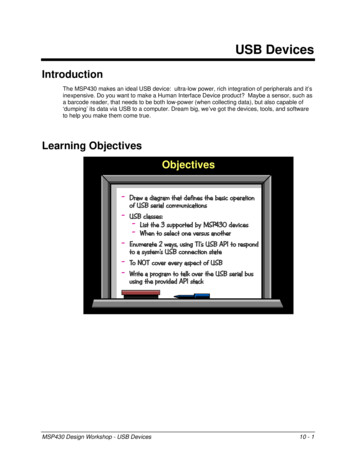
USB DevicesIntroductionThe MSP430 makes an ideal USB device: ultra-low power, rich integration of peripherals and it’sinexpensive. Do you want to make a Human Interface Device product? Maybe a sensor, such asa barcode reader, that needs to be both low-power (when collecting data), but also capable of‘dumping’ its data via USB to a computer. Dream big, we’ve got the devices, tools, and softwareto help you make them come true.Learning ObjectivesObjectives- Draw a diagram that defines the basic operationof USB serial communications- USB classes:- List the 3 supported by MSP430 devices- When to select one versus another- Enumerate 2 ways, using TI’s USB API to respondto a system’s USB connection state- To NOT cover every aspect of USB- Write a program to talk over the USB serial bususing the provided API stackMSP430 Design Workshop - USB Devices10 - 1
IntroductionChapter TopicsUSB Devices . 10-1Introduction . 10-1What is USB? . 10-3MSP430's USB Support . 10-7USB Fees . 10-13How USB Works . 10-15Pipes and Endpoints . 10-16USB Transfer Types. 10-19The USB Frame . 10-20Descriptions and Classes. 10-22Quick Overview of MSP430’s USB Stack . 10-28ABC’s of USB . 10-31A. Plan Your System . 10-31B. Connect & Enumerate . 10-32C. Managing my App & Transferring Data . 10-34Final Thoughts . 10-37Lab Exercise . 10-3910 - 2MSP430 Design Workshop - USB Devices
What is USB?What is USB?Universal Serial Bus (USB) is just that, a universal serial connection between a “Host” and“Device”. It has taken the place of many synchronous and asynchronous serial bus connectionsin systems such as personal computers.In the case of USB, the host manages all transfers, whether moving data to or from the host –often this is called a master/slave architecture, where the host is the bus master. At a minimum,there needs to be one host and one device.MSP430 Design Workshop - USB Devices10 - 3
What is USB?But USB supports many more than just a single device, the standard can actually support up to127 different devices. Commonly, systems with multiple devices use hubs as interconnectionpoints between the host and devices – which results in a star arrangement.Each type of device is distinguished using Vendor and Product ID (VID/PID). The combination ofVID and PID allows a host to identify the type of device that is connected and manage the pointto-point communications with it – in most cases, this requires the host to load the appropriatedrivers required to talk with that specific type of device. (We’ll discuss this is greater detail later inthe chapter.)10 - 4MSP430 Design Workshop - USB Devices
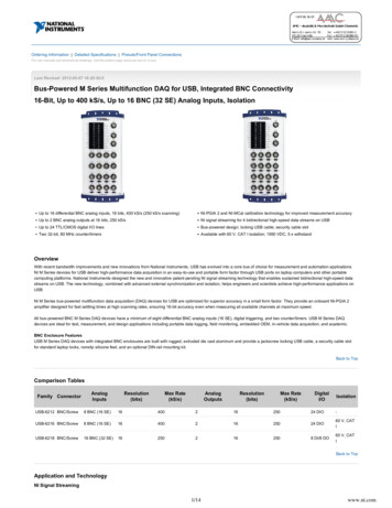
What is USB?The Universal Serial Bus protocol has gone through a few versions over time. Back in 1995 USBrevision 1.1 was released. This version provided separate host and device connectors along withsupporting two different speeds: Low speed moved data at speeds up to 1.5Mpbs (megabits-persecond); while Full speed provided data rates up to 12Mbps.USB StandardsVersionYearSpeedsPowerAvailaNleNotesUSB 1B1199D1½ MNps (Low)12 MNps (Full)–Host & Gevice connectorsUSB 2B020001½ MNps (Low)12 MNps (Full)480 MNps (HigO)D00 mA Backward compatiNlewitO USB 1B1 Added On-tOe-Go (OTG)20081½ MNps (Low)12 MNps (Full)480 MNps (HigO)4B8 GNps (Super)900 mA Backward USB 2B0compatiNility Full-duplex Power mgmt featuresUSB 3B0aSt430 USB teripheral Supports USB 2.0 standardFull speed USB device (12abps)Device onlyNote: Look at TI’s TivaC processors if you need host, device or OTG supportIn 2000, USB 2.0 was released as an upgrade to USB 1.1. Along with Low and Full speeds, amuch faster High 480Mbps rate was added. Other major additions to the standard included apower supply of 500 mA provided from the USB cable, as well as capability for advanced devicesto switch between Host and Device modes – called On-The-Go (OTG) mode. The OTG feature ishandy in some applications where a product might have to be a Device or a Host depending uponwhat it is connected to.The MSP430’s USB port supports the USB 2.0 standard, but only operating at the Full rate.(Seeing that the fastest MSP430 devices only run up to 25MHz, it’s not hard to wonder why theycannot support the 480Mbps rate.) Additionally, since the MSP430 doesn’t provide Host support,it therefore does not provide the OTG Host/Device switching feature.Hint:If your product needs Host and or OTG support, you may want to check out TI’s Tiva-Cline of ARM Cortex M4F processors.Just a few years ago, in 2008, USB added the 3.0 revision. While once again backwardcompatible to USB 1.1 and USB 2.0, the new revision added an additional Super 4.8Gpbs rate. Italso included full-duplex operation, a higher power sourcing availability of 900 mA as well asother power-management features. While this is quite advantageous for many types of endapplications – such as hard disk drives, high-end imaging systems (i.e. scanners), and such – it’soverkill for many other systems, where low power and cost are primary directives.MSP430 Design Workshop - USB Devices10 - 5
What is USB?Bus standards, such as USB, contain a variety of layers. While these physical and dataspecifications are important, exploring them in great detail is outside the scope of this chapter.On the following slide, we’ll introduce a couple basic features of the physical layer – that is, of theUSB cable. Later on in the chapter, we will discuss some of the details regarding data andsoftware layers.Bottom Line: We have tried to approach USB, in this chapter, from a pragmatic perspective. Thatis, rather than examining the details of the specification, we want to figure out how to use TI’sdevices and tooling in order to just get something running.USB Physical LayerY Four wires in the cable/connector: VBUS (5V - supplied by host)D for differential data signalingD–GroundRBrBVBUS ( 5V)D DGND Originally only two connector types (host & device), though manyadditional plugs were defined later USB 2.0 added On-The-Go (OTG) feature, lettingdevices switch from device to host, as needed USB 3.0 has concurrent bidirectional datatransfers, thus cables include four moredata lines (backward compatible) USB devices are hot swappableAs shown above, the USB cable provides four different signals: One signal pair provides power and ground. The power signal, called VBUS, is a 5Vsupply. Not only does this pair provide USB 2.0 devices with up to 500 mA of power, butbringing this signal high ( 5V) is how the Host begins communicating to a Device. (We’llsee more about this later in the chapter.)The other pair of signals, D and D-, provides a differential data signal from the Host tothe Device. As most hardware engineers know, using differential signaling provides morerobust data transmissions.USB 3.0 cables provide more additional signals to support its higher performance; although,that’s not something we need to deal with in this chapter.Finally, the USB standard supports “hot swappable” devices. This means they can be connectedand disconnected as needed. The USB protocol provides a means for handling this feature. Tothis same end, your USB application should remain flexible. By this, we mean that yourapplication needs to be written so that it can handle an asynchronous change in the USBconnection state. This might include the Host putting your Device into Suspend mode (where youreceive a reduced power supply) or the end-user disconnecting your Device from the Host by“yanking the cable”.10 - 6MSP430 Design Workshop - USB Devices
MSP430's USB SupportMSP430's USB SupportAs we stated on the first page, the MSP430 proves to be an excellent solution for building USBDevices. Many devices in the F5xx and F6xx MSP families contain the USB peripheral. Couplingthis proven USB hardware port with the low-power nature of the MSP430 makes possible someinteresting USB applications.MSP430 USB SupportMost comprehensive low power MCU USB portfolio1.Largest 16-bit portfolio of integratedUSB and 512KB memory2.Proven USB core3.Optimized for low power operationEasy USB coding for developers1.Perfect for developers new to USB as wellas experienced engineers2.Code gen tools and proven USB stackssignificantly eases development(at no cost to the customer)3.Availability of a new low price MSP430 USBLaunchPad toolBesides the low-power advantages of the MSP430, though, the software tools and USB stackmake the MSP solution really stand-out.The USB standard is a very capable, and therefore involved, protocol. The TI tools, along with theMSP430 USB stack (i.e. USB library), make it possible for novices and experienced users to takeadvantage of this capability.Combining these software tools with the MSP430 USB Launchpad makes an excellent low-costdevelopment environment.MSP430 Design Workshop - USB Devices10 - 7
MSP430's USB SupportThis table summarizes some of the MSP430 devices that provide USB functionality. As you cansee, there are a variety of processors with different memory and peripheral options.MSP430 Devices with USB10 - 8troduct strog(KB)MSt430F663xup to256wAM(KB)16-BitCommonTimers teripherals8 to 16MSt430F563xup to256MSt430F552x32 - 1286 to 8MSt430F551x32 - 1284 to 8MSt430F550x8 - 3244WDT, wTC,DMA(3-6),MtY32,Comp B,UAwT, StI,I2C, tMM(Bhw, SVS,SVM, LDh)ADCAdditionalFeaturesUSB, EDI, DAC12,LCD, Backupbattery switch12-bit‾USB, EDI, DAC12,Backup batteryswitchUSB, 25 MItS10-Bit tortfolio of devices with more (or less) peripheral/memory integration;this provides basis for different price points USB Launchpad uses the ‘F5529 found in the middle of the packMSP430 Design Workshop - USB Devices
MSP430's USB SupportThe following slide, taken from the ‘F5529 User’s Guide, lists many of the MSP430 USB module’sfeatures. While we’ve already spoken about the Full-speed capability, unless you’re already quitefamiliar with the USB standard, most of the other features listed probably won’t make muchsense yet.MSP430 USB ModuleMSP430 Design Workshop - USB Devices10 - 9
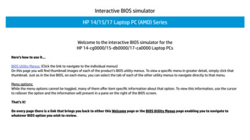
MSP430's USB SupportWe’ll address many of the data/system oriented features throughout the rest of the presentation.You might note here, though, the hardware specific features. For example, “including the PHY”(physical interface) means there’s one less thing for you to put on your board. Also, the USB porthas its own dedicated block of SRAM (though the system can use it when the USB port isdisabled).USB Block DiagramaSP430 USB Peripheral Supports USB 2.0 standardDevice only(Host not supported– try Tiva-C from TI) Full speed USB device (12abps) Includes 16 Endpoints (8-in/8-out)Certified USB module Integrated transceiver (PHY)Integrated 3.3V LDO for directoperation from USB busProgrammable PLL(generates 48aHz USB clock)Integrated D pull-up resistor (PUR)Also, notice the LDO voltage regulators. These let the port (and even the MSP430 device itself)operate from the 5V supply coming from an attached USB cable. Finally, the built-in PLLhandles the required USB clock requirements, utilizing one of the MSP430 external clock inputs.10 - 10MSP430 Design Workshop - USB Devices
MSP430's USB SupportWe bragged about the MSP430 development support. Here’s a peek at it. Looking at the itemspointed out by the red arrows: We begin with the excellent USB Programmers Guide The Descriptor Tool is truly unique. It makes easy work of the tedious (and error prone)job of creating USB interface descriptors. The USB HID Demo is a Host-side tool that lets you interact with custom devicesimplementing the Human Interface Device class. It’s like a serial terminal program for HIDdevices. Finally, the rich set of examples provided by TI not only provides a way to “play” withUSB, they also make excellent starting points for your own applications.USB Developers PackageMSP430 Design Workshop - USB Devices10 - 11
MSP430's USB SupportSidebar – MSP430 USB API FeaturesMSP430 USB API Features1. A finished API– Not just example code– Increases chance of USB success, because the user doesn’t need to modifythe USB plumbing; speeds development– An API approach makes USB more accessible to USB non-experts2. Small memory footprint– Single-interface CDC or HID: 5K flash / 400 bytes RAM– MSC (not including file system / storage volume): 8K flash / 1.4K RAM3. Can use either DMA or CPU to move data– Simply turn the DMA feature ‘on’ and select the channel4. Limited resource usage– Only uses the USB module, some memory, & a DMA ch; no other resources5. RTOS-friendly– TI will soon provides using it with TI-RTOSMSP430 USB API Features, cont.6. Responsiveness– No risky blocking calls stuck waiting for the host– Data can be transferred “in the background”, for increased systemresponsiveness and efficiency, even with a busy host/bus7. Easy data interface (CDC and HID-Datapipe)– The function calls are similar to interfacing with a simple COM port– You can send/receive data of any size, with a single call -- no packetizationrequired– Deep USB knowledge not required8. Flexibility (MSC)– Compatible with any file system software. (We provide the open-source“FatFs” as an example.)– Easy multiple-LUN support; just select the number of LUNs– No RTOS required – but can be ported to one10 - 12MSP430 Design Workshop - USB Devices
MSP430's USB SupportUSB FeesAs we described earlier, your USB product needs a Vendor and Product ID (VID & PID) in orderto meet the requirements of the standard. The USB Implementers Forum (USB-IF) charges a feeto license a Vendor ID.As an alternative to purchasing your own VID, silicon vendors such as Texas Instruments, willprovide you the ability to use their VID when using the MSP430 USB-based devices. Please referto TI’s website for more information on obtaining a VID/PID.MSP430 Design Workshop - USB Devices10 - 13
MSP430's USB SupportAdditional USB ResourcesAlong with TI’s MSP430 USB page, we’ve provided some USB references that we found useful.Suggested Reading “Starting a USB Design Using aSt430 aCUs” App Note by Keith Quiring(Sept 2013) (Search ti.com for SLAA457.pdf) “trogrammers Guide aSt430 USB AtI” by Texas Instruments (Aug 2013)Found in the aSt430 USB Developers tackage “USB Complete: The Developer's Guide” by Jan Axelson (ISBN lopers-Guide-Guides/dp/193144808610 - 14MSP430 Design Workshop - USB Devices
How USB WorksHow USB WorksAs we stated at the beginning of the chapter, USB is a serial, Master/Slave communicationprotocol. That is, the Host acts as the Master; communication to and from the Host is directed bythe Host. The Device only responds to requests from the Host.The USB standard allows many Devices to be connected to a single Host. The Host assigns anaddress to each Device as it is connected (i.e. enumerated) to the Host. This is really a minordetail, though, since – as a Device – we don’t need or use this information.Logical Connection Between Host & DeviceMaster Host Communication takes placebetween the host and device Host controls ALL communication Device is addressable(assigned by host)SlaveDeviceMSP430 Design Workshop - USB Devices10 - 15
How USB WorksPipes and EndpointsTo be more specific, a Host communicates with a Device through a Pipe; that is the name givento this communication pathway. The Pipe makes a connection to a Device Endpoint; which isessentially just a buffer in the Device. (As we’ll see in a minute, the MSP430 has dedicatedEndpoints in its USB port hardware.)Communication PipesHostPipe Host/Device communication occursthru a Pipe The host sets up pipe connectionsto one or more device “endpoints” An endpoint is essentially a bufferin the deviceEndpointDevice10 - 16MSP430 Design Workshop - USB Devices
How USB WorksPipes specify unidirectional data movement. If you want to move data in both directions, twoPipes must be created – which requires 2 Endpoints. Also, seeing as Pipes (and USB, in general)are Host centric, the directions In and Out are from the Host’s perspective.Communication PipesHostPipesOut In Host/Device communication occursthru a Pipe The host sets up pipe connectionsto one or more device “endpoints” An endpoint is essentially a bufferin the device Pipes/Endpoints are unidirectional In/Out is from the Host perspectiveEndpointsDeviceMSP430 Design Workshop - USB Devices10 - 17
How USB WorksWhile the USB standard only requires a Device to have one Input and one output Endpoint, theMSP430 USB port provides 16 Endpoints: 8 Input and 8 Output. Additionally, the MSP430Endpoints each contain a 64-byte buffer – the largest specified in the USB specification. All-in-all,this hardware provides the MSP430 with a lot of flexibility in the types of communications itsupports.As shown below, the set of Input and Output Endpoints are numbered 0 – 7.MSP430 Supports 8 Ins/OutsHostPipesOut InEndpoints00Device11 77 Host/Device communication occursthru a Pipe The host sets up pipe connectionsto one or more device “endpoints” An endpoint is essentially a bufferin the device Pipes/Endpoints are unidirectional In/Out is from the Host perspective Endpoints are enumerated (from 0) Endpoint 0 is special case – all USBdevices must have EP0, which isused for setup and controlMSP430 Endpoints: 16 endpoints (8 in, 8 out)Each has 64 byte bufferWhat goes across pipes?We often see the Endpoints referred to as EP0, EP1, EP7.The In/Out Endpoints do not have to be used in bidirectional pairs – sometimes you may find thatyour Device needs 2 Inputs and 1 Output.By the way, do you remember when we said that the USB spec requires a Device to have at least1 Endpoint?That happens to be Endpoint 0 (EP0). EP0 is a special case; the Host uses EP0 (both directions)to setup and control USB operations. Without the Host being able to rely on a known Endpoint 0always being available, it wouldn’t know how to start talking to new Devices as they’re physicallyconnected.So, we’ve established the concept of a communication Pipe what gets transferred across it?10 - 18MSP430 Design Workshop - USB Devices
How USB WorksUSB Transfer TypesAlong with specifying an Endpoint and direction, a Pipe also specifies the “Type” ofcommunication transfer. The USB specification supports four Transfer Types, as defined in thisdiagram.USB TransfersHost Pipe’s define a Transfer Type aswell as the endpoint and directionUSB supports 4 Transfer Types: Pipes Out In Endpoints001Device1 77 ControlInterruptSetup/Command/StatusSmall size, PeriodicGuaranteed latencyGuaranteed bandwidthBulkLarge size allowedNo time guaranteesIsochronous Guar. time, PeriodicNo error handlingNot supported on ‘430Contrary to the name, ‘interrupt’transfers are not initiated by deviceHow should we Frame this discussion?If all we cared about was passing data across the Pipe, we wouldn’t need to further define theTransfer Type of a Pipe. The fact is, sometimes we care about “when” data will arrive, just asmuch as the data itself.Each of the Transfer Types, listed above, briefly describe their temporal nature. Notice how“Interrupt” types provide a guaranteed latency and bandwidth, although the tradeoff is a smallerdata payload. Conversely, “Bulk” transfers allow large sizes, but give up the time-orientedguarantees.Hint:“Interrupt” transfer types do not have anything to do with microprocessor “interrupts”. It isjust the word used in the USB specification to describe these types of transfers.Similarly, “Interrupt” transfer types are initiated by the Host, just as all USB transfers areinitiated and controlled by the Host. (We’ll see more about this on the next page.)Note:The MSP430 USB stack (i.e. USB library) only supports Control, Interrupt, and Bulktransfer types. Currently, the MSP430 does not support Isochronous types, which aremore typically used in audio or video types of applications.MSP430 Design Workshop - USB Devices10 - 19
How USB WorksThe USB FrameIf we’re talking about time-oriented concepts, such as latency and bandwidth, how are thesedefined?USB describes communications occurring within a 1 ms Frame. Each Frame begins with a Startof-Frame (SOF). After that comes ‘interrupt’ transfer types, then ‘control’ types, and finally ‘bulk’transfer types.In this way, interrupt transfers are guaranteed to occur. Conversely, if you have so many interrupttransfers that the frame is near fully utilized, then bulk transfers might occur very slowly. Thenagain, if you don’t have many interrupt or control transfers, bulk transfers will get most of theframe and complete more quickly.Providing further flexibility, periodic transfer types (e.g. interrupt transfers) can be configured tooccur in every frame – or as infrequently as once every 255 frames. This lets you specify theamount bandwidth and latency needed for a given periodic transfer – as well as potentially freeup bandwidth for bulk transfer types.10 - 20MSP430 Design Workshop - USB Devices
How USB WorksSidebar – PacketsRealistically, large transfers must be broken down into smaller chunks. USB defines thesesmaller chunks as ‘packets’.We’ve chosen not to dig into the details of packets – or a number of other details likehandshaking, error detection, and so on. This decision was based on two factors: one, there justisn’t enough time to go through every detail of the USB specification in this chapter; and two, theUSB peripheral’s hardware – and the TI USB stack – manage these details for us. In other words,we don’t have to know them in order to get our USB application built and working.MSP430 Design Workshop - USB Devices10 - 21
Descriptions and ClassesDescriptions and ClassesAs we say on the following slide, “What do you want to Transmit?”Are you looking to send data across the USB bus similar to a standard serial port? Maybe you’rebuilding a human interface device and want to send mouse or keyboard data.What Do You Want to Transmit? USB devices describe one (or more) Interfaces to transmit informationTypical interface examples: Creating a Virtual COM port requires 2-in and 1-out endpoints Human interface devices (mice/keyboards) require 1-in/1-out Memory devices also require 1-in/1-outDevice DescriptorsSetup &/ontrolVirtual/ha tortEP0 EP0EP1 EP1 EP2aouseYeyboard EP6 EP6EP7 EP7Configuration Interface(s) Endpoint(s)Device (example shown here is ‘composite’ device with multiple I/F’s)10 - 22MSP430 Design Workshop - USB Devices
Descriptions and ClassesSummary – USB Interface DescriptionUSB devices describe one (or more) Interfaces to transmit informationTypical interface examples: Creating a Virtual COM port requires 2-in and 1-out endpoints Human interface devices (mice/keyboards) require 1-in/1-out Memory devices also require 1-in/1-out USB devices must describe their themselves using device descriptors Host must match descriptors (at run time) with host-side device drivers (INF) MSP430 supports a single configuration withDevice Descriptorsone or more interfaces Configuration Interface(s)VirtualSetup & Endpoint(s)aouseKeyboard/ha tort/ontrol EP0 EP0EP1 EP1 EP2 EP6 EP6EP7 EP7Device (example shown here is ‘composite’ device with multiple I/F’s)MSP430 Design Workshop - USB DevicesHow can we simplifyconfiguration?10 - 23
Descriptions and ClassesUSB ClassesUSB defines a number of device classes: Human InPerface Device (HID)MSP430 SupporPs 4 classes HID, CDC, MSC (and PHDC) CommunicaPions Device (CDC) HosP OCS can easily maPcO iPs Memory SPorage Class (MSC)drivers Po known device classesSimplifies specifying inPerfaces(e.g. creaPing descripPors) DescripPors Pake form of: Device: daPa-sPrucPures“IID” HosP:.INF file “CDC”“IID”Setup &ControlVirtualCOa PortaouseKeyboardEP0 EP0EP1 EP1 EP2 EP6 EP6EP7 EP7Device10 - 24Is POere an easy way PocreaPe USB DescripPors?MSP430 Design Workshop - USB Devices
Descriptions and ClassesDescriptor Tool: API Integration The Tool is tightly integrated with the API Generates three source files that configure the rest of the stack Also generates the INF file (for CDC on Windows)descriptors.hConfigurationconstantsAPI Stackdescriptors.cDescriptorStructuresINF Fileusbisr.cCommunications Data Class (CDC) Implements a virtual COa port on tCSimple serial terminal on Host side(e.g. HyperTerm, tutty, Tera Term)The AtI presents a generic datainterface to the applicationSend/receive data of any size, with asingle function callUses simple calls like: Can be performed “in the background” MSP430 Design Workshop - USB DevicesUSB connect();USB sendData(buffer, size, intfNum);USB receiveData(buffer, size, intfNum);Increases program responsivenessImproves efficiency10 - 25
Descriptions and ClassesHuman Interface Device (HID) IID classes transfers data in ‘report’structures aSt430 supports any report type,but are 3 are built-in: (traditional)(traditional)(generic)‘Datapipe’ presents a generic datainterface to the application Datapipe mode allows the benefits ofIID without some of its downsides Silent loading on the host Avoids USB’s complex IID reportstructures Enables a unique value tradeoffKeyboardaouseDatapipe aakes it easy to use IID for a CDClike interfaceTI provides a IID host demo tool(which acts like host-side serialterminal for datapipe xfers)Application code interchangeablewith CDC code, for easy migrationaSt430 also provides AtIs for hostside IID development: WindowsaacMemory Storage Class (MSC) Allows easy creation of a USBstorage deviceNo RTOS required USB Developers tackageincludes a port of the opensource CAT file system (CatCS) But can easily be ported to oneTI-RTOS (coming soon for aSt430)will provide a port with examplesCatCS is provided as an exampleUSB stack was designed to becompatible with any file systemCive demo apps providedaSC will be covered in moredetail in an new chapter underdevelopment10 - 26MSP430 Design Workshop - USB Devices
Descriptions and ClassesComparison/SummaryCDCHIDof ClassesMSCHostInterface/Oa tortUser InterventionHost Ioading (user loads .inf file)IID deviceStorage VolumeSilentSilentBandwidtO“Iundreds of KB/sec”62KB/sec“Iundreds of KB/sec”Code Size5K5K(12-15K w/CS & vol)Endpoints2 in1 outTransferTypeAdvantagesBulk Camiliar to user Bulk transport /ommon host appsMSP430 Design Workshop - USB Devices1 in1 outInterrupt Silent loading Interrupt xfers aouse/Keybd9K1 in1 outBulk (BOT) Camiliar to user Allows storage ofdata using filesys10 - 27
Quick Overview of MSP430’s USB StackQuick Overview of MSP430’s USB Stack10 - 28MSP430 Design Workshop - USB Devices
Quick Overview of MSP430’s USB StackMSP430 Design Workshop - USB Devices10 - 29
Notes:
ABC’s of USBABC’s of USBA. Plan Your SystemPlan Your System1.What are your requirements? How much data needs to transfer and how fast?Is guaranteed bandwidth & timing important?Are you connecting to Window, aac, Linux (or all)What power will be needed?2.From the requirements, decide which class(or classes) will be needed3.Import EmptyUsbtroject (Optional)4.Run Descriptor Tool trovides help & feedback in creating device descriptionGenerates device descriptor files & INF filesIf you followed step 3, it automatically drops generatedfiles into the projectMSP430 Design Workshop - USB Devices10 - 31
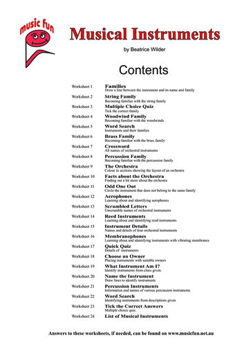
ABC’s of USBB. Connect & EnumerateSix States of Connection1. USB is disconnected ST PHYSDISCONNECTED User plugs in device& VBUS (power) appears2.USB Connected, not enumerated handleVbusOnEvent()ST PHYS CONNECTEDNOENUM App calls USB Setup(), whichpulls tUR up3. Enumeration in trogressRST PHYSCONNECTEDNOENUM SUSPST ENUM INPROGRESSn ]:Enumeration [ iO-noo-muh-re -sOuhx ST ENUMACTIVEthe process in which the hostobtains the descriptors andloads the correct driverST ENUM SUSPENDEDSix States of Connection1. USB is disconnected ST PHYSDHSCONNECTED User plugs in device& VBUS (power) appears2.USB Connected, not enumerated handleVbusOnEvent()ST PHYS CONNECTEDNOENUM App calls USB Setup(), whichpulls tUR up3. Enumeration in trogressRST ENUM HNPROGRESSxST ENUMACTHVE Enumeration succeeds4. Device is enumerated, bus active handleEnumCompleteEvent()ST PHYSCONNECTEDNOENUM SUSP Host Suspends device/bus5. Device is enum, but suspended handleSuspendEvent()ST ENUM SUSPENDEDCan Re affect connection sta
MSP430's USB Support MSP430's USB Support As we stated on the first page, the MSP430 proves to be an excellent solution for building USB Devices. Many devices in the F5xx and F6xx MSP families contain the USB peripheral. Coupling this proven USB hardware port with the low-power nature of the MSP430 makes possible some interesting USB applications.