Transcription
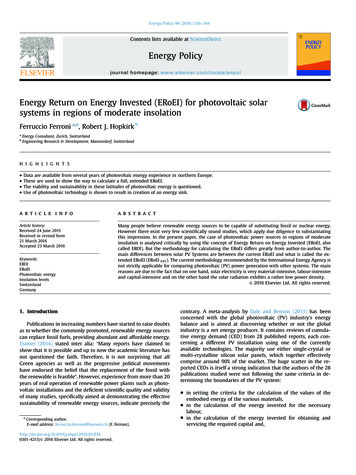
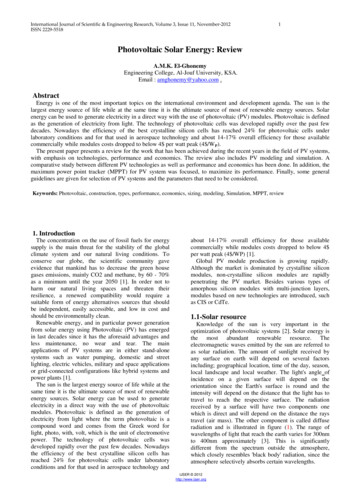
International Journal of Scientific & Engineering Research, Volume 3, Issue 11, November-2012ISSN 2229-55181Photovoltaic Solar Energy: ReviewA.M.K. El-GhonemyEngineering College, Al-Jouf University, KSA.Email : amghonemy@yahoo.com .AbstractEnergy is one of the most important topics on the international environment and development agenda. The sun is thelargest energy source of life while at the same time it is the ultimate source of most of renewable energy sources. Solarenergy can be used to generate electricity in a direct way with the use of photovoltaic (PV) modules. Photovoltaic is definedas the generation of electricity from light. The technology of photovoltaic cells was developed rapidly over the past fewdecades. Nowadays the efficiency of the best crystalline silicon cells has reached 24% for photovoltaic cells underlaboratory conditions and for that used in aerospace technology and about 14-17% overall efficiency for those availablecommercially while modules costs dropped to below 4 per watt peak (4 /W P).The present paper presents a review for the work that has been achieved during the recent years in the field of PV systems,with emphasis on technologies, performance and economics. The review also includes PV modeling and simulation. Acomparative study between different PV technologies as well as performance and economics has been done. In addition, themaximum power point tracker (MPPT) for PV system was focused, to maximize its performance. Finally, some generalguidelines are given for selection of PV systems and the parameters that need to be considered.Keywords: Photovoltaic, construction, types, performance, economics, sizing, modeling, Simulation, MPPT, review1. IntroductionThe concentration on the use of fossil fuels for energysupply is the main threat for the stability of the globalclimate system and our natural living conditions. Toconserve our globe, the scientific community gaveevidence that mankind has to decrease the green housegases emissions, mainly CO2 and methane, by 60 - 70%as a minimum until the year 2050 [1]. In order not toharm our natural living spaces and threaten theirresilience, a renewed compatibility would require asuitable form of energy alternatives sources that shouldbe independent, easily accessible, and low in cost andshould be environmentally clean.Renewable energy, and in particular power generationfrom solar energy using Photovoltaic (PV) has emergedin last decades since it has the aforesaid advantages andless maintenance, no wear and tear. The mainapplications of PV systems are in either stand-alonesystems such as water pumping, domestic and streetlighting, electric vehicles, military and space applicationsor grid-connected configurations like hybrid systems andpower plants [1].The sun is the largest energy source of life while at thesame time it is the ultimate source of most of renewableenergy sources. Solar energy can be used to generateelectricity in a direct way with the use of photovoltaicmodules. Photovoltaic is defined as the generation ofelectricity from light where the term photovoltaic is acompound word and comes from the Greek word forlight, photo, with, volt, which is the unit of electromotivepower. The technology of photovoltaic cells wasdeveloped rapidly over the past few decades. Nowadaysthe efficiency of the best crystalline silicon cells hasreached 24% for photovoltaic cells under laboratoryconditions and for that used in aerospace technology andabout 14-17% overall efficiency for those availablecommercially while modules costs dropped to below 4 per watt peak (4 /WP) [1].Global PV module production is growing rapidly.Although the market is dominated by crystalline siliconmodules, non-crystalline silicon modules are rapidlypenetrating the PV market. Besides various types ofamorphous silicon modules with multi-junction layers,modules based on new technologies are introduced, suchas CIS or CdTe.1.1-Solar resourceKnowledge of the sun is very important in theoptimization of photovoltaic systems [2]. Solar energy isthe most abundant renewable resource. Theelectromagnetic waves emitted by the sun are referred toas solar radiation. The amount of sunlight received byany surface on earth will depend on several factorsincluding; geographical location, time of the day, season,local landscape and local weather. The light's angle ofincidence on a given surface will depend on theorientation since the Earth's surface is round and theintensity will depend on the distance that the light has totravel to reach the respective surface. The radiationreceived by a surface will have two components onewhich is direct and will depend on the distance the raystravel (air mass). The other component is called diffuseradiation and is illustrated in figure (1). The range ofwavelengths of light that reach the earth varies for 300nmto 400nm approximately [3]. This is significantlydifferent from the spectrum outside the atmosphere,which closely resembles 'black body' radiation, since theatmosphere selectively absorbs certain wavelengths.IJSER 2012http://www.ijser.org
International Journal of Scientific & Engineering Research, Volume 3, Issue 11, November-2012ISSN 2229-5518Direct BeamCloud anddust etc.Diffuse sunlightFigure (1): Types of radiation from the sun [3]1.2-PV HistoryThe history of PV dates back to 1839 when aFrench physicist, Edmund Becquerel, discoveredthe first photovoltaic effect when he illuminated ametal electrode in an electrolytic solution [16].Thirty-seven years later British physicist, WilliamAdams, with his student, Richard Day, discovered aphotovoltaic material, selenium, and made solidcells with 1 2% efficiency which were soon widelyadopted in the exposure meters of camera [16].In 1954 the first generation of semiconductorsilicon-based PV cells was born, with efficiency of6% [3], and adopted in space applications. Today,the production of PV cells is following anexponential growth curve since technologicaladvancement of late ‘80s that has started to rapidlyimprove efficiency and reduce cost.1.3-Spectrum of the sunTwo different spectral distributions have beendefined for the sun. The AM0 spectrum relates toradiation in outer space and the AM 1.5 G spectrumis at sea level at certain standard conditions. Thephotovoltaic (PV) industry and the American Societyfor Testing and Materials (ASTM), Americangovernment research and development laboratorieshave developed and defined two standard terrestrialsolar spectral irradiance distributions: a standarddirect normal and a standard total spectralirradiance. An instrument called the pyranometer isused to measure global radiation. This instrument isdesigned to respond to all wavelengths andtherefore gives an accurate value of the total powerin any incident spectrum.1.4-Standard test conditions (STC)21. The reference vertical irradiance Eo with a typicalvalue of 1000W/m22. Reference cell temperature for performance rating, Towith a typical value of 25 0C and a tolerance of 2 0C;3. A specified light spectral distribution with an air mass,AM 1.5. Air mass figures provide a relative measureof the path the sun must travel through the atmosphere.In addition to supplying performance parameters at theStandard Test Conditions manufacturers also provideperformance data under the Nominal Operating CellTemperature (NOCT) [4]. This is defined as thetemperature reached by the open circuited cells in amodule under the following conditions:-Irradiance on cell surface is 800 W/m2- The ambient temperature is 200C (293 K)- Wind speed is 1m/s and the mounting is open back sideTo account for other ambient conditions theapproximate expression below may be used:NOCT 20Tcell Tamb G0.8Where Tcell is cell temperature (0C), Tamb is the ambienttemperature, (NOCT) is the Nominal Operating CellTemperature and G is the solar insolation (kW/m2).1.5-How do solar panels work?Solar panels are made up of photovoltaic cells thatconvert sunlight directly into electricity by using asemiconductor, usually made of silicon. The termphotovoltaic comes from the Greek meaning “light”(photo) and “electrical” (voltaic). When the sunlight hitsthe photovoltaic cells, part of the energy is absorbed intothe semiconductor. When that happens the energyloosens the electrons which allow them to flow freely.The flow of these electrons is a current and when you putmetal on the top and bottom of the photovoltaic cells, wecan draw that current to use it externally.1.6-Advantages of PV powered systemsPV systems are highly reliable and are often chosenbecause they offer the lowest life-cycle cost, especiallyfor applications requiring less than 10KW, where gridelectricity is not available and where internal-combustionengines are expensive to operate [1]. If the water sourceis 1/3 mile (app. 0.53Km) or more from the power line,PV is a favorable economic choice [1]. Table (1) showsthe comparisons of different stand-alone type waterpumping System-Lowmaintenance-Unattendedoperation-Reliable longlife-No fuel andno fumes-Easy to install-Low recurrentcosts-System is modularand-closely matched toneed-Relatively highinitial cost-Low outputin cloudyweatherUniform conditions are usually specified so that aperformance comparison can be made between differentPV units (cell, modules). The parameters obtained fromthe testing are usually provided on the manufacturer'sdatasheet. Measurements are performed under thesestandard test conditions and the electrical characteristicsobtained characterize the module accurately under theseconditions. The conditions are specified as follows:IJSER 2012http://www.ijser.org
International Journal of Scientific & Engineering Research, Volume 3, Issue 11, November-2012ISSN 2229-5518Diesel(or Gas)PoweredSystemWindmill-Moderate capitalcosts-Easy to install-Can be portable-Extensive experienceavailable-Needs maintenanceandreplacement-Site visits necessary-Noise, fume, dirtproblems-Fuel often expensiveandsupply intermittent-High maintenance-Seasonaldisadvantages-Difficult findparts thuscostly repair-Installationis laborintensive and needsspecialtools-No fuel and nofumes-Potentiallylong-lasting-Works well inwindy sitesTable 1-1: PV powered, Diesel powered, vs. e (2): The Annual horizontal solar energy available insome countries [1].The main aim of this paper is to provide acomprehensive review about photovoltaic systems. Thestudy was extended to include Photovoltaic construction,2.1-Solar radiation in KSA:types, performance, economics, sizing, modeling, andSimulation. Also, the principle and operation of the PVcell and the fundamental characteristics of PV cell arediscussed. Finally, a special attention was given to focuson the following points:-Potential of solar energy-PV materials-Future and Market growth of Solar Panels-Photovoltaic performance-Photovaltaic systems-PV hierarchy-Photovaltaic technology-Photovoltaic Electrical System-Factors Affecting PV Output-Solar Cell Limitation-Components sizing of PV system-Economic evaluation-Modeling and simulation-Maximum Power Point Tracker (Load type effect,Algorithms, control and Limitations)2-Potential of solar energyEnergy experts expect that in the year 2050, over 50%and 80% of all electricity could be generated byrenewable energy . Among the potential sources ofrenewable energy, solar thermal power plants areconsidered to be one of the most economic.The understanding of each technology and itsassociated challenges will provide a suitable basis torecognize advantages and drawbacks. The Annualhorizontal solar energy available (kWh/m2) and relativepeak value (W/m2) in some countries is given in table (2)[1].CountryAnnualSolar t of solar radiation resources in differentcities of KSA is given in table (3). The daily and annualdistribution pattern of solar energy at given locations areessential not only for assessing the economic feasibilityof solar energy utilization, but also for the thermal designand environmental control of buildings and greenhouses.The solar radiation data for the Northern of KSA(SKAKA region) were obtained from the NASA surfacemeteorology and solar energy Web site [1]. The Averagesolar data over a 1-year period was obtained and plottedin figure (2). From these results, the average solar2radiation is 5.77, 7.22 kWh/m /day for horizontal andtilted plane respectively. Moreover, the annual averagedaylight hours are 12 hrs. A brief list of solar energyprojects that has been applied in KSA is given udemGlobalRadiationWh/ aNajranQurayyatRiyadhSakakaTabukTaifYabrin180 13\250 30\420 29\490 34\220016058245671SunshineDurationhours8.78.7260 33\200 01\240 25\270 28\240 31\50\ 00\420 36\460 34\410 38\390 1170 33\310 20\440 14\370 21\12502693655629.19.0240 34\290 58\280 23\210 14\230 19\460 43\400 12\360 35\400 21\480 99.1Table (3): solar radiation resources in different cities ofKSA[10,11]IJSER 2012http://www.ijser.org
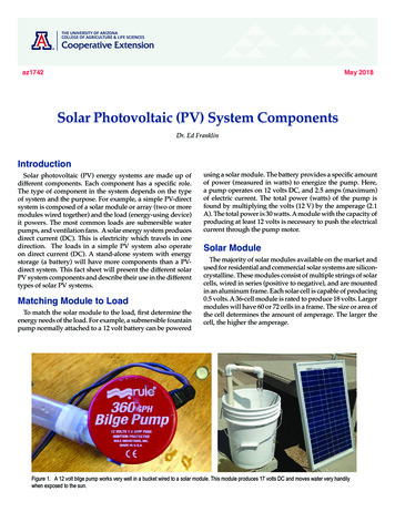
International Journal of Scientific & Engineering Research, Volume 3, Issue 11, November-2012ISSN 2229-5518Average solar data for SKAKA areas35302520H horiH tSelyuguAneJuMayJuprilAbMarchFeJanPSSHFigure (2): Average solar data over a 1-year periodFor Northern of KSA (SKAKA area) [10,11].3-PV materialsPV cells are made of semiconductor materials withcrystalline and thin films being the dominant materials.The majority of PV-cells are silicon-based but in the nearfuture other thin film materials are likely going to surpasssilicon PV cells in terms of cost and performance [2]. PVmaterials may fall into one or more of the followingclasses: crystalline, thin film, amorphous, multi-junction,organic or photochemical.4such as glass, metal or plastic. Epitaxial processes (suchas vapor deposition, sputter processes and electrolyticbaths) are used to achieve this. Because thin-filmmaterials have high absorptivity, the deposited layer ofPV material is extremely thin. This results in thereduction of the dominating material cost although thinfilm PV cells suffer from poor cell conversion efficiency.There are several types of thin-film materials [5].-Amorphous siliconThis material has a significant advantage of higherlight absorptivity. About 40 times that of crystallinesilicon. It can be deposited on a low cost substrate andthe manufacturing process requires low temperature andtherefore less energy. It has lower material andmanufacturing costs. Amorphous hydrogenated silicon(a-Si:H) has been widely used by the Japanese to powersmall consumer goods such as watches and calculators[5]. This material is a non-crystalline for silicon and doesnot form a regular crystal structure, but an irregularnetwork. The material is highly defective even withhydrogenation so the minority carrier lifetimes are verylow resulting in low conversion efficiency. A majordrawback of this material is that it degrades under sunexposure, a mechanism called the Staebler-Wroskieffeect.3-a-Crystalline materials-Single-crystal siliconMono-crystalline silicon cells have in the pastdominated the PV market but have now been overtakenby poly-crystalline silicon. The popularity of monocrystalline silicon was due to the good stability anddesirable electronic, physical and chemical properties ofsilicon. Moreover, silicon was already successful inmicroelectronics and the enormous industry thus createdwould benefit the smaller PV industry with regards toeconomy of scale [2].-Poly-crystalline siliconThis is the currently most dominant material and hassurpassed the mono-crystalline because it is cheaper. Thecost of silicon is a significant portion of the cost of thesolar cell. The manufacturing processes of polycrystalline silicon reduce the cost of silicon by avoidingpulling in the manufacturing process and it results in ablock with a large crystal grain structure. This results incheaper cells with a somewhat lower efficiency. Theassembly of multi-crystal wafers is easier and thereforeoffsets the low efficiency disadvantage.-Cadmium Telluride (CdTe)This is one of the most promising thin lm solar cells.The material is a poly-crystalline semiconductorcompound made of cadmium and tellurium. CdTe has thelowest production cost among the current thin-filmtechnologies. Low-cost soda-lime glass is used as thesubstrate. The manufacturing processes have greatlyimproved over the past few years. The CdS film is growneither by chemical bath deposition (CBD), close spacesublimation (CSS), chemical vapor deposition (CVD),sputtering, or vapor transport deposition (VTD). Thismaterial has a very high absorption coefficient.3.b-Thin-film materials-Copper Indium Diselenide (CIGS)CIGS is a polycrystalline semiconductor compound ofcopper, indium and selenium, and has been a majorresearch area in the thin film industry. It is anotherpromising material for thin-film solar cells. It can achievehigh energy conversion efficiency and does not sufferfrom outdoor degradation problem and has demonstratedthat thin film PV cells are a viable and competitivechoice for the solar industry in the future.This material also has a high absorption coefficientwith only 0.5 micrometers needed to absorb 90% of thesolar spectrum. However it is a very complex materialmaking it difficult to manufacture. Moreover itsmanufacturing process involves hydrogen selenide, anextremely toxic gas raising safety concerns.Since the 1990s development of thin-film, processesfor manufacturing solar cells have increased. These PVdevices are made using very thin semiconductor filmsdeposited on some type of low-cost structural substrate4-Future and Market growth of SolarPanels-Gallium ArsenideThis material is a compound semiconductor made ofgallium and arsenic. It has a crystalline structure and hasa high level of light absorptivity. GaAs has higherefficiency than silicon but its main drawback is its cost. Itis used in space applications and in concentrator systems.IJSER 2012http://www.ijser.org
International Journal of Scientific & Engineering Research, Volume 3, Issue 11, November-2012ISSN 2229-55185grew by 380% between 1998 and 2003, and the annualgrowth is also increasing, with module shipmentsincreasing by approximately 33 % from 2002 to2003[6].The crystalline silicon technologies have morethan 90% of the market share of module shipments butfigure(3) shows increased production of othertechnologies such as a-Si and CdTe. Many factorscontribute to interest in thin film technologies. Thesefactors include: improved efficiency and efficiencystability, lower cost of manufacture and the potential tomanufacture the thin film devices in large area sheets andwith a flexibility that is not provided by conventionalcells made on crystalline wafer substrates4.1-History of PV marketSolar energy production has been doubling every twoyears, increasing by an average of 48 percent each yearsince 2002, making it the world’s fastest-growing energytechnology. One day of sunshine produces enough energyto power the planet for a year and solar panel technologyis improving drastically to harness this powerful sourceof clean energy. The cost of electricity from your utilitycompany is always going to go up, and as the demand forsolar panels grow, the less expensive they will become.The worldwide increase in PV module shipments andthe breakdown into technology types can be seen infigure(3).The large increase in production of the newerthin film modules is clearly apparent . the PV industryFigure (3): History of total world module shipments.[6]Figure (4): World and European PV markets in 2009 in MW [7].IJSER 2012http://www.ijser.org
International Journal of Scientific & Engineering Research, Volume 3, Issue 11, November-2012ISSN 2229-5518MaterialSi (crystalline)Si(large crystalline)Si (multicrystalline)Si (thin-film polycrystalline)CIGSSCdTe (thin film)a-Si/A-SiGe/a-SiGe (tandem)Efficiency22:7 0.620:1 0.615:3 0.48:2 0.213:4 0.710:7 0.510:4 0.3282.163.2053.2856Fill Factor (FF)80.378.778.668.068.962.366.0Table (4): Confirmed terrestrial module efficiencies measured under the global AM1.5 spectrum [5]The future of the Photovoltaic industry is promising asthe efficiency of the cell and sub-modules continues toincrease. The table (4) shows the most recent confirmedefficiency of modules of various photovoltaic materials[7]. As technology and manufacturing processes continueto improve higher efficiencies are expected in the nearfuture.Bulk crystalline Si devices are likely going to remaindominant for the next decade. Thin- lm technologies arematuring fast and may soon challenge the market share ofcrystalline Silicon devices. The dominant futuretechnology will be determined largely by materialavailability and costs.The increase of conventional energy prices hasincreased the investment attention for renewable energiesand in particular photovoltaics significantly. Since 2006the investments and growth in thin film photovoltaicshave surpassed the already high growth rates of the wholephotovoltaics industry but have recently slowed due totechnology and financial reasons.Thin film solar cells still offer the possibility ofreducing the manufacturing costs considerably; however,considering the increasing maturity of wafer-basedproduction technologies, observed learning curves, andrecent cost reductions, newcomers have to enter the gameat already very competitive levels. In addition, the entryticket, that is, factory size for thin film manufacturers intothe market, has increased from a 20MW factory in 2006to a minimum of 100MW in 2011and is still growingwith the increasing market volume[7].Thin film technologies still need a lot of research overa wide range of issues, ranging from improvement of theunderstanding of basic material properties to advancedproduction technologies and the possible marketperspectives. To tackle these problems, a long-termvision for photovoltaics and long-term research areneeded.However, there is no “winning technology” and aviable variety of technology options have to be ensured.To focus on any single technology option now could be aroad block in the future. Public research fundingstructures should take into account that differenttechnologies are at different development stages and needdifferent kind of support measures.if and how they can be utilised for PV in the future. Thisis especially important for thin film solar cell materials,that have only a limited backing by other industries, suchas that provided by the microelectronic industry, in thedevelopment of production technologies for silicon solarcells. In addition, there are a number of research issuescommon to all thin film technologies which have to besolved. No single solar cell technology can neither satisfythe world-wide demand nor all the different wishesconsumers have for the appearance or performance of PVsystems.4.2-PV Market size by country in 2009[2]The European Union represented 5.6 GW or 78% ofthe World PV market in 2009(figure (4)). And in Europeitself, the German market clearly dominates with 68 % ofthe EU market. The emergence of Italy as a major marketfor PV, combined with the ramp-up of France and theimpressive growth of the Czech Republic and Belgium,compensated the slowdown of the Spanish market. Onemajor change in 2009 is the emergence of new marketsoutside Europe, with Canada and Australia starting todevelop while Japan and the USA show both a significantpotential in becoming new GW markets in the comingyears.4.3- PV production size by country andtechnology in 2009, figure (5)[6,7].In 2009, the regional distribution of productioncapacities differed significantly depending on the type ofproduct and its position in the value chain. C-Si cells andmodules production capacity seemed to be dominated byChinese and Taiwanese manufacturers (above 50% inboth cases). European production capacity counted foralmost 20% for c-Si cells and almost 30% for c-Simodules. In Japan, both figures are below 10% whereasthe USA production counts for only 5%. The picture isdifferent when considering solar grade silicon productioncapacity with up to 40% in the USA, followed by Europeand China, both having similar levels of productioncapacity (almost 20%) and Japan and the rest of Asia(both slightly above 10%). With respect to Thin Filmproduction capacities, Europe leads with around 30%,whereas China, the USA, Japan and the rest of Asia(mainly Malaysia) each count for about 10 to 20% ofThin Film production capacities.In order to realise high production volumes for PV wemust now look towards already available highthroughput, high-yield production technologies analysingIJSER 2012http://www.ijser.org
International Journal of Scientific & Engineering Research, Volume 3, Issue 11, November-2012ISSN 2229-55187that during the silicon shortage over the last few years,many companies invested in Thin Film productionfacilities. Manufacturers are still ramping up, optimisingthe production and/or struggling to get to the optimal coststructure to be competitive. This is especially challengingwith much lower prices of polysilicon which result inlower prices for c-Si modules.Figure (5) - Production of Silicon, c-Si cells, c-Si Modulesand Thin Film modules by geographies in 2009[7]4.4-PV technology development, figure (6)[7]The level of announced capacities in 2009 was around24 GW. EPIA expects these announced capacities togrow by about 30% in 2010 after which the year-to-yeargrowth rate will level off to about 20% during later yearsto reach above 65 GW in 2014. The CAGR for c-Simodules will be about 22% whereas for Thin Filmmodules it will bearound 25%.In 2009, the share of Thin Film in terms of capacitywas around 22%. We expect this share to grow to 25% in2013. While future capacity expansion of Si based ThinFilm technologies will take place in China and Taiwan,other technologies’ productioncapacities (CdTe,CI(G)S) are expected to remain in the EU, the USA andJapan.The share of Thin Film in terms of actual productionwas lower (slightly below 20%) and was mainly drivenby CdTe production from one single company(representing above 70% of the total Thin Film moduleproduction in 2009). For other Thin Film technologies(and especially for Si based Thin Film) the productionwas significantly lower whereas production capacity wasnot (showing low capacity utilisation rates). The reason isFigure (6): Production Capacity Outlook – Crystalline andThin Film technologies (Technologies with market sharebelow 0.5% are not represented)[6,7].4.5-Market forecasts until 2015[1]Actual and planned PV production capacities of thin film andcrystalline silicon-based solar modules are plotted in fig.(7).Thefigure shows that, thin-film production capacity could bearound 17GW, or 19% of the total 88GW, in 2012 andabout 27GW, or 24%, in 2015 of a total of112GW(Figure 7).The actual production and planned capacities of the differentthin film technologies are shown in figure(8).From this figureit is clear that, the dominating thin film technology in themarket in 2011 is CdTe with about 2.1GW followed bythin film silicon with 2GW and CIGSSe with 0.6GW asshown in fig.(8). In terms of planned capacity increases,thin film silicon is leading followed by CIGSSe andCdTe.The technology as well as the company distributionvaries significantly from region to region (Figure 9). Thisregional distribution reflects on the one hand thescientific knowledge base concerning the different thinfilm technologies and also the investment options andavailability of human resources.IJSER 2012http://www.ijser.org
International Journal of Scientific & Engineering Research, Volume 3, Issue 11, November-2012ISSN 2229-5518Figure (7): Actual and planned PV production capacities of thinfilm and crystalline silicon-based solar modules [7].8Figure (8): Actual production and planned capacities of thedifferent thin film technologies [7].Figure (9): Projected (planned) thin film PV production capacities, Regional distribution of the different technologies [6,7].5 -Photovoltaic performance5.1-PV characteristicsThere are three classic parameters that are veryimportant on the PV characteristics namely short-circuitcurrent (Isc), open-circuit voltage (Voc) and the maximumpower point (Imp; Vmp). The power delivered by a PV cellattains a maximum value at the points (Imp; Vmp). Theclassical points are shown in Figure (10) and are usuallygiven as part of a manufacturer's data sheet for a PVmodule as shown in Table (5). This information isenough to build a simple model of the module to testpower converters, but for a more accurate model moreinformation is required.Isc,Short circuit currentVmp, ImpMax. Power pointModuleCurrent, IOpen circuitVoltage, VocModule voltage,VFigure (10): Photovoltaic module I-V curve classical points[5]IJSER 2012http://www.ijser.org
International Journal of Scientific & Engineering Research, Volume 3, Issue 11, November-2012ISSN 2229-5518Another important parameter of the PV characteristicsis called the Fill Factor (FF) is shown in Figure (11). It isa term that describes how the curve fills the rectangle thatis defined by (Voc) and (Isc). It gives an indication of thequality of a cell's semiconductor junction and measuresof how well a solar cell is able to collect the carriersgenerated by light. It is defined as:Vmpp I mppFF Voc I ocWhere, Impp, Vmpp are the current and voltage at maxpower point respectivelyArea A9-PV General Specs and Thermal Characteristics:The following parameters can be obtained from t
electricity in a direct way with the use of photovoltaic modules. Photovoltaic is defined as the generation of . Also, the principle and operation of the PV cell and the fundamental characteristics of PV cell are discussed. Finally, a special attention was given to focu