Transcription
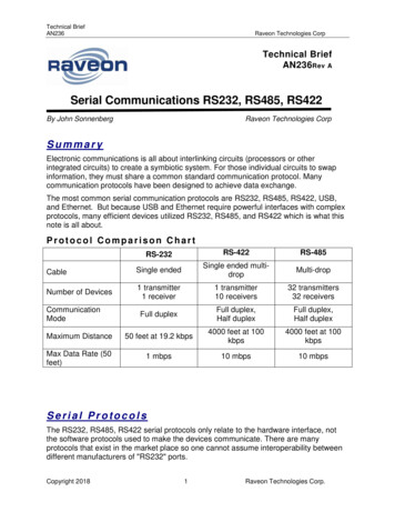
USB-i485 ConverterRS485/RS422INSTRUCTION MANUAL V1.0x ECE MarkThis is a Class A product. In a domestic environment, this product may cause radio interference in which case the user may be required to takeadequate measures.NOVUS AUTOMATION1/13
12344.14.24.355.15.25.366.16.26.3789SAFETY ALERTS .3PRESENTATION .4DIMENSION .5USB DRIVER INSTALLATION .6WINDOWS.6LINUX .6MAC .6SERIAL PORT (COM PORT) ASSIGNMENT - WINDOWS .7DETERMINATION .7SELECTION .7IMPORTANT RECOMMENDATION .8CONNECTIONS .9HALF-DUPLEX RS485 HALF-DUPLEX (2 WIRES) .9FULL-DUPLEX RS485 FULL-DUPLEX (4 WIRES) .10RS422 .10CONFLICTS WITH OTHER USB DEVICES UNDER WINDOWS .11TECHNICAL SPECIFICATIONS .12WARRANTY .13NOVUS AUTOMATION2/13
1SAFETY ALERTSThe symbols below are used in the device and throughout this manual to draw the user’s attention to important information related to device safetyand use.CAUTIONRead the manual fully before installing andoperating the device.CAUTION OR HAZARDRisk of electric shock.ATTENTIONMaterial sensitive to static charge. Checkprecautions before handling.All safety recommendations appearing in this manual must be followed to ensure personal safety and prevent damage to the instrument or system.If the instrument is used in a manner other than that specified in this manual, the device’s safety protections may not be effective.NOVUS AUTOMATION3/13
2PRESENTATIONThe USB-i485 Converter is a cost-effective way to convert RS485 or RS422 industrial buses to a USB interface. When connected to a PC USBport the USB-i485 Converter is automatically detected and is installed as a native COM port, which is compatible with any existing serialcommunication application.Multiple modules can be installed when using USB hubs thus allowing a hassle-free configuration of a multi serial system without any IRQ or DMAconfiguration.1500 Vdc isolation between the USB port and RS485/RS422 protects the PC from spikes or possible misconnections in the communication bus.The USB-i485 Converter can be configured for four-wire (Full Duplex) RS422 and RS485 or two-wire (Half Duplex) networks. When operating intwo-wire RS485 the data transfer control is automatically done by the converter. Two independent and isolated RS485 networks can be supportedby one USB-i485 Converter thus duplicating the possible number of remote devices.NOVUS AUTOMATION4/13
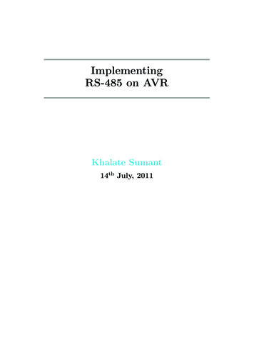
3DIMENSIONThe USB-i485 Converter has the following dimensions:Fig. 01 – USB-i485 ConverterNOVUS AUTOMATION5/13
4USB DRIVER INSTALLATIONThe following installation steps may be slightly different depending on your PC configuration and Windows version. Follow the Wizard instructionsand use the following steps and figures to select the correct installation options.4.1WINDOWSa) Run the driver file available on our website.b) Connect the module to a PC USB port. Windows will detect the new hardware and will try to install it automatically.c) After a few seconds, an installation error message will be displayed on the bottom right corner of the screen. This error has to do with the factthat Windows cannot recognize any device that has not been previously subscribed by Microsoft.d) Open the Device Manager screen and search for the “F232R USB UART” device in the “Other Devices” category. Double-click it and click onthe “Update Driver.” button.e) Choose the “Browse my computer for driver software” option.f) Select the “Drivers\Windows”. Let the “Include subfolders” selected.g) If a window asking whether you want to install this driver pops up, choose to install.h) Wait a few more seconds. A window displaying the installation success will be shown.4.2LINUXSince version 2.4.20, the necessary driver for the converter to work properly is already included in kernel.Once you connect the converter to a PC USB port, the following modules should be loaded (they must be in the kernel list of modules): ftdi sio(specific driver of the converter); usbserial(generic driver for USB-Serial conversion); usbcore(basic driver for USB devices).4.3MACSee the documentation on the device page on our website. The Virtual Driver COM file provides information about how to perform the installation.NOVUS AUTOMATION6/13
5SERIAL PORT (COM PORT) ASSIGNMENT - WINDOWS5.1DETERMINATIONThe serial port associated to the USB-i485 Converter is automatically determined by the operational system a few instants after the USB-i485Converter connection. The user may easily identify or alter the COM port associated to the USB-i485 Converter accessing the Windows "DeviceManager":Control Panel / System / Hardware / Device Manager / COM & LPT PortsIt’s also possible to open the "Device Manager" executing the following command: "devmgmt.msc".After opening the "Device Manager", it's possible to verify which is the Serial Port (COM) associated to the USB-i485 Converter. As it can be seenin Fig. 02, the USB-i485 Converter is associated to COM7.Fig. 02 – COM Port Determination5.2SELECTIONIn case it's necessary to modify the Serial Port (COM) associated to the USB-i485 Converter, select "USB Serial Port (COM X)" where theUSB-i485 Converter is connected. Access "Action/Properties" and, in the "Port Definitions" tab, click Advanced, as shown in Fig. 03. In casethis tab does not appear, the driver was not installed correctly and the software must be reinstalled.In the "Advanced definitions for COMX" window, change the parameter "COM Port Number" for the desired COM, as shown in Fig. 04. Some serialports may be marked as "In Use". Only select one of these ports in case you are sure that it is not being used by another peripheral of yourcomputer.In some situations, the serial ports may be marked as in use even when the associated device is not installed anymore in the computer. In thiscase, it is safe to associate this port to the USB-i485 Converter.Fig. 03 - Accessing the COM port advanced configurationNOVUS AUTOMATION7/13
5.3IMPORTANT RECOMMENDATIONTo improve the communication of the USB interface, it is recommended the configuration of a Latency Timer. This parameter may be modifiedaccessing "Advanced definitions for COMX" window, as shown in Fig. 03.Later it's possible to verify, as shown in Fig. 04, the "Latency Timer (ms)", which must be altered to 4.Fig. 04 - Advanced definitions for COMNOVUS AUTOMATION8/13
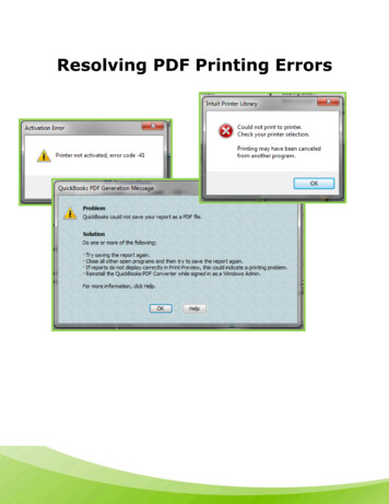
6CONNECTIONSThe appropriate connection to the USB-i485 Converter depends on the type of serial network: RS422, 2-wire RS485 or 4-wire RS485. Thefollowing figure shows a description of all USB-i485 Converter connection terminals.Fig. 05 – Device ConnectionsA shielded twisted-pairs cable is recommended for wiring the communication bus from the converter to all network devices. The shield should begrounded and/or connected to the common terminals of all devices. The minimum recommended wire gauge is 24 AWG (0,2 mm2).Use of a wire connecting all devices common terminals is highly recommended. Damage of the networked devices mayresult if this recommendation is not followed.RS485 or RS422 devices from different vendors or of different models may identify the communication terminals using distinct notation. Thefollowing table shows some of this notations and its equivalence to the USB-i485 Converter.USB-i485 CONNECTION IDENTIFICATIONPOPULAR RS485 AND RS422 CONNECTION IDENTIFICATIONRx ou Tx Rx- ou Tx-DDD1D0BAD D-Table 01 – Identification6.1HALF-DUPLEX RS485 HALF-DUPLEX (2 WIRES)To set this mode of operation, the MOD terminal (pin 4) must be left unconnected.This is the usual RS485 connection. A single twisted pair is used for data transmission and reception. Multiple RS485 devices are connected in asingle bus, as shown in the next figure. Devices from different vendors may use different names for the data signal terminals.In the following figure, different identification schemes are presented for each device, with the proper connection to the USB-i485 Converter.RS485 devices can be connected to either bus 1 or 2.Fig. 06 – Half-Duplex RS485 (2 wires)The common terminal (GND – pin 5) must be connected to the corresponding terminals of all network devices, to ensure the same potential in alldevices. If a common wire is not connected to all devices, all must be properly grounded according to the manufacturer recommendation. For theUSB-i485 Convert, the proper grounding terminal is pin 5 (GND).The need to install termination resistors depends on the total length of the communication bus and the communication speed (Baud Rate). TheUSB-i485 Convert has built-in termination resistors, which can be installed by wiring terminals RT1 (8) or RT2 (3) as shown in dashed lines in thelast figure.For additional information in grounding, common wire and termination resistors, read the document RS485 & RS422 Basic, available on ourwebsite www.novusautomation.com for download.NOVUS AUTOMATION9/13
6.2FULL-DUPLEX RS485 FULL-DUPLEX (4 WIRES)To set this mode of operation, the MOD terminal (pin 4) must be connected to terminal GND (pin 5).In this mode two pairs of wires are used. Data from the USB-i485 Convert to the networked devices are transmitted through one pair, and the otherpair carries data from the devices to the USB-i485 Convert. Multiple devices are connected as shown in the next figure.Fig. 07 – Full-Duplex RS485 (4 wires)The common terminal (GND – pin 4) must be connected to the corresponding terminals of all network devices, to ensure the same potential in alldevices. If a common wire is not connected to all devices, all must be properly grounded according to the manufacturer recommendation. For theUSB-i485 Converter, the proper grounding terminal is pin 5 (GND).The need to install termination resistors depends on the total length of the communication bus and the communication speed (baud rate). TheUSB-i485 Converter has a built-in termination resistor, which can be installed by wiring terminal RT2 (3) as shown in dashed lines in the lastfigure.For additional information in grounding, common wire and termination resistors, read the document RS485 & RS422 Basic, available on ourwebsite www.novusautomation.com for download.6.3RS422Full-Duplex RS485 specification supersedes RS422. The same connection instructions shown for Full-Duplex RS485 apply for RS422 connection.NOVUS AUTOMATION10/13
7CONFLICTS WITH OTHER USB DEVICES UNDER WINDOWSInstallation of the USB driver for the USB-i485 converter may result in conflicts with existing USB devices in the computer (mouse or otherSerial/USB devices, for example). In this case, follow the procedure below to restore functionality of the affected device:o to the Windows Control Panel and open the USB-i485 Converter properties in:Control Panel / System / Hardware / Device Manager / Ports (COM & LPT)Select the desired “USB Serial Port” device, click with the right mouse button and select “Properties”. Select “Port Settings” and click on the“Advanced.” button. Uncheck the “Serial Enumerator” option:Fig. 08 – Serial EnumeratorNOVUS AUTOMATION11/13
8TECHNICAL SPECIFICATIONSComputer InterfaceOperational systemvirtual serial port driverField InterfacesData RateMaximum RS485/RS422cable lengthMaximum number ofdevices in the RS485networkPowerIsolationUSB V1.1 Plug and PlayWindows: Windows 8, 7, Vista, XP, Server 2008, Server 2003, 98, ME, 2000, CE;MAC;Linux 2.4.20 or above.RS485 Half Duplex (dual buses);RS485 Full Duplex;RS422.From 300 bps to 250 kbps.1200 mMaximum number of devices in the RS485 network (unit load devices – 12 kΩ): Half Duplex: 2 x 32 devices; Full Duplex: 32 devices.From the USB post. Consumption: 100 mA.1500 Vcc (1 minute) from USB interface and the RS485/RS422 interface.RS485/RS422 busprotection 60 Vcc, 15 kV ESDUSB ConnectionMini-B connector.A 1.5 m cable with plugs mini-B and A is provided with the device.RS485/422 ConnectorScrew terminal type accepting 1.5 mm² (16 AWG) wires.Operating Environment0 to 50 C, 10 to 90 % relative humidity, non-condensing.Communication protocolJumper selected RS485 / RS422.Flow ControlInternal TerminatingResistorsLEDsAutomatic flow control for RS485 Half Duplex.120 Ohms internal resistors termination enabled by jumpers.Transmission and reception of data.ABS Housing70 x 60 x 18 mm.CertificationsCETable 02 – Technical SpecificationsNOVUS AUTOMATION12/13
9WARRANTYWarranty conditions are available on our website www.novusautomation.com.NOVUS AUTOMATION13/13
NOVUS AUTOMATION 4/13 2 PRESENTATION The USB-i485 Converter is a cost-effective way to convert RS485 or RS422 industrial buses to a USB interface. When connected to a PC USB port the USB-i485 Converter is automatically detected and is installed as a native COM port, which is compatible with any existing serial communication application. Multiple modules can be installed when using USB hubs .