Transcription
AN5027Application noteInterfacing PDM digital microphones usingSTM32 MCUs and MPUsIntroductionDigital MEMS (microelectromechanical systems) microphones target all audio applicationswhere small size, high sound quality, reliability and affordability are key requirements.Their combination of small footprint and noise immunity allows the implementation ofmultiple microphones in a single device, creating an increasing growth of audio in industrialand consumer applications by offering a hands-free human machine interface, noisecancellation, and high quality audio capture.The STM32 32-bit Arm Cortex MCUs and the STM32 Arm Cortex MPUs offer a wideaudio capability with a rich connectivity, including serial and enhanced voice-acquisitioninterfaces allowing the user to easily build solution for microphone-based applications.This document targets digital MEMS microphones having a pulse-density modulated (PDM)output and describe how to connect them in mono and stereo configurations to STM32MCUs and MPUs by using the SPI/I2S, SAI and DFSDM peripherals. It provides guidelinesand examples based on STM32CubeMX and shows how to properly configure the STM32device to acquire and handle raw data from the microphones in order to transform this rawdata into standard data for audio.July 2019AN5027 Rev 21/66www.st.com1
ContentsAN5027Contents1PDM digital microphones overview . . . . . . . . . . . . . . . . . . . . . . . . . . . . . 71.1Sound acquisition overview . . . . . . . . . . . . . . . . . . . . . . . . . . . . . . . . . . . . 71.2PDM digital microphone block diagram . . . . . . . . . . . . . . . . . . . . . . . . . . . 81.3Basic digital microphones connection . . . . . . . . . . . . . . . . . . . . . . . . . . . . 91.4PDM and PCM signals . . . . . . . . . . . . . . . . . . . . . . . . . . . . . . . . . . . . . . . 121.521.4.1Pulse density modulation (PDM) . . . . . . . . . . . . . . . . . . . . . . . . . . . . . . 121.4.2Pulse code modulation (PCM) . . . . . . . . . . . . . . . . . . . . . . . . . . . . . . . . 121.4.3PDM to PCM conversion . . . . . . . . . . . . . . . . . . . . . . . . . . . . . . . . . . . . 13Acoustic parameters . . . . . . . . . . . . . . . . . . . . . . . . . . . . . . . . . . . . . . . . . 131.5.1Sensitivity . . . . . . . . . . . . . . . . . . . . . . . . . . . . . . . . . . . . . . . . . . . . . . . . 131.5.2Signal-to-noise ratio (SNR) . . . . . . . . . . . . . . . . . . . . . . . . . . . . . . . . . . 131.5.3Acoustic overload point (AOP) . . . . . . . . . . . . . . . . . . . . . . . . . . . . . . . . 141.5.4Power supply rejection ratio (PSRR) . . . . . . . . . . . . . . . . . . . . . . . . . . . 141.6Added value of digital microphones . . . . . . . . . . . . . . . . . . . . . . . . . . . . . 141.7Available ST digital microphones . . . . . . . . . . . . . . . . . . . . . . . . . . . . . . . 15Connecting PDM digital microphones to STM32 MCUs and MPUs . . 162.12.22.3Serial peripheral interface (SPI) /Inter-IC sound (I2S) . . . . . . . . . . . . . . . 162.1.1Mono configuration . . . . . . . . . . . . . . . . . . . . . . . . . . . . . . . . . . . . . . . . 162.1.2Stereo configuration . . . . . . . . . . . . . . . . . . . . . . . . . . . . . . . . . . . . . . . . 18Serial audio interface (SAI) . . . . . . . . . . . . . . . . . . . . . . . . . . . . . . . . . . . 202.2.1Using a single sub-block . . . . . . . . . . . . . . . . . . . . . . . . . . . . . . . . . . . . 202.2.2Using two synchronous SAI sub-blocks . . . . . . . . . . . . . . . . . . . . . . . . . 232.2.3Using PDM interface . . . . . . . . . . . . . . . . . . . . . . . . . . . . . . . . . . . . . . . 24Digital filter for sigma delta modulators (DFSDM) . . . . . . . . . . . . . . . . . . 272.3.12.42.53Clocking considerations . . . . . . . . . . . . . . . . . . . . . . . . . . . . . . . . . . . . . . 282.4.1The digital microphone clock . . . . . . . . . . . . . . . . . . . . . . . . . . . . . . . . . 282.4.2The peripheral clocks . . . . . . . . . . . . . . . . . . . . . . . . . . . . . . . . . . . . . . . 29GPIOs number considerations . . . . . . . . . . . . . . . . . . . . . . . . . . . . . . . . . 31Digital signal processing . . . . . . . . . . . . . . . . . . . . . . . . . . . . . . . . . . . . 323.12/66Stereo configuration . . . . . . . . . . . . . . . . . . . . . . . . . . . . . . . . . . . . . . . . 28PDM audio software decoding library . . . . . . . . . . . . . . . . . . . . . . . . . . . . 32AN5027 Rev 2
AN5027Contents3.23.1.1Overview . . . . . . . . . . . . . . . . . . . . . . . . . . . . . . . . . . . . . . . . . . . . . . . . 323.1.2Digital data flow . . . . . . . . . . . . . . . . . . . . . . . . . . . . . . . . . . . . . . . . . . . 323.1.3Digital signal processing . . . . . . . . . . . . . . . . . . . . . . . . . . . . . . . . . . . . 33DFSDM filters for digital signal processing . . . . . . . . . . . . . . . . . . . . . . . . 343.2.14Digital data flow: acquisition and processing . . . . . . . . . . . . . . . . . . . . . 34Examples of configuration based on STM32CubeMX . . . . . . . . . . . . . 354.14.24.34.4Example 1: Interfacing digital microphones in mono orstereo mode with I2S, SPI or a single SAI sub-block . . . . . . . . . . . . . . . . 354.1.1Hardware configuration using STM32CubeMX . . . . . . . . . . . . . . . . . . . 354.1.2Adding PDM software decoding library middleware files . . . . . . . . . . . . 47Example 2: Interfacing digital microphones in stereo modewith SAI using two synchronous sub-blocks . . . . . . . . . . . . . . . . . . . . . . 484.2.1SAI configuration using STM32CubeMX . . . . . . . . . . . . . . . . . . . . . . . . 484.2.2Adding PDM software decoding library middleware files . . . . . . . . . . . . 53Example 3: Interfacing digital microphones in stereo modewith SAI using PDM interface . . . . . . . . . . . . . . . . . . . . . . . . . . . . . . . . . . 534.3.1SAI configuration using STM32CubeMX . . . . . . . . . . . . . . . . . . . . . . . . 534.3.2Adding PDM software decoding library middleware files . . . . . . . . . . . . 57Example 4: Interfacing digital microphones using DFSDM . . . . . . . . . . . 584.4.1DFSDM configuration using STM32CubeMX . . . . . . . . . . . . . . . . . . . . 585Conclusion . . . . . . . . . . . . . . . . . . . . . . . . . . . . . . . . . . . . . . . . . . . . . . . . 646Revision history . . . . . . . . . . . . . . . . . . . . . . . . . . . . . . . . . . . . . . . . . . . 65AN5027 Rev 23/663
List of tablesAN5027List of tablesTable 1.Table 2.Table 3.Table 4.Table 5.Table 6.Table 7.Table 8.Table 9.Table 10.Table 11.Table 12.Table 13.Table 14.Table 15.Table 16.4/66DOUT signal pattern selection . . . . . . . . . . . . . . . . . . . . . . . . . . . . . . . . . . . . . . . . . . . . . . . 9Pin description . . . . . . . . . . . . . . . . . . . . . . . . . . . . . . . . . . . . . . . . . . . . . . . . . . . . . . . . . . . 9Added value of digital microphone . . . . . . . . . . . . . . . . . . . . . . . . . . . . . . . . . . . . . . . . . . . 14ST digital microphones . . . . . . . . . . . . . . . . . . . . . . . . . . . . . . . . . . . . . . . . . . . . . . . . . . . . 15Recommended IO lines versus the number digital microphonesto be connected . . . . . . . . . . . . . . . . . . . . . . . . . . . . . . . . . . . . . . . . . . . . . . . . . . . . . . . . . 24Applications examples and the associated microphone clock frequency . . . . . . . . . . . . . . 29Hardware used to connect one digital microphone. . . . . . . . . . . . . . . . . . . . . . . . . . . . . . . 31Hardware used to connect two digital microphones . . . . . . . . . . . . . . . . . . . . . . . . . . . . . . 31Hardware used to connect four digital microphones. . . . . . . . . . . . . . . . . . . . . . . . . . . . . . 31I2S2 clock configuration and accuracy . . . . . . . . . . . . . . . . . . . . . . . . . . . . . . . . . . . . . . . . 36SPI clock configuration and accuracy . . . . . . . . . . . . . . . . . . . . . . . . . . . . . . . . . . . . . . . . . 39Clock configuration and accuracy . . . . . . . . . . . . . . . . . . . . . . . . . . . . . . . . . . . . . . . . . . . . 42SAI clock configuration and accuracy . . . . . . . . . . . . . . . . . . . . . . . . . . . . . . . . . . . . . . . . . 49DFSDFM filter order values . . . . . . . . . . . . . . . . . . . . . . . . . . . . . . . . . . . . . . . . . . . . . . . . 60DFSDM clock configuration accuracy values . . . . . . . . . . . . . . . . . . . . . . . . . . . . . . . . . . . 63Document revision history . . . . . . . . . . . . . . . . . . . . . . . . . . . . . . . . . . . . . . . . . . . . . . . . . 65AN5027 Rev 2
AN5027List of figuresList of figuresFigure 1.Figure 2.Figure 3.Figure 4.Figure 5.Figure 6.Figure 7.Figure 8.Figure 9.Figure 10.Figure 11.Figure 12.Figure 13.Figure 14.Figure 15.Figure 16.Figure 17.Figure 18.Figure 19.Figure 20.Figure 21.Figure 22.Figure 23.Figure 24.Figure 25.Figure 26.Figure 27.Figure 28.Figure 29.Figure 30.Figure 31.Figure 32.Figure 33.Figure 34.Figure 35.Figure 36.Figure 37.Figure 38.Figure 39.Figure 40.Figure 41.Figure 42.Figure 43.Figure 44.Example of sound acquisition in audio application . . . . . . . . . . . . . . . . . . . . . . . . . . . . . . . . 7Typical PDM digital MEMS microphone block diagram . . . . . . . . . . . . . . . . . . . . . . . . . . . . 8Mono configuration - Generating data on right channel . . . . . . . . . . . . . . . . . . . . . . . . . . . . 9Right channel data pattern . . . . . . . . . . . . . . . . . . . . . . . . . . . . . . . . . . . . . . . . . . . . . . . . . 10Mono configuration - Generating data on left channel . . . . . . . . . . . . . . . . . . . . . . . . . . . . 10Left channel data pattern . . . . . . . . . . . . . . . . . . . . . . . . . . . . . . . . . . . . . . . . . . . . . . . . . . 10Stereo configuration: Sharing one data line . . . . . . . . . . . . . . . . . . . . . . . . . . . . . . . . . . . . 11Stereo configuration data pattern . . . . . . . . . . . . . . . . . . . . . . . . . . . . . . . . . . . . . . . . . . . . 11PDM signal . . . . . . . . . . . . . . . . . . . . . . . . . . . . . . . . . . . . . . . . . . . . . . . . . . . . . . . . . . . . . 12PCM signal . . . . . . . . . . . . . . . . . . . . . . . . . . . . . . . . . . . . . . . . . . . . . . . . . . . . . . . . . . . . . 13Connecting one digital microphone to SPI or I2S in mono configuration . . . . . . . . . . . . . . 17Connecting two digital microphone to SPI block in stereo configuration . . . . . . . . . . . . . . 18Stereo mode timing diagram. . . . . . . . . . . . . . . . . . . . . . . . . . . . . . . . . . . . . . . . . . . . . . . . 19Connecting one digital microphone to SAI in mono configuration . . . . . . . . . . . . . . . . . . . 20Connecting two digital microphones to SAI in stereo configurationusing a SAI sub-block and a timer . . . . . . . . . . . . . . . . . . . . . . . . . . . . . . . . . . . . . . . . . . . 22Connecting two digital microphone to SAI in stereo configurationusing two synchronous SAI sub-blocks . . . . . . . . . . . . . . . . . . . . . . . . . . . . . . . . . . . . . . . 23PDM interface capability on interfacing up to four microphone pairs . . . . . . . . . . . . . . . . . 25Data format when using the SAI PDM interface with a slot size of 32 bits,and 8 microphones . . . . . . . . . . . . . . . . . . . . . . . . . . . . . . . . . . . . . . . . . . . . . . . . . . . . . . . 26Data format when using the SAI PDM interface with a slot size of 8 bits,and 8 microphones . . . . . . . . . . . . . . . . . . . . . . . . . . . . . . . . . . . . . . . . . . . . . . . . . . . . . . . 26DFSDM capability to interface up to 4 digital microphones . . . . . . . . . . . . . . . . . . . . . . . . 27Stereo configuration . . . . . . . . . . . . . . . . . . . . . . . . . . . . . . . . . . . . . . . . . . . . . . . . . . . . . . 28Bus and kernel clock topology for SPI . . . . . . . . . . . . . . . . . . . . . . . . . . . . . . . . . . . . . . . . 30Bus and kernel clock topology for SAI and DFSDM . . . . . . . . . . . . . . . . . . . . . . . . . . . . . . 30Digital data acquisition and processing (block diagram). . . . . . . . . . . . . . . . . . . . . . . . . . . 33Digital signal processing . . . . . . . . . . . . . . . . . . . . . . . . . . . . . . . . . . . . . . . . . . . . . . . . . . . 33Digital data acquisition and processing using DFSDM (block diagram) . . . . . . . . . . . . . . . 34I2S GPIO pin configuration . . . . . . . . . . . . . . . . . . . . . . . . . . . . . . . . . . . . . . . . . . . . . . . . . 36I2S2 clock configuration . . . . . . . . . . . . . . . . . . . . . . . . . . . . . . . . . . . . . . . . . . . . . . . . . . . 37I2S configuration . . . . . . . . . . . . . . . . . . . . . . . . . . . . . . . . . . . . . . . . . . . . . . . . . . . . . . . . . 37I2S parameter settings . . . . . . . . . . . . . . . . . . . . . . . . . . . . . . . . . . . . . . . . . . . . . . . . . . . . 38I2S DMA settings . . . . . . . . . . . . . . . . . . . . . . . . . . . . . . . . . . . . . . . . . . . . . . . . . . . . . . . . 38SPI GPIO and pin configuration . . . . . . . . . . . . . . . . . . . . . . . . . . . . . . . . . . . . . . . . . . . . . 39SPI clock configuration . . . . . . . . . . . . . . . . . . . . . . . . . . . . . . . . . . . . . . . . . . . . . . . . . . . . 39SPI configuration . . . . . . . . . . . . . . . . . . . . . . . . . . . . . . . . . . . . . . . . . . . . . . . . . . . . . . . . 40SPI parameter setting . . . . . . . . . . . . . . . . . . . . . . . . . . . . . . . . . . . . . . . . . . . . . . . . . . . . . 40SPI DMA settings . . . . . . . . . . . . . . . . . . . . . . . . . . . . . . . . . . . . . . . . . . . . . . . . . . . . . . . . 41SAI GPIO and pin configuration . . . . . . . . . . . . . . . . . . . . . . . . . . . . . . . . . . . . . . . . . . . . . 41SAI clock configuration at 16 kHz for mono mode . . . . . . . . . . . . . . . . . . . . . . . . . . . . . . . 42SAI configuration . . . . . . . . . . . . . . . . . . . . . . . . . . . . . . . . . . . . . . . . . . . . . . . . . . . . . . . . 43SAI parameter setting . . . . . . . . . . . . . . . . . . . . . . . . . . . . . . . . . . . . . . . . . . . . . . . . . . . . . 44SAI DMA settings . . . . . . . . . . . . . . . . . . . . . . . . . . . . . . . . . . . . . . . . . . . . . . . . . . . . . . . . 45DMA request settings . . . . . . . . . . . . . . . . . . . . . . . . . . . . . . . . . . . . . . . . . . . . . . . . . . . . . 45TIM GPIO and pin configuration . . . . . . . . . . . . . . . . . . . . . . . . . . . . . . . . . . . . . . . . . . . . . 46TIM configuration . . . . . . . . . . . . . . . . . . . . . . . . . . . . . . . . . . . . . . . . . . . . . . . . . . . . . . . . 46AN5027 Rev 25/666
List of figuresFigure 45.Figure 46.Figure 47.Figure 48.Figure 49.Figure 50.Figure 51.Figure 52.Figure 53.Figure 54.Figure 55.Figure 56.Figure 57.Figure 58.Figure 59.Figure 60.Figure 61.Figure 62.Figure 63.Figure 64.Figure 65.Figure 66.6/66AN5027TIM parameter settings . . . . . . . . . . . . . . . . . . . . . . . . . . . . . . . . . . . . . . . . . . . . . . . . . . . . 47SAI GPIO and pin configuration . . . . . . . . . . . . . . . . . . . . . . . . . . . . . . . . . . . . . . . . . . . . . 48SAI clock configuration . . . . . . . . . . . . . . . . . . . . . . . . . . . . . . . . . . . . . . . . . . . . . . . . . . . . 49SAI parameter settings . . . . . . . . . . . . . . . . . . . . . . . . . . . . . . . . . . . . . . . . . . . . . . . . . . . . 51SAIB parameter settings . . . . . . . . . . . . . . . . . . . . . . . . . . . . . . . . . . . . . . . . . . . . . . . . . . . 52SAI DMA settings . . . . . . . . . . . . . . . . . . . . . . . . . . . . . . . . . . . . . . . . . . . . . . . . . . . . . . . . 52SAI GPIO and pin configuration . . . . . . . . . . . . . . . . . . . . . . . . . . . . . . . . . . . . . . . . . . . . . 53SAI clock configuration for 2 microphones at 16 kHz . . . . . . . . . . . . . . . . . . . . . . . . . . . . . 54SAI configuration . . . . . . . . . . . . . . . . . . . . . . . . . . . . . . . . . . . . . . . . . . . . . . . . . . . . . . . . 54SAI parameter settings . . . . . . . . . . . . . . . . . . . . . . . . . . . . . . . . . . . . . . . . . . . . . . . . . . . . 55SAI DMA settings . . . . . . . . . . . . . . . . . . . . . . . . . . . . . . . . . . . . . . . . . . . . . . . . . . . . . . . . 56CORTEX M7 configuration . . . . . . . . . . . . . . . . . . . . . . . . . . . . . . . . . . . . . . . . . . . . . . . . 56Cortex M7 parameter settings . . . . . . . . . . . . . . . . . . . . . . . . . . . . . . . . . . . . . . . . . . . . . . 57DFSDM GPIO configuration in stereo mode. . . . . . . . . . . . . . . . . . . . . . . . . . . . . . . . . . . . 58DFSDM pin configuration . . . . . . . . . . . . . . . . . . . . . . . . . . . . . . . . . . . . . . . . . . . . . . . . . . 59DFSDM Channel 1 configuration . . . . . . . . . . . . . . . . . . . . . . . . . . . . . . . . . . . . . . . . . . . . 59DFSDM Channel 0 configuration . . . . . . . . . . . . . . . . . . . . . . . . . . . . . . . . . . . . . . . . . . . . 60DFSDM Filter 0 configuration . . . . . . . . . . . . . . . . . . . . . . . . . . . . . . . . . . . . . . . . . . . . . . . 61DFSDM Filter 1 configuration . . . . . . . . . . . . . . . . . . . . . . . . . . . . . . . . . . . . . . . . . . . . . . . 61DFSDM output clock configuration . . . . . . . . . . . . . . . . . . . . . . . . . . . . . . . . . . . . . . . . . . . 62DFSDM DMA setting . . . . . . . . . . . . . . . . . . . . . . . . . . . . . . . . . . . . . . . . . . . . . . . . . . . . . 62DFSDM clock configuration . . . . . . . . . . . . . . . . . . . . . . . . . . . . . . . . . . . . . . . . . . . . . . . . 63AN5027 Rev 2
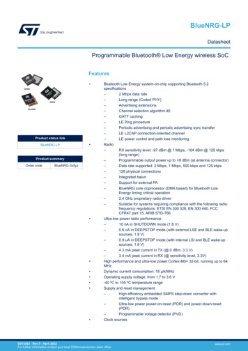
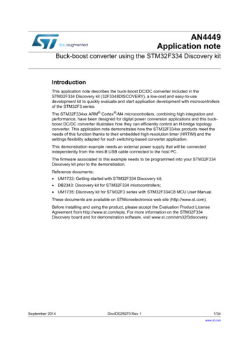
AN50271PDM digital microphones overviewPDM digital microphones overviewThis section provides a brief description of PDM digital microphones and presents basiccases of interfacing them with STM32 devices. STM32 MCUs and MPUs are Arm (a) baseddevices.1.1Sound acquisition overviewThe digital MEMS microphone is a sensor that convert acoustic pressure waves into adigital signal. The STM32 MCUs and MPUs acquire digital data from the microphone(s)through particular peripherals to be processed and transformed into data standard for audio.The audio data is then handled by the microcontroller according to the targeted audioapplication.Figure 1. Example of sound acquisition in audio applicationData acquisition and processingVoice recognitionSTM32 MCUSound waveAudioapplicationHigh qualityaudio recordDigital MEMS MicrophoneSound acquisitionNoise cancellationMS47180V1a. Arm is a registered trademark of Arm Limited (or its subsidiaries) in the US and/or elsewhere.AN5027 Rev 27/6664
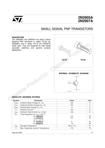
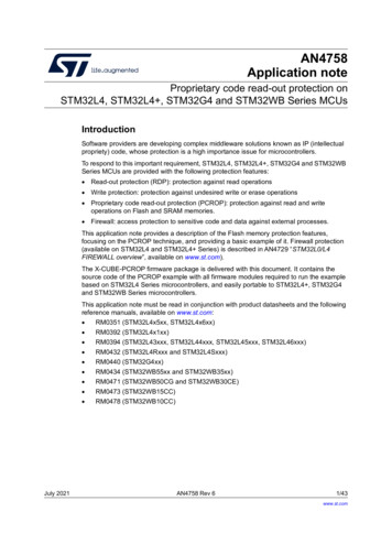
PDM digital microphones overview1.2AN5027PDM digital microphone block diagramThe main parts in a digital microphone are a MEMS transducer, an amplifier and a PDMmodulator.Figure 2. Typical PDM digital MEMS microphone block VddCHANNELSELECTDOUTLRGNDMS47147V1MEMS transducerThe MEMS transducer is a variable capacitance that converts the change into air pressurecaused by sound waves to a voltage.AmplifierThe amplifier buffers the voltage provided by the MEMS transducer, and provides asufficiently strong signal to the PDM modulator.PDM modulatorPDM modulator converts the buffered analog signal into a serial pulse density modulatedsignal. The clock input (CLK) is used to control the PDM modulator. The clock frequencyrange for ST digital microphones is from 1 MHz to 3.25 MHz. This frequency defines thesampling rate at which the amplifier’s analog output signal is sampled to produce a discretetime representation (PDM bitstream).Channel selectThe microphone’s output is driven to the proper level on a selected clock edge and thengoes into a high impedance state for the other half of the clock cycle. The channel selectdefines the clock edge on which the digital microphone outputs valid data. The LR pin mustbe connected to Vdd or GND.Table 1 shows how to select the DOUT signal pattern.8/66AN5027 Rev 2
AN5027PDM digital microphones overviewTable 1. DOUT signal pattern selectionDOUTLRCLK lowCLK highGNDValid dataHigh impedanceVddHigh impedanceValid dataPowerPower delivers Vdd and GND supplies to the different digital microphone’s components. Thepower supply should be properly provided to the microphone since any ripple can generatenoise on the output.Pin descriptionTable 2. Pin description1.3Pin nameFunctionDirectionVdd3.3 V power supplyInputGND0VInputLRLeft/right selectionInputCLKSynchronization clockInputDOUTLeft/righ PDM data outputOutputBasic digital microphones connectionMono modeIn this mode the LR pin can be either connected to Vdd or to GND.LR pin is connected to VddFigure 3. Mono configuration - Generating data on right channelVddSTM32LRDATADATA INPUTDOUTCLKCLOCK OUTPUTMS47148V1On the rising edge of the clock, the microphone generates valid data for half of the clockperiod, then goes into a high impedance state for the other half.AN5027 Rev 29/6664
PDM digital microphones overviewAN5027Figure 4. Right channel data patternCLKDATAValid DataHIGH ZValid DataHIGH ZHIGH ZMS47149V1LR pin is connected to GNDFigure 5. Mono configuration - Generating data on left channelSTM32DATADATA INPUTDOUTCLKLRGNDCLOCK OUTPUTMS47150V1On the falling edge of the clock, the microphone generates valid data for half of the clockperiod, then goes into a high impedance state for the other half.Figure 6. Left channel data patternCLKDATAValid DataValid DataHIGH ZValid DataHIGH ZMS47151V110/66AN5027 Rev 2
AN5027PDM digital microphones overviewStereo configurationFigure 7. Stereo configuration: Sharing one data lineVddLRSTM32DATADATA INPUTDATA RDOUTCLKCLOCK OUTPUTCLKDATA LDOUTLRGNDData rightData leftMS47152V1Two different digital MEMS microphones are connected on the same data line, configuringthe first to generate valid data on the rising edge of the clock by setting the LR pin to Vddand the other on the falling edge by setting the LR pin to GND.Figure 8. Stereo configuration data patternCLKDATA RHIGH ZRHIGH ZRDATA LLHIGH ZLHIGH ZLDATALRLRLHIGH ZMS47153V1AN5027 Rev 211/6664
PDM digital microphones overviewAN50271.4PDM and PCM signals1.4.1Pulse density modulation (PDM)PDM is a form of modulation used to represent an analog signal in the digital domain. It is ahigh frequency stream of 1-bit digital samples. In a PDM signal, the relative density of thepulses corresponds to the analog signal's amplitude. A large cluster of 1s correspond to ahigh (positive) amplitude value, when a large cluster of 0s would correspond to a low(negative) amplitude value, and alternating 1s and 0s would correspond to a zero amplitudevalue.Figure 9. PDM signal10-1Analog signal1.4.2PDM signalMS47154V1Pulse code modulation (PCM)In the PCM signal, specific amplitude values are encoded into pulses.A PCM stream has two basic properties that determine the stream's fidelity to the originalanalog signal: the sampling rate the bit depthThe sampling rate is the number of samples of a signal that are taken per second torepresent it digitally. The bit depth determines the number of bits of information in eachsample.12/66AN5027 Rev 2
AN5027PDM digital microphones overviewFigure 10. PCM signal1514131211109876543Analog signalPCM signal210MS47155V11.4.3PDM to PCM conversionIn order to convert the PDM stream into PCM samples, the PDM stream needs to be filteredand decimated.In the decimation stage, the sampling rate of the PDM signal is reduced to the targetedaudio sampling rate (16 kHz for example). By selecting 1 of each M samples, the samplerate is reduced by a factor of M. Therefore, the PDM data frequency (which is the frequencyof the microphone clock) is M times the target audio sampling frequency needed in anapplication, where M is the decimation factor.PDM frequency Audio sampling frequency decimation factorThe decimation factor is generally in the range of 48 to 128.The decimation stage is preceded by a low-pass filter to avoid distortion from aliasing.1.5Acoustic parameters1.5.1SensitivityThe sensitivity is the level of the electrical signal (expressed in dBFS) that the digitalmicrophone outputs for a given acoustic reference signal.Generally the sensitivity of a microphone is given using a tone of 1 kHz, at 1 Pa (or 94dBSPL) as reference signal.1.5.2Signal-to-noise ratio (SNR)The SNR specifies the ratio between the reference signal (94 dBSPL@1kHz) and theamount of residual noise at the microphone output.Higher SNR offers enhanced voice clarity as well as far-end (hands-free) intelligibility.AN5027 Rev 213/6664
PDM digital microphones overview1.5.3AN5027Acoustic overload point (AOP)The AOP is the maximum acoustic signal, which the microphone can capture withacceptable distortion (some specifications allow up to 10% in terms of distortion at theacoustic overload point).1.5.4Power supply rejection ratio (PSRR)The PSRR specification quantifies the capability of the microphone to reject noise relative topower supply changes.1.6Added value of digital microphonesTable 3. Added value of digital microphoneFeature14/66Added valueImmunity to RF noise andelectromagnetic interference (EMI)– Less integration effortAnalog signal conditioning notrequired– Easier application design– Direct interface to codecs with digital microphonesinterface– Stereo mode needs only one data line– Significant saving on PCB area with more microphones insystem– Flexibility to add additional microphones into theapplicationRobust digital transmission– Easy MEMS positioning on application system– Standard digital conditioning– Allows audio enhancement integration for stereo capture,noise cancellation and beam formingAN5027 Rev 2
AN50271.7PDM digital microphones overviewAvailable ST digital microphonesTable 4 shows the available ST digital microphone.Table 4. ST digital microphonesPart numberTop/bottomportSupply 02Bottom1.64 to 3.662.6-26120MP34DT01-MTop1.64 to 3.661-26120MP34DT02Top1.64 to 3.660-26120MP34DT04Top1.6 to 3.664-26120MP34DT04-C1Top1.6 to 3.664-26120MP34DT05Top1.6 to 3.664-26122.5MP45DT02-MTop1.64 to 3.661-26120AN5027 Rev 215/6664
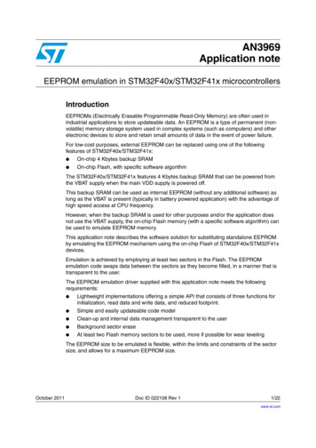
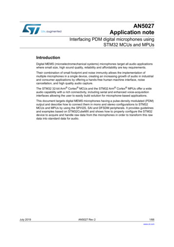
Connecting PDM digital microphones to STM32 MCUs and MPUs2AN5027Connecting PDM digital microphones to STM32MCUs and MPUsThis section describes how to connect digital MEMS microphones to the SPI/ I2S, SAI andDFSDM peripherals embedded in STM32 MCUs and MPUs in both mono and stereoconfigurations.2.1Serial peripheral interface (SPI) /Inter-IC sound (I2S)The STM32 MCUs and MPUs offer a serial peripheral interface block named SPI. Some ofthese SPI blocks also offer the possibility to use the Inter-IC sound audio protocol (I2S). Inaddition, the STM32 devices offer two versions of the SPI block, in this document, the oldestversion is named SPI-V1, and latest version is named SPI-V2. When we refer to SPI block itmeans indifferently SPI-V1 or SPI-V2.The SPI-V2 is currently available on STM32H7 Series.It is possible to connect one or two digital microphones to a SPI block by either using theSPI or I2S protocol.2.1.1 The SPI protocol provides simple communication interface allowing themicrocontrollers to communicate with external devices. The I2S protocol is widely used to transfer audio data from a microcontroller/DSP(digital signal processor) to an audio codec, in order to play melodies or to capturesound from a microphone.Mono configurationA single digital microphone is connected to the SPI block. The SPI block can be configuredeither in SPI or in I2S mode.In both cases, the SPI block is configured in master receiver mode. In this mode, the peripheral provides the clock to the digital microphone. The audio samples are acquired throughthe serial data pin.16/66AN5027 Rev 2
AN5027Connecting PDM digital microphones to STM32 MCUs and MPUsFigure 11. Connecting one digital microphone to SPI or I2S in mono configurationSTM32M1L/RI2Sx SDHalf-DuplexDOUTPDM dataSPIGNDCLK(in I2S mode)I2Sx CKMaster ReceiverPDM clockSTM32M1SPIx MISOSimplexL/RDOUTVddorGNDPDM dataSPICLK(in SPI mode)SPIx SCKMaster ReceiverPDM clockPDM clockMSv48085V1If the SPI protocol is used, the L/R channel selection (LR) pin of the microphone can be connected either to Vdd or to GND. The SPI clock polarity shall be aligned with the configuration of L/R input. If L/R GND, then the SPI shall sample the incoming data using the rising edge ofSPIx SCK, If L/R Vdd, then the SPI shall sample the incoming data using the falling edge ofSPIx SCK,If the I2S protocol is used, it is recommended to set the L/R channel selection (LR) pin of themicrophone to GND. By default the I2S protocol samples the incoming data using the risingedge of I2Sx CK. Note that the SPI-V2 block also offers the possibility to configure the sampling edge for the I2S protocol.Data formatThe samples acquired by the SPI block in I2S or SPI mode can be stored into the memoryusing either DMA or interrupt signaling.The receive data register (SPIx DR) provides contiguous bits from the microphone likeshown in the example hereafter for a 16-bit format:Bit:1514131211.0Content:M1 bNM1 bN 1M1 bN 2M1 bN 3M1 bN 4.M1 bN 15M1 bxx represents the data bits from the digital microphone 1, and M1 bN is the older bit.Note:The bit order of the received samples can be reversed if the interface is programmed in LSBfirst instead of MSB first. Peripherals generally support various data size which are notdetailed here.AN5027 Rev 217/6664
Connecting PDM digital microphones to STM32 MCUs and MPUs2.1.2AN5027Stereo configurationTwo digital microphones can be connected to the SPI block using a timer. The SPI block canbe configured either in SPI or in I2S mode.In both cases, the SPI block is configured in master receiver mode. In this configuration, theSPI peripheral operates at twice the microphone frequency in order to read the data provided by both microphones, on the falli
July 2019 AN5027 Rev 2 1/66 1 AN5027 Application note Interfacing PDM digital microphones using STM32 MCUs and MPUs Introduction Digital MEMS (microelectromechanical systems) microphones target all audio applications