Transcription
AN5715Application noteG3-PLC Hybrid PLC & RF SW packageIntroductionThis document describes the software architecture and implementation of the host controller application firmware exampleincluded in the STSW-ST8500GH software package.The package provides the software ecosystem for ST’s G3-PLC Hybrid PLC & RF connectivity technology evaluation, basedon the ELVKST8500GH868, EVLKST8500GH915 kits that include all the functions required for plug-and-play communicationnetworking.The host controller application firmware example for STM32G070RB, based on FreeRTOS, allows testing the PLC and RFcommunication exploiting the IPv6 layer interface of the ST8500 modem. The G3-PLC Hybrid PLC & RF communication stackhas full flexibility to be configured in any of the available bandplans for both PLC (CEN-A, CEN-B or FCC) and RF (according tothe RF Sub-GHz module selection).Messages between two nodes in the PLC & RF hybrid network are sent over the best available medium: PLC or RF. The mediaselection for each link in the network is done automatically and adjusted dynamically, enabling highly efficient hybrid meshnetworking.The ST hybrid PLC & RF solution is based on open standards and enables seamless integration into existing G3-PLC networksand adoption in multiple applications and systems.AN5715 - Rev 2 - March 2022For further information contact your local STMicroelectronics sales office.www.st.com
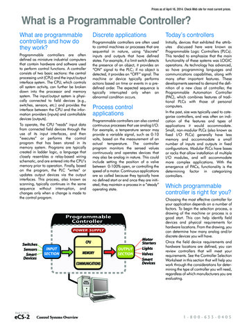
AN5715G3-PLC Hybrid PLC & RF software solution overview1G3-PLC Hybrid PLC & RF software solution overview1.1What is the G3-PLC Hybrid PLC & RF?The G3-PLC Hybrid is the first industry hybrid communication standard offering extended capabilities for SmartGrid and IoT applications in one seamlessly managed network over both wired and wireless media.The hybrid protocol stack is built using open standard IEEE 802.15.4-2015 in addition to the existing G3-PLCprotocol. Each device in the mesh network can use PLC as well as RF for communication. Depending on theactual conditions in the field, messages between two devices are sent over the most reliable channel available.The channel selection for each link in the network is done automatically and adjusted dynamically.In many network conditions, none of the communication technologies can consistently achieve connectivity 99% on their own. The hybrid solution maximizes coverage and connectivity, avoiding the high cost that wouldbe associated to deployment of a different solution to achieve the remaining 1% connectivity. The G3-PLCHybrid profile can provide a more efficient and cost-effective solution for smart grids, smart cities and industrialapplications.The G3-PLC Hybrid profile is: fully compatible and interoperable with existing G3-PLC implementations, so it is possible to mix hybrid andnon-hybrid nodes in the same network; available for all PLC bandplans and supporting a wide range of non-licensed Sub-GHz bands worldwide.1.2Protocol basicsLayer 1Layer 2Layer 3Figure 1. G3 Hybrid PLC & RF protocol stackIPv66LoWPANLBPLOADngHybrid Abstraction LayerPLC MACRF MACPLC PHYRF PHYThe G3-PLC Hybrid PLC & RF protocol stack (see Figure 1) is based on the well-known G3-PLC protocolstandard. To get the best from the two communication technologies involved, Narrow-Band PLC and Sub-GHzRF, the existing G3-PLC MAC layer has been replicated (and adapted) on top of the RF PHY, and a HybridAbstraction Layer has been developed on top of the two MAC layers, to guarantee seamless integration of thetwo media in one single managed network.AN5715 - Rev 2page 2/32
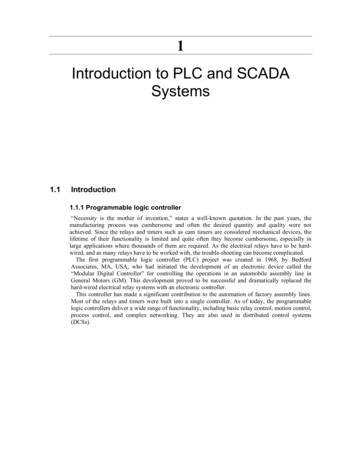
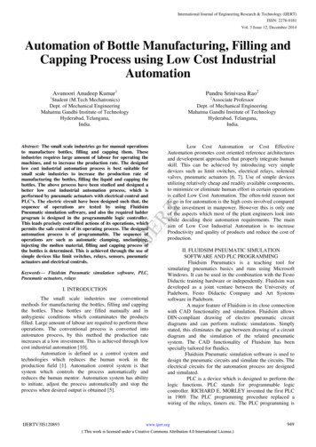
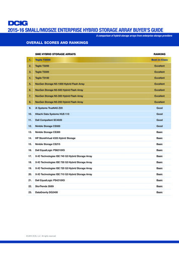
AN5715Supported Hardware and evaluation boardsThe principle of operation is quite simple: each node in a network having hybrid connectivity decides whichmedium to use to reach better performances and coverage, realizing a hop-by-hop automatic selection which istotally transparent to the end user. At the same time, the high flexibility of the implementation allows to mix hybridnodes with PLC-only and/or RF-only nodes in a single network.Figure 2. Hybrid network exampleDataConcentratorRFPLCActual routeSmartMeter1.3Supported Hardware and evaluation boardsThe ST G3-PLC Hybrid PLC & RF is based on three main devices (ST8500, STLD1 and S2-LP) building togetherthe G3-PLC Hybrid PLC & RF modem, with an STM32 microcontroller for the customer application firmware. The ST8500 programmable power line communication modem system-on-chip is at the heart of the system,implementing the full G3-PLC Hybrid PLC & RF stack down to layer 2 (MAC layer) and the PHY layer of thePLC medium. The S2-LP ultra-low power, high performance, Sub-GHz transceiver implements the PHY layer of the RFmedium and the Sub-GHz RF radio. The STLD1 is the Line Driver for the PLC medium.Figure 3. ST chipset implementing the G3-PLC Hybrid PLC & RF protocol stackPLC LinkPLC Physical LayerApplicationLayerTransport LayerNetwork LayerData Link LayerRF LinkRF Physical LayerThe ST G3-PLC Hybrid PLC & RF implementation can run on several evaluation and development kits. Listedbelow are the ones where the STSW-ST8500GH STM32 firmware described in this document can be usedwithout adaptation. Although the EVALKITST8500-1 can run the same protocol stack in PLC only mode, theSTM32 code provided cannot be used without an adaptation.AN5715 - Rev 2page 3/32
AN5715Supported Hardware and evaluation boardsTable 1. ST8500 G3-PLC Hybrid PLC & RF supported boardsPart numberAN5715 - Rev 2Hybrid supportPLC connectivityRF connectivityEVLKST8500GH868YES0-500 kHz863-870 MHzEVLKST8500GH915YES0-500 kHz860-940 MHzpage 4/32
AN5715The G3-PLC Hybrid PLC & RF software package2The G3-PLC Hybrid PLC & RF software packageThe STSW-ST8500GH contains a software package for the STM32G070RB microcontroller based onSTM32CubeMX V6.3.0 and STM32CubeIDE V1.8.0. The structure of the package is described hereafter (pleaserefer to the specific release note to check if there are changes in your version). NUCLEO-G070RB–\Documents–\Drivers–\G3 rint Applications–\Src–\Startup–\User Applications–NUCLEO G070RB.ioc–STM32G070RBTX FLASH.ldThe \Drivers folder contains CMSIS and STM32 HAL (Hardware Abstraction Layer) files for the selected platform(STM32G070RB microcontroller).The \G3 Applications folder contains all the protocol specific firmware, comprising the API and the G3-PLCapplications.The \Inc and \Src folders contain the source code generated by the STM32CubeMX project and framework code,while the \Middlewares folder contains the FreeRTOS specific source files.The \Modules folder contains the source code for all the modules used in the application.The \Startup folder contains the assembly files responsible for the microcontroller preliminary startup operations(stack pointer setup, filling the BSS section with zeros, system initialization, calling the main function ).The \Print Applications folder contains the files related to the Print task, responsible for the printing operations tothe serial terminal.The \User Applications folder contains the files related to an example of UDP user application: a UDP sender/receiver implementation with its FreeRTOS task, a serial terminal handling and several utility functions.The \Documents folder includes a quick start guide on the User application and the release note of the package;you should check this document to see the changes that have occurred since the last official release.The file NUCLEO G070RB.ioc is the STM32CubeMX project file. You can use it to modify and/or regeneratethe project (to modify the toolchain, the pin assignment, the target STM32 etc.) within the constraints of theSTM32CubeMX environment.The file STM32G070RBTX FLASH.ld is the linker script file. It lists and describes all the memory sectionallocated inside the microcontroller (FLASH and RAM).AN5715 - Rev 2page 5/32
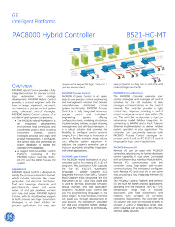
AN5715STM32CubeMX project3STM32CubeMX project3.1Project descriptionWhen first opened, the STM32CubeMX project shows, on the left side, the list of categories the settings referto, while on the right panel the default view is on the STM32 pinout. By moving on the active pins (the ones notgrayed), it is possible to see how they are configured and, when clicking, the alternative settings are shown.Figure 4. STM32CubeMX project initial viewTo see/change the configuration of each peripheral, a side panel is displayed by clicking on a specific peripheralfrom the left side list, with related operating mode and configuration parameters.AN5715 - Rev 2page 6/32
AN5715FreeRTOS subsystemFigure 5. STM32CubeMX project peripheral configuration viewAny information about the STM32CubeMX ecosystem can be found on the st.com website www.st.com (https://www.st.com/content/st com/en/stm32cube-ecosystem.html).3.2FreeRTOS subsystemThe FreeRTOS middleware is generated automatically by STM32CubeMX. The overall FW structure is shown inFigure 6 .AN5715 - Rev 2page 7/32
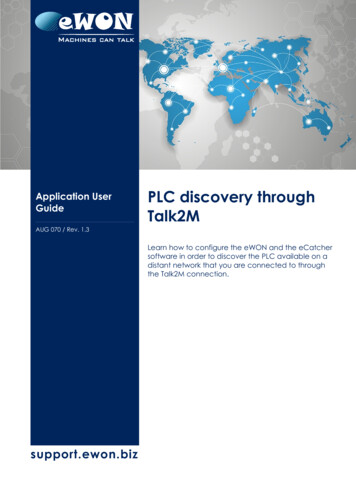
AN5715FreeRTOS subsystemFigure 6. G3-PLC Hybrid PLC & RF SW package architectureThe STM32CubeMX generates the STM32 HAL/CMSIS drivers and configures the middleware (in this case,FreeRTOS).The FreeRTOS configuration parameters can be modified in the FreeRTOS tab under the Middleware sectioninside STM32CubeMX (see Figure 7).For this project, the firmware package STM32Cube FW G0 V1.5.0 has been used as a starting point.AN5715 - Rev 2page 8/32
AN5715UART interface modulesFigure 7. STM32CubeMX FreeRTOS configuration panelThe G3-PLC Hybrid PLC & RF SW project makes use of the CMSIS V2 interface and generates four tasks: The FreeRTOS Default task that blinks an LED to signal it is working and stops in case of fault/stackoverflow. The FreeRTOS G3-PLC task that handles the PLC communication. A complete description of the g3 task isgiven in Section 4 . The FreeRTOS User task that handles an example of UDP application. A complete description of theuser task is given in Section 5 . The FreeRTOS Print task that handles the low-level printing operation to serial terminal. A completedescription of the print task is given in Section 6 .In addition, one event flag, one stream buffer, four semaphores and one mutex are used by the OS: eventSync: event flag used to synchronize all application tasks (User task, G3-PLC task, Print task) aftertheir initialization. hostStreamBuffer: stream buffer used to transfer data to print to the Print task. mutexPrint: mutex used to make sure that only one task sends data to the Print task at a time. semHostTxStart: semaphore used to unblock the Print task whenever a UserTerm LowLevelPrint function iscalled. semHostTxComplete: semaphore used to keep the Print task blocked while the data is being transmitted tothe serial terminal. semConfirmation: semaphore used to make sure that no new request is sent to the ST8500 before aconfirmation to the previous one is received. semSPI: semaphore used to block the User task during the SPI transaction with the SPI Flash memory.3.3UART interface modulesThe G3-PLC Hybrid PLC & RF SW project includes several modules related to UART communication between theST8500, the STM32 and the PC: ST8500 Host UART Interface User UART Interface ST8500 Host UART Pass-throughAN5715 - Rev 2page 9/32
AN5715UART interface modulesThis chapter describes the implementation of these modules in detail.3.3.1ST8500 Host UART InterfaceThe ST8500 Host UART Interface module enables the control of the ST8500 Host UART Interface, that is theUART interface of the ST8500 implementing commands related to the G3-PLC hybrid protocol stack.The ST8500 Host UART Interface module basically takes care of the low-level UART messaging between theSTM32 and the ST8500; it is implemented in the file host if.c.Besides the initialization and service functions, the core of the operations is managed by three functions: g3 hif uart rx handler, called inside the ST8500 Host UART ISR when the reception is complete(HAL UART RxCpltCallback inside callbacks.c), receives the message coming from the ST8500 HostInterface and then queues it for the G3-PLC task when the UART reception has ended and the messagelength has been verified; g3 hif uart send message, called from the G3-PLC task main loop, which initiates the transmission of amessage to the ST8500 Host Interface; g3 hif uart tx handler, called inside the ST8500 Host UART ISR when the transmission is complete(HAL UART TxCpltCallback inside callbacks.c), resets a variable to allow the transmission of a newmessage to the ST8500 Host Interface.3.3.2User UART InterfaceThe User UART Interface module controls the UART dedicated to the interaction between the device connectedthrough a USB cable (a PC is assumed, for instance) and the STM32 User task. The User Interface UART isconnected to the PC through the ST-LINK USB on the NUCLEO-G070RB board. This module, implemented inthe file user if.c, receives the serial input from the PC directly when the UART reception ISR is called, while theoutput is sent to a dedicated FreeRTOS low priority task, that is the Print task.Besides the initialization and service functions, the core of the operations is managed by three functions: UserTerm UartIsrRx, called inside the User UART ISR when the reception is complete(HAL UART RxCpltCallback inside callbacks.c), requests data from the User UART Interface to put it ina dedicated buffer (TermRxFifo); UserTerm GetCommand, called inside the User task, extracts the data in the dedicated buffer to make itavailable for the operations of the task; UserTerm LowLevelPrint, transmits formatted data to a stream buffer (hostStreamBuffer), when FreeRTOSis running. The mutexPrint mutex is used to make sure that only one task at a time sends data to the streambuffer. If FreeRTOS is not running, it transmits data directly to the UART; UserTerm UartIsrTx, called inside the User UART ISR when the transmission is complete(HAL UART TxCpltCallback inside callbacks.c), releases a semaphore to allow the transmission of newdata through the User UART Interface.The Print task takes care of extracting the data from the stream buffer and transmitting it to the User UART (seeSection 6 ).3.3.3ST8500 Host UART Pass-throughThe ST8500 Host UART Pass-through module gives direct access to the ST8500 Host Interface from the PC viathe NUCLEO-G070RB USB connector. When activated through a specific switch on the board, this module takescomplete control of the STM32, reconfiguring the pins of the two UARTs (the one connected to the ST8500 andthe one connected to the USB) as GPIOs, to provide a transparent link. The serial communication is forwardedfrom the USB to the ST8500 by the STM32 with an EXTI (External Interrupt) mechanism that controls the outputGPIOs (former UART TX pins) whenever the input GPIOs change (former UART RX pins). In other words, theST8500 Host UART Pass-through module replicates the signals coming from the User UART on the ST8500 HostUART and vice versa, to allow the user to communicate directly with the ST8500, from the USB port (that carriesthe User UART signals).The ST8500 Host UART Pass-through module is activated with the activatePassthrough function inside thepassthrough.c file which, in order:1.De-initializes all connectivity peripherals.2.Disables the System Tick interrupt (TIM6 IRQn).3.Re-configures the RX pins of the ST8500 Host UART and User UART as EXTI.4.Sets high the TX pins of the ST8500 Host UART and User UART.AN5715 - Rev 2page 10/32
AN5715Task communication mechanism5.Re-configures the RX pins of the ST8500 Host UART and User UART as outputs.6.Enables the interrupt for the EXTI RX pins.7.Turns ON an LED to indicate that the pass-through is active.8.Enters an infinite “Wait-For-Interrupt” cycle.The Pass-through activity is indeed performed using interrupts. In the file stm32g0xx it.c theEXTI2 3 IRQHandler and the EXTI4 15 IRQHandler functions perform the minimal operations required toperform the Pass-through, that consist of setting the TX pin of a UART to the same level of the RX pin ofthe other UART, whenever it changes.It must be noted that, to support high baud rates, the IRQ handlers must execute the smallest possible number ofinstructions. For this reason, the use of HAL functions is not recommended inside the IRQ handler functions.3.4Task communication mechanismTask communication between the G3-PLC task and the User task is achieved by two queues nameduser to g3 queue and g3 to user queue. In addition, the reception from the ST8500 Host Interface utilizesa queue named hif to g3 queue to transfer the messages from the UART reception ISR handler to the G3-PLCtask.These are monodirectional queues, and the usage is as follows: user to g3 queue is used by the User task to queue commands to be sent to the G3-PLC task and by theG3-PLC task for self-generated commands to be sent. The access functions are:–taskCommPut user g3, to queue a message–taskCommGet user g3, to de-queue a message–taskCommAvailable user g3, to check if a message is available in the queue g3 to user queue is used by the G3-PLC task to send messages to the User task. The access functionsare:–taskCommPut g3 user, to queue a message–taskCommGet g3 user, to de-queue a message–taskCommAvailable g3 user, to check if a message is available in the queue hif to g3 queue is used by the ST8500 Host Interface to transfer the messages received from the ST8500to the G3-PLC task. The access functions are:–taskCommPut hif g3, to queue a message–taskCommGet hif g3, to de-queue a message–taskCommAvailable hif g3, to check if a message is available in the queueThese functions rely on the CMSIS V2 queuing mechanism through the functions: osMessageQueueNew osMessageQueuePut osMessageQueueGet osMessageQueueGetCountThe message format is defined by the task comm msg t structure: the cmd id is the command code valid for theST8500 Host Interface; buff is the pointer to the data associated with the command; size is the length of the datapointed by buff in bytes.To avoid deep copy operations in the ISR, which could lead to a loss of data at higher baud rates, or with lowspeed STM32 devices, shared buffers are used to exchange data between the UART and the G3-PLC task; thesebuffers are dynamically allocated through a specific module (mem pool.c and mem pool.h). Eight 1600-byteshared buffers are defined; to allocate and deallocate the buffers the following interface functions are defined (seefile mem pool.h): Mem Alloc, to allocate a buffer Mem Free, to deallocate the buffer Mem FreeAll, to deallocate all the buffers and free the entire memory pool.AN5715 - Rev 2page 11/32
AN5715ST8500 image download3.5ST8500 image downloadWhen activated through a specific switch on the board, this module downloads both the RTE and the PE imagesfrom the STM32 SPI Flash memory to the ST8500, during the startup, before initializing the operative system(FreeRTOS). This is handled entirely by the downloadImageToST8500 function, that, in order:1.Saves the current baud rate of the Host UART.2.Validates the ST8500 images in the STM32 SPI Flash, if they still need to be validated.3.Changes the baud rate of the Host UART to 9600.4.Searches for the RTE and PE images, looking for primary ones.5.If at least one of the two images is missing, searches for the missing images, looking for secondary ones.6.Sets the communication baud rate (and the Host UART baud rate) to 921600.7.Downloads the RTE image to the ST8500.8.Downloads the PE image to the ST8500.9.Restores the original baud rate of the Host UART.To download the images from the STM32 SPI Flash, it is necessary to store them on the SPI Flash in the firstplace. This can be done with STM32CubeProgrammer, following the procedure described in Section 8 .AN5715 - Rev 2page 12/32
AN5715G3-PLC applications4G3-PLC applications4.1IntroductionThe G3-PLC task implements three modules: G3-PLC Config module G3-PLC Boot module G3-PLC Keep-alive moduleThis section describes the G3-PLC task and gives some hints on how it could be adapted to fit specific cases.4.2The G3-PLC Config moduleThe G3-PLC Hybrid PLC & RF node can be configured on several parameters: the role of the node in the network(PAN Device or PAN Coordinator), the PLC band (CENELEC A, CENELEC B, FCC), the RF frequency andtransmission mode, and so on. Such parameters must be configured at the startup of the node to ensure that itproperly behaves in the network.In case an SPI Flash memory is connected to the ST8500, all the configurations are written in this Non-VolatileMemory (NVM) at specific sectors; the NVM content is retrieved and the ST8500 G3-PLC configuration restoredat each power-on/HW reset. The NVM management is almost transparent to the user but, to avoid conflictsbetween the ST8500 retrieving parameters from the NVM and the Host trying to configure the modem, after eachpower-on/HW reset event, the host waits until the ST8500 notifies the end of NVM reconfiguration by sending themessage HOSTIF-HWRESET.Confirm on the Host Interface.The G3-PLC Config module takes care of customizing the configuration of the node in three steps:1.G3-PLC attributes table initialization2.G3-PLC platform configuration3.G3-PLC attributes configuration4.2.1Attributes table initializationThe list of parameters to be configured is stored into a static array of type G3 LIB PIB t; the attributes areinserted in the attributes table with the function g3 attrib tbl add elem, defined in the file g3 app attrib tbl.c,that is called multiple times inside g3 fill attribute tbl, that is executed during the initialization. It is possible to addattributes only for a specific role (only for coordinator or only for device) or for both coordinator and device.In case the node is configured as a PAN coordinator, the only two mandatory parameters to be configured are theMAC PAN ID and the MAC SHORTADDRESS ID.In case the node is configured as a PAN device, the only mandatory attribute to be set is ADP EAPPSKKEY ID(as the Short Address is configured during the Bootstrap procedure).The user can easily extend this configuration to adapt to their needs, by adding rows to the two tables withthe g3 attrib tbl add elem function (the MAX ATTRIBUTE NUMBER macro must be adjusted to the maximumnumber of attributes inserted). During the node startup, this table is prepared to be used by the G3-PLC attributeconfiguration described below.4.2.2G3-PLC platform configurationThe G3-PLC Hybrid PLC & RF stack must be properly initialized and configured before starting the operations.The G3-PLC Config module performs this operation at the startup of the G3-PLC task, in the g3 app conf startfunction, by sending an SW reset request to the ST8500.The hi g3lib swresetreq set function inside of g3 app conf start accepts three parameters: The PLC operating band (Cenelec A, Cenelec B or FCC) The Device type (PAN Coordinator or PAN Device) The Operating mode (HI PHY MODE, HI MAC MODE, HI ADP MODE, HI BOOT MODE,HI IPV6 ADP MODE, HI IPV6 BOOT MODE)AN5715 - Rev 2page 13/32
AN5715G3-PLC attributesconfigurationThe G3-PLC task supports all the PLC operating bands and Device type, but it requires the modem to be set inHI IPV6 BOOT MODE to properly operate.Upon reception of the G3LIB-SWRESET.Confirm message on the ST8500 Host Interface, a DBG-TOOL requestis sent to obtain the ST8500 firmware version and the status of the RF module. In case the firmware versionsupports the RF functionality (major version greater or equal to 5) and the RF module is detected (RfConffield equal to “1”), the configuration of the RF module is performed by the G3-PLC task by calling theg3 conf fsm received dbgtool cnf function. It simply feeds the structure containing the RF config parametersusing hard-coded values, depending on the selected RF module (X-NUCLEO-S2868A2 or EVALS2915A1/A2).Note that the frequency range for the RF link is fixed by the selected configuration (both coordinator and devicehave 863.1 MHz option and 915 MHz option), so, to ensure that all nodes of the network can communicate viaRF, it might be necessary to set a custom RF frequency for all nodes. It is possible to set a custom frequency byediting the value of the DEFAULT RF FREQ macro.Please check the compatible frequency range for EVLKST8500GH868 and EVLKST8500GH915 in the respectivedocumentation on www.st.com.4.3G3-PLC attributes configurationOnce the RF parameters are configured, the G3-PLC Config module handles coordinator and device differently.In case of PAN device, the attributes are set from the G3-PLC task right after the RF parameters areconfigured. In case of PAN coordinator, the task waits for the default server start confirmation and then, insideg3 conf fsm received default srvstart cnf, stops the server.After the server stop confirmation has been received, in g3 conf fsm received srvstop cnf, the G3-PLC Configmodule starts setting all the attributes found in the g3 app attrib tbl table by calling g3 conf set attr multipletimes (only one attribute is set at a time). Once all attributes are set, a server start request is sent, using the PANID and the short address from the attributes (the short address must be 0).4.4The G3-PLC Boot moduleThe G3-PLC Boot module makes use of the G3-PLC Hybrid PLC & RF bootstrap implementation to manage theregistration of each PAN Device in the network to the PAN Coordinator. It is important to remember here that it isrequired to run a network having (only) one PAN Coordinator and (at least) one PAN Device.4.4.1PAN device implementationIn G3-PLC Hybrid PLC & RF networks, at startup each PAN Device tries to locate a reachable PAN throughthe Discovery procedure. The result of this procedure is that a certain number of Agents are identified (the PANCoordinator and/or some PAN Devices already connected to the network). The list of agents is then passed to thehost application through the Boot-Device-Pansort.Ind message from the ST8500 Host Interface.Since the PAN Device must decide which agent shall be used to join the network, it is up to the host application tosort the list of agents by route cost.The function g3 app pansort handle pansort ind (inside g3 app pansort.c) sorts the list of agents using theroute cost to PAN Coordinator as metric and, at the end, sends back the ordered list of agents to the ST8500 HostInterface through the message Boot-Device-Pansort-Req.At this point, the G3-PLC Hybrid PLC & RF implementation starts trying to join the network through the first agentand, in case of failure, scans the entire table until the node is registered.4.4.2PAN coordinator implementationEach time a PAN Device asks to enter the network, independently from the fact that the selected Agent isthe PAN Coordinator or another PAN Device, the request is eventually forwarded to the ST8500 acting asPAN Coordinator, which generates a G3BOOT-SRV-GETPSK.Ind message on the ST8500 Host Interface to theG3-PLC Boot module. The G3-PLC Boot module gets from it the Pre-Shared Key (PSK) of the specific PANDevice and the short address the PAN Coordinator wants to assign to it.The PAN Coordinator assigns the short address to the requesting PAN Devices either with static or dynamicallocation, using the associated PSK.The static allocation is supported by g3 boot main table table (inside g3 app boot.c), which is hard-coded in thePAN Coordinator G3-PLC Boot module: when a PAN Device whose Extended Address is listed in the table it triesto join the network, then the corresponding Short Address and PSK are assigned.AN5715 - Rev 2page 14/32
AN5715The G3-PLC Keep-alive moduleIf the Extended Address of the PAN Device is not present in the table, then it is assigned a progressive ShortAddress and a default PSK, by inserting the device in the g3 boot temp table table.In a real implementation, the dynamic allocation should be avoided, so that a malicious node is not allowed toaccess the network. Similarly, a hard-coded table is not the right choice to store this information and, for thispurpose, the use of a secure element to store locally the table, or the use of a secure connection towards anauthentication server, is recommended.The access to the network is granted in the g3 app boot handle srv getpsk ind function.As a general hint, the user could remove all the instructions inside the first if branch of the function, leaving only areturn statement, to avoid the automatic registration of unknown nodes.4.5The G3-PLC Keep-alive moduleIn a real network, the channel conditions can vary during uptime, and sometimes it may happen that a PANDevice cannot exchange data with the PAN Coordinator (or vice versa), meaning that its route to the PANCoordinator is not valid anymore. Even if the channel conditions remain acceptable, the entries in the routingtable of the nodes have a limited validity time; if there is no communication for a longer time, the entry isinvalidated.Usually this condition is asserted as soon as the PAN Device tries to send data to the PAN Coordinator (or viceversa); this triggers a Route Repair mechanism which takes time to be completed, significantly increasing theround-trip-delay of the triggering data message and the overall traffic in the network. In many cases, this is nota problem, but there are cases where this delay may become unacceptable, either because it is larger than thevalidity time of the data transferred, or because it may lead to a temporary network instability if many nodes try torecover their route to the PAN Coordinator in a short period of time.To lower the occurrence of this event, especially on networks where PAN Devices do not communicate regularlywith the PAN Coordinator, it is good practice to implement a Keep-alive mechanism, which should be able to: Periodically monitor the connection Try to repair the route if the connection is not stable (this is done automatically by the G3-PLC Hybrid PLC &RF implementation) Disconnect from the network and restart the bootstrap procedure in case the failure cannot be recovered.The Keep-alive module takes care of this process.4.5.1PAN device implementationThe Keep-alive module in th
the G3-PLC Hybrid PLC & RF modem, with an STM32 microcontroller for the customer application firmware. The ST8500 programmable power line communication modem system-on-chip is at the heart of the system, implementing the full G3-PLC Hybrid PLC & RF stack down to layer 2 (MAC layer) and the PHY layer of the PLC medium.