Transcription
AN3969Application noteEEPROM emulation in STM32F40x/STM32F41x microcontrollersIntroductionEEPROMs (Electrically Erasable Programmable Read-Only Memory) are often used inindustrial applications to store updateable data. An EEPROM is a type of permanent (nonvolatile) memory storage system used in complex systems (such as computers) and otherelectronic devices to store and retain small amounts of data in the event of power failure.For low-cost purposes, external EEPROM can be replaced using one of the followingfeatures of STM32F40x/STM32F41x: On-chip 4 Kbytes backup SRAM On-chip Flash, with specific software algorithmThe STM32F40x/STM32F41x features 4 Kbytes backup SRAM that can be powered fromthe VBAT supply when the main VDD supply is powered off.This backup SRAM can be used as internal EEPROM (without any additional software) aslong as the VBAT is present (typically in battery powered application) with the advantage ofhigh speed access at CPU frequency.However, when the backup SRAM is used for other purposes and/or the application doesnot use the VBAT supply, the on-chip Flash memory (with a specific software algorithm) canbe used to emulate EEPROM memory.This application note describes the software solution for substituting standalone EEPROMby emulating the EEPROM mechanism using the on-chip Flash of STM32F40x/STM32F41xdevices.Emulation is achieved by employing at least two sectors in the Flash. The EEPROMemulation code swaps data between the sectors as they become filled, in a manner that istransparent to the user.The EEPROM emulation driver supplied with this application note meets the followingrequirements: Lightweight implementations offering a simple API that consists of three functions forinitialization, read data and write data, and reduced footprint. Simple and easily updateable code model Clean-up and internal data management transparent to the user Background sector erase At least two Flash memory sectors to be used, more if possible for wear levelingThe EEPROM size to be emulated is flexible, within the limits and constraints of the sectorsize, and allows for a maximum EEPROM size.October 2011Doc ID 022108 Rev 11/22www.st.com
ContentsAN3969Contents123Main differences between external and emulated EEPROM . . . . . . . . . 51.1Difference in write access time . . . . . . . . . . . . . . . . . . . . . . . . . . . . . . . . . . 61.2Difference in erase time . . . . . . . . . . . . . . . . . . . . . . . . . . . . . . . . . . . . . . . 61.3Similarity in writing method . . . . . . . . . . . . . . . . . . . . . . . . . . . . . . . . . . . . 6Implementing EEPROM emulation . . . . . . . . . . . . . . . . . . . . . . . . . . . . . 82.1Principle . . . . . . . . . . . . . . . . . . . . . . . . . . . . . . . . . . . . . . . . . . . . . . . . . . . 82.2Case of use: application example . . . . . . . . . . . . . . . . . . . . . . . . . . . . . . 102.3EEPROM emulation software description . . . . . . . . . . . . . . . . . . . . . . . . 112.4EEPROM emulation memory footprint . . . . . . . . . . . . . . . . . . . . . . . . . . . 142.5EEPROM emulation timing . . . . . . . . . . . . . . . . . . . . . . . . . . . . . . . . . . . . 15Embedded application aspects . . . . . . . . . . . . . . . . . . . . . . . . . . . . . . . 163.1Data granularity management . . . . . . . . . . . . . . . . . . . . . . . . . . . . . . . . . 163.2Wear leveling: Flash memory endurance improvement . . . . . . . . . . . . . . 163.2.13.3Page header recovery in case of power loss . . . . . . . . . . . . . . . . . . . . . . 173.4Cycling capability and page allocation . . . . . . . . . . . . . . . . . . . . . . . . . . . 173.542/22Wear-leveling implementation example . . . . . . . . . . . . . . . . . . . . . . . . . 163.4.1Cycling capability . . . . . . . . . . . . . . . . . . . . . . . . . . . . . . . . . . . . . . . . . . 173.4.2Flash page allocation . . . . . . . . . . . . . . . . . . . . . . . . . . . . . . . . . . . . . . . 18Real-time consideration . . . . . . . . . . . . . . . . . . . . . . . . . . . . . . . . . . . . . . 19Revision history . . . . . . . . . . . . . . . . . . . . . . . . . . . . . . . . . . . . . . . . . . . 21Doc ID 022108 Rev 1
AN3969List of tablesList of tablesTable 1.Table 2.Table 3.Table 4.Table 5.Table 6.Table 7.Table 8.Table 9.Differences between external and emulated EEPROM . . . . . . . . . . . . . . . . . . . . . . . . . . . . 5Emulated pages possible status and corresponding actions . . . . . . . . . . . . . . . . . . . . . . . . 9STM32F40x/STM32F41x Flash memory sectors . . . . . . . . . . . . . . . . . . . . . . . . . . . . . . . . 9API definition. . . . . . . . . . . . . . . . . . . . . . . . . . . . . . . . . . . . . . . . . . . . . . . . . . . . . . . . . . . . 12Memory footprint for EEPROM emulation mechanism . . . . . . . . . . . . . . . . . . . . . . . . . . . . 14EEPROM emulation timings with a 168 MHz system clock . . . . . . . . . . . . . . . . . . . . . . . . 15Flash program functions . . . . . . . . . . . . . . . . . . . . . . . . . . . . . . . . . . . . . . . . . . . . . . . . . . . 16Application design. . . . . . . . . . . . . . . . . . . . . . . . . . . . . . . . . . . . . . . . . . . . . . . . . . . . . . . . 19Document revision history . . . . . . . . . . . . . . . . . . . . . . . . . . . . . . . . . . . . . . . . . . . . . . . . . 21Doc ID 022108 Rev 13/22
List of figuresAN3969List of figuresFigure 1.Figure 2.Figure 3.Figure 4.Figure 5.Figure 6.4/22Header status switching between page0 and page1 . . . . . . . . . . . . . . . . . . . . . . . . . . . . . . 8EEPROM variable format . . . . . . . . . . . . . . . . . . . . . . . . . . . . . . . . . . . . . . . . . . . . . . . . . . 10Data update flow . . . . . . . . . . . . . . . . . . . . . . . . . . . . . . . . . . . . . . . . . . . . . . . . . . . . . . . . . 11WriteVariable flowchart . . . . . . . . . . . . . . . . . . . . . . . . . . . . . . . . . . . . . . . . . . . . . . . . . . . . 13Flash memory footprint for EEPROM emulation (mechanism and storage) . . . . . . . . . . . . 14Page swap scheme with four pages (wear leveling). . . . . . . . . . . . . . . . . . . . . . . . . . . . . . 17Doc ID 022108 Rev 1
AN39691Main differences between external and emulated EEPROMMain differences between external and emulatedEEPROMEEPROM is a key component of many embedded applications that require non-volatilestorage of data updated with byte or word granularity during run time.Microcontrollers used in these systems are more often based on embedded Flash memory.To eliminate components, save PCB space and reduce system cost, theSTM32F40x/STM32F41x Flash memory may be used instead of external EEPROM forsimultaneous code and data storage.Unlike Flash memory, however, external EEPROM does not require an erase operation tofree up space before data can be rewritten. Special software management is required tostore data in embedded Flash memory.The emulation software scheme depends on many factors, including the EEPROM reliability,the architecture of the Flash memory used, and the product requirements.The main differences between embedded Flash memory and external serial EEPROM arethe same for any microcontroller that uses the same Flash memory technology (it is notspecific to the STM32F40x/STM32F41x family products). The major differences aresummarized in Table 1.Table 1.Differences between external and emulated EEPROMExternal EEPROMFeature(for example, M24C64:I²C serial access EEPROM)Emulated EEPROM using onchip Flash memoryEmulated EEPROM using onchip backup SRAM memory (1)Write time– Random byte Write within 5ms. Word program time 20ms– Page (32 bytes) Write within5 ms. Word program time 625 µsHalf-word program time: from 30CPU speed with 0 wait stateµs to 237.25 ms (2)Erase timeN/ASector (large page) Erase time:from 1s to 3 s (depending on the NAsector size)– Once started, is not CPUdependent– Only needs proper supplyOnce started, is CPUdependent.If a Write operation is interruptedby CPU reset, the EEPROMEmulation algorithm is stopped,but current Flash write operationis not interrupted by a softwarereset.Can be accessed as bytes (8bits), half words (16 bits) or fullwords (32 bits).WritemethodDoc ID 022108 Rev 1Can be accessed as bytes (8bits), half words (16 bits) or fullwords (32 bits).Write operation is interrupted bya software reset.5/22
Main differences between external and emulated EEPROMTable 1.Differences between external and emulated EEPROM (continued)External EEPROMFeatureReadaccessAN3969(for example, M24C64:I²C serial access EEPROM)– Serial: a hundred µs– Random word: 92 µs– Page: 22.5 µs per byteWrite/Erase1 million Write cyclescyclesEmulated EEPROM using onchip Flash memoryEmulated EEPROM using onchip backup SRAM memory (1)Parallel: (@168 MHz) the accesstime by half-word is from 0.68 µs CPU speed with 1 wait stateto 251 µs (2)10 kilocycles by sector (largepage). Using multiple on-chipFlash memory pages isequivalent to increasing thenumber of write cycles. SeeSection 3.4: Cycling capabilityand page allocation.No limit as long as VBAT ispresent1. For more information about the backup SRAM usage, refer to “Battery backup domain” in STM32F40x/41x ReferenceManual (RM0090).2. For further detail, refer to Chapter 2.5: EEPROM emulation timing.1.1Difference in write access timeBecause Flash memories have a shorter write access time, critical parameters can bestored faster in the emulated EEPROM than in an external serial EEPROM, therebyimproving data storage.1.2Difference in erase timeThe difference in erase time is the other major difference between a standalone EEPROMand emulated EEPROM using embedded Flash memory. Unlike Flash memories,EEPROMs do not require an erase operation to free up space before writing to them. Thismeans that some form of software management is required to store data in Flash memory.Moreover, as the erase process of a block in the Flash memory does not take long, powershutdown and other spurious events that might interrupt the erase process (a reset, forexample) should be considered when designing the Flash memory management software.To design robust Flash memory management software a thorough understanding of theFlash memory erase process is necessary.Note:In the case of a CPU reset, ongoing sector erase or mass erase operations on theSTM32F40x/STM32F41x embedded Flash are not interrupted.1.3Similarity in writing methodOne of the similarities between external EEPROM and emulated EEPROM with theSTM32F40x/STM32F41x embedded Flash is the writing method. 6/22Standalone external EEPROM: once started by the CPU, the writing of a word cannotbe interrupted by a CPU reset. Only a supply failure will interrupt the write process, soDoc ID 022108 Rev 1
AN3969Main differences between external and emulated EEPROMproperly sizing the decoupling capacitors can secure the complete writing processinside a standalone EEPROM. Emulated EEPROM using embedded Flash memory: once started by the CPU, thewrite process can be interrupted by a power failure. In the case of a CPU reset,ongoing word write operation on the STM32F40x/STM32F41x embedded Flash are notinterrupted. The EEPROM algorithm is stopped, but the current Flash word writeoperation is not interrupted by a CPU reset.Doc ID 022108 Rev 17/22
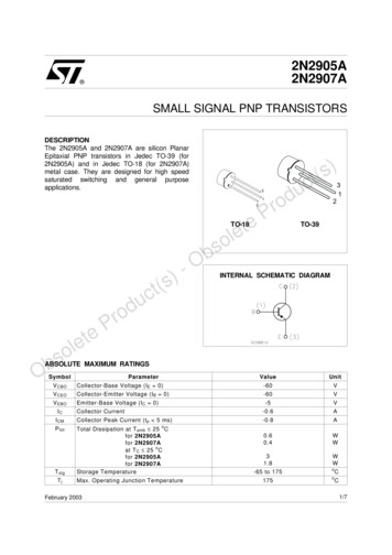
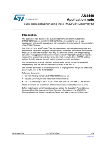
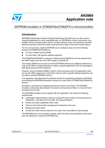
Implementing EEPROM emulationAN39692Implementing EEPROM emulation2.1PrincipleEEPROM emulation is performed in various ways, taking into consideration the Flashmemory limitations and product requirements. The approach detailed below requires atleast two Flash memory sectors of identical size allocated to non-volatile data: one that isinitially erased, and offers byte-by-byte programmability; the other that is ready to take overwhen the former sector needs to be garbage-collected. A header field that occupies the firsthalf word (16-bit) of each sector indicates the sector status. Each of these sectors isconsidered as a page, and called Page0 and Page1 in the rest of this document.The header field is located at the base address of each page and provides the page statusinformation.Each page has three possible states: ERASED: the page is empty. RECEIVE DATA: the page is receiving data from the other full page. VALID PAGE: the page contains valid data and this state does not change until allvalid data is completely transferred to the erased page.Figure 1 shows how the page status changes.Figure 1.Header status switching between page0 and page10AGE 6ALID0AGE %RASED0AGE 0AGE 6ALID0AGE 0AGE %RASED0AGE &ULL2ECEIVE%RASE2ECEIVE0AGE 7RITE 0AGE DATA6ALID&ULL6ALID%RASE#OPY 0AGE DATA 0AGE 0AGE 0AGE 0AGE 7RITE 0AGE DATA#OPY 0AGE DATA 0AGE 0AGE AI 8/22Doc ID 022108 Rev 1
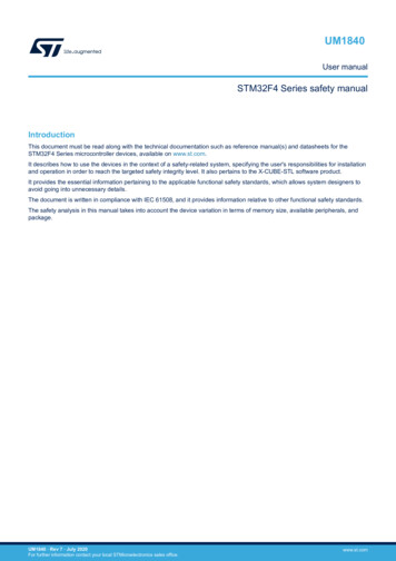
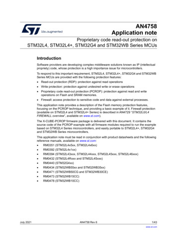
AN3969Table 2.Implementing EEPROM emulationEmulated pages possible status and corresponding actionsPage0Page1ERASEDRECEIVE DATAVALID PAGEERASEDInvalid stateAction: Erase both pagesand format page0Action: Erase Page1 andmark Page0 as VALID PAGERECEIVE DATAAction: Erase Page0 andmark Page1 asVALID PAGEAction: Use page0 as the validInvalid statepage & transfer the last updatedAction: Erase both pages and variables from page0 to page1& mark page1 as valid & eraseformat page0page0VALID PAGEAction: Use page1 as thevalid page & transfer the lastAction: Use page1 as theupdated variables from page1valid page and erase page0to page0 & mark page0 asvalid & erase page1Action: Use page0 as the validpage and erase page1Invalid stateAction: Erase both pages andformat page0Generally, when using this method, the user does not know the variable update frequency inadvance.The software and implementation described in this document use two Flash memorysectors of 16 Kbytes (sector 2 and sector 3) to emulate EEPROM.Note:The choice of sectors 2 and 3 is due to the small size of these sectors compared with theother sectors of the STM32F40x/STM32F41x Flash memory (the main memory block in theSTM32F40x/STM32F41x Flash memory is divided as described in Table 3:STM32F40x/STM32F41x Flash memory sectors). Large sectors can be used, depending onapplication and user needs.Table 3.STM32F40x/STM32F41x Flash memory sectorsNameSector SizeSectors 0 to 316 KbyteSector 464 KbyteSectors 5 to 11128 KbyteEach variable element is defined by a virtual address and a value to be stored in Flashmemory for subsequent retrieval or update (in the implemented software both virtualaddress and data are 16 bits long). When data is modified, the modified data associatedwith the earlier virtual address is stored into a new Flash memory location. Data retrievalreturns the up to date data value.Doc ID 022108 Rev 19/22
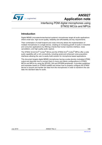
Implementing EEPROM emulationFigure 2.AN3969EEPROM variable format%%02/- VARIABLE ELEMENT BIT WORD6ARIABLE DATA BITS6ARIABLE VIRTUALADDRESS BITS ELEMENTS BYTE SECTORPAGE 3ECTOR PAGE 3ECTOR -3 6 2.2Case of use: application exampleThe following example shows the software management of three EEPROM variables (Var1,Var2 and Var3) with the following virtual addresses:10/22Var1 virtual address5555hVar2 virtual address6666hVar3 virtual address7777hDoc ID 022108 Rev 1
AN3969Implementing EEPROM emulationFigure 3.Data update flow0AGE && &&&& &&&& &&&& &&0AGE && &&&& &&&& &&&& &&&&&&&&&&&&&&&&&&&&&&&&&&&&&&&&&&!DD 6AR H&& && && &&!CTIVE 0AGE 0AGE 0AGE 0AGE && && &&&&&&&&&&&&&&&&&&&&&&&&&& &&&&&&&&&&&&&&&&&&&&&&&&&&0AGE !DD 6AR H && &&0AGE && &&&& &&&& &&&& &&&& &&&& &&&& &&&& &&&& &&&& &&&& &&!DD 6AR "#"#H && &&0AGE && &&&& &&&& &&&& &&&& &&&& &&&& &&&& &&&& &&&& && && &&!CTIVE 0AGE 0AGE && && && &&!CTIVE 0AGE 0AGE && && && &&!CTIVE 0AGE 0AGE 0AGE "# "#!DD VAR H0AGE "# "# 0AGE && &&&& &&&& &&&& &&&& &&&& &&&& && && &&&& && && &&!CTIVE 0AGE 0AGE 0AGE 0AGE && &&&& &&&& &&&& &&&& &&&& &&&& &&&& && " " && &&!CTIVE 0AGE 0AGE 0AGE !DD 6AR H0AGE " " && &&&& && " " && &&!CTIVE 0AGE 0AGE 0AGE && &&&& &&%RASE0AGE &&&&&&&&&&&&&&&&&&&&&&&&&&&&0AGE " " && &&&& &&&& && && &&!CTIVE 0AGE 0AGE AI 2.3EEPROM emulation software descriptionThis section describes the driver implemented for EEPROM emulation using theSTM32F40x/STM32F41x Flash memory driver provided by STMicroelectronics.A sample demonstration program is also supplied to demonstrate and test the EEPROMemulation driver using the three variables Var1, Var2 and Var3 defined in theVirtAddVarTab[] table declared in the software main.c file.The project contains three source files in addition to the Flash memory library source files: eeprom.c: contains the EEPROM emulation firmware functions:EE Init()EE Format()EE FindValidPage()EE VerifyPageFullWriteVariable()EE ReadVariable()EE PageTransfer()EE WriteVariable()eeprom.h: contains the functions prototypes and some declarations. You can use thisfile to adapt the following parameters to your application requirements:–Flash sectors to be used (default: sector 2 and Sector 3)–The device voltage range (default: range 4, 2.7V to 3.6V).In the EEPROM emulation firmware, the FLASH ProgramHalfWord() function isused to program the memory. This function can only be used when the deviceDoc ID 022108 Rev 111/22
Implementing EEPROM emulationAN3969voltage is in the 2.1V to 3.6V range. As consequence, if the device voltage rangeis 1.8V to 2.1 V in your application, you have to use the FLASH ProgramByte()function instead, and adapt the firmware accordingly.– Number of data variables to be used (default: 3)main.c: this application program is an example using the described routines in order towrite to and read from the EEPROM.User API definitionThe set of functions contained in the eeprom.c file, that are used for EEPROM emulation,are described in the table below:Table 4.API definitionFunction nameDescriptionEE Init()Sector header corruption is possible in the event of power loss during data updateor sector erase / transfer. In this case, the EE Init() function will attempt torestore the emulated EEPROM to a known good state. This function should becalled prior to accessing the emulated EEPROM after each power-down. It acceptsno parameters. The process is described in Table 2: Emulated pages possiblestatus and corresponding actions on page 9.EE Format()This function erases page0 and page1 and writes a VALID PAGE header topage0.EE FindValidPage()This function reads both page headers and returns the valid page number. Thepassed parameter indicates if the valid page is sought for a write or read operation(READ FROM VALID PAGE or WRITE IN VALID PAGE).It implements the write process that must either update or create the first instanceof a variable. It consists in finding the first empty location on the active page,starting from the end, and filling it with the passed virtual address and data of thevariable. In the case the active page is full, the PAGE FULL value is returned. Thisroutine uses the parameters below:EE VerifyPageFullWriteVirtual address: may be any of the three declared variables’ virtual addressesVariable()(Var1, Var2 or Var3)Data: the value of the variable to be storedThis function returns FLASH COMPLETE on success, PAGE FULL if there is notenough memory for a variable update, or a Flash memory error code to indicateoperation failure (erase or program).EE ReadVariable()12/22This function returns the data corresponding to the virtual address passed as aparameter. Only the last update is read. The function enters in a loop in which itreads the variable entries until the last one. If no occurrence of the variable isfound, the ReadStatus variable is returned with the value “1”, otherwise it is resetto indicate that the variable has been found and the variable value is returned onthe Read data variable.Doc ID 022108 Rev 1
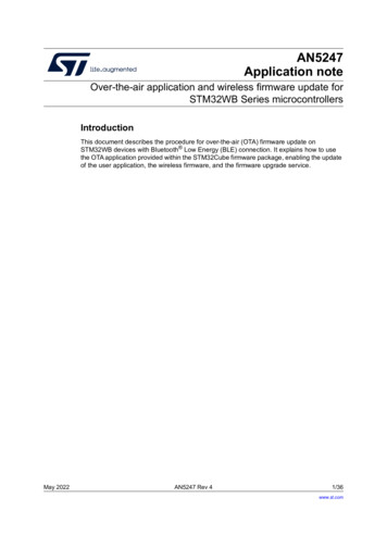
AN3969Table 4.Implementing EEPROM emulationAPI definition (continued)Function nameDescriptionEE PageTransfer()It transfers the latest value of all variables (data with associated virtual address)from the current page to the new active page. At the beginning, it determines theactive page, which is the page the data is to be transferred from. The new pageheader field is defined and written (new page status is RECEIVE DATA given thatit is in the process of receiving data). When the data transfer is complete, the newpage header is VALID PAGE, the old page is erased and its header becomesERASED.EE WriteVariable()This function is called by the user application to update a variable. It uses theEE VerifyPageFullWriteVariable(), and EE PageTransfer() routinesthat have already been described.Note:The following functions can be used to access the emulated EEPROM:- EE Init()- EE ReadVariable()- EE WriteVariable()These functions are used in the application code delivered with this application note.Figure 4 shows the procedure for updating a variable entry in the EEPROM.Figure 4.WriteVariable flowchart&UNCTION CALL!DD ELEMENT REQUEST&IND 6ALID PAGE%%?6ERIFY0AGE&ULL7RITE6ARIABLE %%?&IND6ALID0AGE 9ES%%?0AGE4RANSFER %%?2EAD6ARIABLE #OPY ALL CURRENT ELEMENTS BYREADING THE ACTIVE PAGEFROM THE BOTTOM TAKINGINTO ACCOUNT THE NEWUPDATED ELEMENT CURRENTACTIVE PAGEFULL.O!DD NEW ELEMENT ATTHE ST EMPTY ELEMENTPLACE IN THE CURRENTACTIVE PAGE%RASE PREVIOUS ACTIVE PAGE%ND#HANGE THE ACTIVE PAGE%NDAI BKey features User-configured emulated EEPROM size Increased Flash memory endurance: page erased only when it is full Non-volatile data variables can be updated infrequently Interrupt servicing during program/erase is possibleDoc ID 022108 Rev 113/22
Implementing EEPROM emulation2.4AN3969EEPROM emulation memory footprintTable 5 details the footprint of the EEPROM emulation driver in terms of Flash size and RAMsize.The table and figure below have been determined using the IAR EWARM 6.10 tool with HighSize optimization level.Table 5.Memory footprint for EEPROM emulation mechanismMinimum(1) required code size (bytes)MechanismEEPROM emulation software mechanismFlashSRAM98461. Based on one 32-bit variable (16-bit for address and 16-bit for data). The SRAM memory used increasesdepending on the number of variables used.Figure 5.Flash memory footprint for EEPROM emulation (mechanism and storage)&LASH -EMORY BYTE BYTE BYTE BYTE BYTE3ECTOR 3ECTOR 3ECTOR 3ECTOR 3ECTOR BYTE3ECTOR BYTE3ECTOR 3ECTOR ,ESS THAN BYTE OF BLOCK,ESS THAN BYTE USED BYTE 3ECTOR &LASH USED TO IMPLEMENT THE %%02/- EMULATION MECHANISM&LASH USED FOR %%02/- DATA STORAGE&LASH NOT USED-3 6 14/22Doc ID 022108 Rev 1
AN39692.5Implementing EEPROM emulationEEPROM emulation timingThis section describes the timing parameters associated with the EEPROM emulation driverbased on two 16 Kbyte EEPROM page sizes.All timing measurements are performed: STM32F407IGT6 Revision A With the voltage range 3 (2.7 V to 3.6 V) System clock at 168 MHz, Flash prefetch disabled and cache features enabled With execution from Flash At room temperatureTable 6 lists the timing values for EEPROM.Table 6.EEPROM emulation timings with a 168 MHz system clockEEPROM emulation timingsOperationTypical (1) variable(2) Write operation in EEPROMVariable Write operation with page swap(3)in EEPROMVariable Read Operation from EEPROM (4)EEPROM Initialization for the 1st timeTypical EEPROM InitializationMinimumTypicalMaximum28 µs-255 µs-237 ms0.68 µs-(5)(6)251 µs473 ms237 ms1. Write with no page swap. The minimum value refers to a write operation of a variable in the beginning ofthe Flash sector and the maximum value refers to a write operation in the end of the Flash sector. Thedifference between the minimum and maximum values is due to the time taken to find a free Flash addressto store the new data.2. Variable size used is 32-bit (16-bit for the virtual address and 16-bit for the data)3. Page swapping is done when the valid page is full. It consists of transferring the last stored data for eachvariable to the other free page and erasing the full page.4. The minimum value refers to a read operation of the 1st variable stored in the Flash sector and themaximum value refers to a read operation of the last variable -1. The difference between the minimum andmaximum values is due to the time taken to find last stored variable data.5. When the EEPROM mechanism is run for the 1st time or for invalid status (refer to Table 2: Emulatedpages possible status and corresponding actions on page 9 for more detail), the two pages are erased andthe page used for storage is marked as VALID PAGE.6. A typical EEPROM initialization is performed when a valid page exists (the EEPROM has been initialized atleast once). During a typical EEPROM initialization, one of the two pages is erased (see Table 2: Emulatedpages possible status and corresponding actions on page 9 for more detail).Doc ID 022108 Rev 115/22
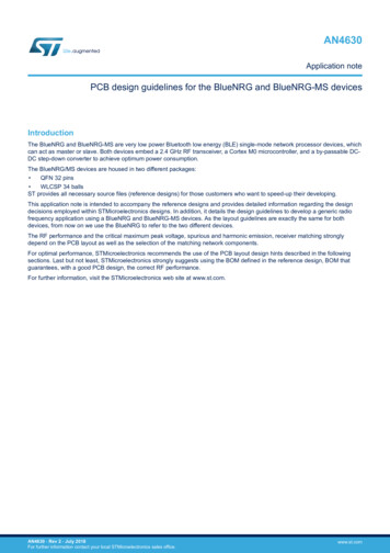
Embedded application aspects3AN3969Embedded application aspectsThis section provides advice on how to overcome software limitations in embeddedapplications and how to fulfill the needs of different applications.3.1Data granularity managementEmulated EEPROM can be used in embedded applications where non-volatile storage ofdata updated with a byte, half-word or word granularity is required. It generally depends onthe user requirements and Flash memory architecture (for example, stored data length,write access).The STM32F40x/STM32F41x on-chip Flash memory allows 8-bit, 16-bit or wordprogramming depending on the voltage range used as described in Table 7.Table 7.Flash program functionsData granularityFunction nameFunctional Voltage rangeby Word(32-bit)FLASH ProgramWordFrom 2.7 V to 3.6 V.by half word(16-bit)FLASH ProgramHalfWordFrom 2.1 V to 3.6 V.FLASH ProgramByteAll the device supply voltage ranges.by byte(8-bit)(1)1. Programming on a byte-by-byte basis: writing by byte offers the possibility of storing more data variables.The performance may however be reduced when using the FLASH ProgramByte() function. Werecommend that you use the FLASH ProgramHalfWord() function. Both virtual address and data can bewritten simultaneously as a half word.3.2Wear leveling: Flash memory endurance improvementIn the STM32F40x/STM32F41x on-chip Flash memory, each sector can be programmed orerased reliably around 10 000 times.For write-intensive applications that use more than two pages (3 or 4) for the emulatedEEPROM, it is recommended to implement a wear-leveling algorithm to monitor anddistribute the number of write cycles among the pages.When no wear-leveling algorithm is used, the pages are not used at the same rate. Pageswith long-lived data do not endure as many write cycles as pages that contain frequentlyupdated data. The wear-leveling algorithm ensures that equal use is made of all theavailable write cycles for each sector.Note:The main memory block in the STM32F40x/STM32F41x Flash memory is divided asdescribed in Table 3: STM32F40x/STM32F41x Flash memory sectors.3.2.1Wear-leveling implementation exampleIn this example, in order to enhance the emulated EEPROM capacity, four sectors will beused (sector5 as Page0, sector6 as Page1, sector7 as Page2 and sector8 as Page3).The wear-leveling algorithm is implemented as follows: when page n is full, the deviceswitches to page n 1. Page n is garbage-collected and then erased. When it is the turn ofPage3 to be full, the device goes back to Page0, Page3 is garbage-collected then erasedand so on (refer to Figure 6).16/22Doc ID 022108 Rev 1
AN3969Embedded application aspectsFigure 6.Page swap scheme with four pages (wear leveling)0AGE 0AGE 0AGE 0AGE &&&&&&&&&&&& &&&&&&&&&&&&&&&&&&&&&&&&!CTIVE 0AGE%RASED%RASED%RASEDAI In the software, the wear-leveling algorithm can be implemented using theEE FindValidPage() function (refer to Table 4).3.3Page header recovery in case of power lossData or page header corruption is possible in case of a power loss during a variable update,page erase or transfer.To detect this corruption and recover from it, the EE Init() routine is implemented. Itshould be called immediately after power-up. The principle of the routine is described in thisapplication note. The routine uses the page status to check for integrity and perform repair ifnecessary.After power loss, the EE Init() routine is used to check the page header status. Thereare 9 possible status combinations, three of which are invalid. Table 2: Emulated pagespossible status and corresponding actions on page 9 shows the actions that should betaken based on the page statuses upon power-up.3.4Cycling capability and page allocation3.4.1Cycling capabilityA program/erase cycle consists of one or more write accesses and one page eraseoperation.When the EEPROM technology is used, each byte can be programmed and erased a finitenumber of times, typically in the range of 10 000 to 100 000.Doc ID 022108 Rev 117/22
Embedded application aspectsAN3969However, in embedded Flash memory, the minimum erase size is the sector and the numberof program/erase cycles applied to a sector is the number of possible erase cycles. TheSTM32F40x/STM32F41x’s electrical characteristics guarantee 10 000 program/erasecycles per sector. The maximum lifetime of the emulated EEPROM is thereby limited by theupdate rate of the most frequently written parameter.The cycling capability depends on the amount/size of data that the user wants to handle.In this example, two sectors (of 16 Kbytes) are used and programmed with 16-bit data. Eachvariable corresponds with a 16-bit virtual address. That is, each variable occupies a word ofstorage space. A sector can store 16 Kbytes multiplied by the Flash memory endurance of10 000 cycles, giving a total of 160 000 Kbytes of data storage capacity for the lifetime ofone page in the emulated EEPROM memory. Consequently, 320 000 Kbytes can be storedin the emulated EEPROM, provided t
example) should be considered when designing the Flash memory management software. To design robust Flash memory management software a thorough understanding of the Flash memory erase process is necessary. Note: In the case of a CPU reset, ongoing sector erase or mass erase operations on the STM32F40x/STM32F41x embedded Flash are not interrupted.