Transcription
AN4449Application noteBuck-boost converter using the STM32F334 Discovery kitIntroductionThis application note describes the buck-boost DC/DC converter included in theSTM32F334 Discovery kit (32F3348DISCOVERY), a low-cost and easy-to-usedevelopment kit to quickly evaluate and start application development with microcontrollersof the STM32F3 series.The STM32F334xx ARM Cortex -M4 microcontrollers, combining high integration andperformance, have been designed for digital power conversion applications and this buckboost DC/DC converter illustrates how they can efficiently control an H-bridge topologyconverter. This application note demonstrates how the STM32F334xx products meet theneeds of this function thanks to their embedded high-resolution timer (HRTIM) and thesettings flexibility adapted for such switching-based converter application.This demonstration example needs an external power supply that will be connectedindependently from the mini-B USB cable connected to the host PC.The firmware associated to this example needs to be programmed into your STM32F334Discovery kit prior to the demonstration.Reference documents: UM1733: Getting started with STM32F334 Discovery kit; DB2343: Discovery kit for STM32F334 microcontrollers; UM1735: Discovery kit for STM32F3 series with STM32F334C8 MCU User Manual.These documents are available on STMicroelectronics web site (http://www.st.com).Before installing and using the product, please accept the Evaluation Product LicenseAgreement from http://www.st.com/epla. For more information on the STM32F334Discovery board and for demonstration software, visit www.st.com/stm32f3discovery.September 2014DocID025970 Rev 11/34www.st.com1
ContentsAN4449Contents12Application description . . . . . . . . . . . . . . . . . . . . . . . . . . . . . . . . . . . . . . 51.1Required hardware . . . . . . . . . . . . . . . . . . . . . . . . . . . . . . . . . . . . . . . . . . . 51.2Hardware settings of the STM32F334 Discovery kit . . . . . . . . . . . . . . . . . 51.3Application schematics . . . . . . . . . . . . . . . . . . . . . . . . . . . . . . . . . . . . . . . . 61.4Application principles . . . . . . . . . . . . . . . . . . . . . . . . . . . . . . . . . . . . . . . . . 61.4.1Overview . . . . . . . . . . . . . . . . . . . . . . . . . . . . . . . . . . . . . . . . . . . . . . . . . 61.4.2Non-inverting buck/boost converter basics . . . . . . . . . . . . . . . . . . . . . . . 81.4.3Sizing the inductor of the buck-boost converter . . . . . . . . . . . . . . . . . . . 141.4.4Setting the STM32F334 High-resolution timer . . . . . . . . . . . . . . . . . . . . 141.4.5Software overload protection . . . . . . . . . . . . . . . . . . . . . . . . . . . . . . . . . 161.4.6PI software regulation . . . . . . . . . . . . . . . . . . . . . . . . . . . . . . . . . . . . . . 221.4.7Getting started with the application . . . . . . . . . . . . . . . . . . . . . . . . . . . . 23Firmware description . . . . . . . . . . . . . . . . . . . . . . . . . . . . . . . . . . . . . . . 262.1STM32F334xx peripherals used by the application . . . . . . . . . . . . . . . . . 262.1.12.2Setting #define constants . . . . . . . . . . . . . . . . . . . . . . . . . . . . . . . . . . . . 27Application flowcharts description . . . . . . . . . . . . . . . . . . . . . . . . . . . . . . 282.2.1Application “main.c” flowchart . . . . . . . . . . . . . . . . . . . . . . . . . . . . . . . . 282.2.2Application “HRTIM1 TIMA IRQHandler()” flowchart . . . . . . . . . . . . . . 293DC/DC converter main electrical characteristics . . . . . . . . . . . . . . . . . 314Conclusions . . . . . . . . . . . . . . . . . . . . . . . . . . . . . . . . . . . . . . . . . . . . . . . 325Revision history . . . . . . . . . . . . . . . . . . . . . . . . . . . . . . . . . . . . . . . . . . . 332/34DocID025970 Rev 1
AN4449List of tablesList of tablesTable 1.Table 2.Table 3.Table 4.Table 5.Table 6.Table 7.HRTIM output signals through operating modes . . . . . . . . . . . . . . . . . . . . . . . . . . . . . . . . 15Event settings through operating modes . . . . . . . . . . . . . . . . . . . . . . . . . . . . . . . . . . . . . . 15Collection table for buck mode . . . . . . . . . . . . . . . . . . . . . . . . . . . . . . . . . . . . . . . . . . . . . . 18Collection table for boost mode . . . . . . . . . . . . . . . . . . . . . . . . . . . . . . . . . . . . . . . . . . . . . 18Collection table for mixed mode . . . . . . . . . . . . . . . . . . . . . . . . . . . . . . . . . . . . . . . . . . . . . 19Main electrical characteristics . . . . . . . . . . . . . . . . . . . . . . . . . . . . . . . . . . . . . . . . . . . . . . . 31Document revision history . . . . . . . . . . . . . . . . . . . . . . . . . . . . . . . . . . . . . . . . . . . . . . . . . 33DocID025970 Rev 13/343
List of figuresAN4449List of figuresFigure 1.Figure 2.Figure 3.Figure 4.Figure 5.Figure 6.Figure 7.Figure 8.Figure 9.Figure 10.Figure 11.Figure 12.Figure 13.Figure 14.Figure 15.Figure 16.Figure 17.Figure 18.Figure 19.Figure 20.Figure 21.Figure 22.4/34Connecting the external power supply . . . . . . . . . . . . . . . . . . . . . . . . . . . . . . . . . . . . . . . . . 5Overview of STM32F334 Discovery kit. . . . . . . . . . . . . . . . . . . . . . . . . . . . . . . . . . . . . . . . . 6STM32F334 Discovery Buck/Boost converter topology . . . . . . . . . . . . . . . . . . . . . . . . . . . . 7Step-down operation (buck mode) . . . . . . . . . . . . . . . . . . . . . . . . . . . . . . . . . . . . . . . . . . . . 8Step-down operation signals (buck mode) . . . . . . . . . . . . . . . . . . . . . . . . . . . . . . . . . . . . . . 8Step-up operation (boost mode) . . . . . . . . . . . . . . . . . . . . . . . . . . . . . . . . . . . . . . . . . . . . . 10Step-up operation signals (boost mode) . . . . . . . . . . . . . . . . . . . . . . . . . . . . . . . . . . . . . . . 10Buck-boost operation (mixed mode) . . . . . . . . . . . . . . . . . . . . . . . . . . . . . . . . . . . . . . . . . . 11Buck-boost cascaded transfer functions . . . . . . . . . . . . . . . . . . . . . . . . . . . . . . . . . . . . . . . 12Operating modes according to VIN level . . . . . . . . . . . . . . . . . . . . . . . . . . . . . . . . . . . . . . . 12Buck-boost operation signals (mixed mode). . . . . . . . . . . . . . . . . . . . . . . . . . . . . . . . . . . . 13ADC trigger event configuration in buck and boost modes. . . . . . . . . . . . . . . . . . . . . . . . . 16DC/DC converter characterization . . . . . . . . . . . . . . . . . . . . . . . . . . . . . . . . . . . . . . . . . . . 17Duty cycle value vs. VIN for a given VOUT in buck mode . . . . . . . . . . . . . . . . . . . . . . . . . . 19Duty cycle value vs. VIN for a given VOUT in boost mode . . . . . . . . . . . . . . . . . . . . . . . . . . 20Duty cycle value vs. VIN for a given VOUT in mixed mode . . . . . . . . . . . . . . . . . . . . . . . . . 20PI software controller . . . . . . . . . . . . . . . . . . . . . . . . . . . . . . . . . . . . . . . . . . . . . . . . . . . . . 22Signal LEDs during standard operation . . . . . . . . . . . . . . . . . . . . . . . . . . . . . . . . . . . . . . . 24Signal LEDs during limited operation . . . . . . . . . . . . . . . . . . . . . . . . . . . . . . . . . . . . . . . . . 24Signal LEDs during fault condition . . . . . . . . . . . . . . . . . . . . . . . . . . . . . . . . . . . . . . . . . . . 25“main.c” flowchart . . . . . . . . . . . . . . . . . . . . . . . . . . . . . . . . . . . . . . . . . . . . . . . . . . . . . . . . 28“HRTIM1 TIMA IRQHandler()” flowchart. . . . . . . . . . . . . . . . . . . . . . . . . . . . . . . . . . . . . . 29DocID025970 Rev 1
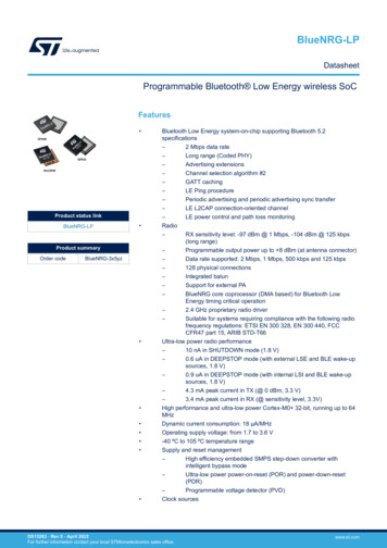
AN4449Application description1Application description1.1Required hardwareThis application uses STM32F334 Discovery kit on-board buck-boost DC/DC converter and4 signal LEDs (LD3 to LD6). An external DC power supply (0-15 VDC 1 A max.) is requiredfor the demonstration.The external power supply will be connected to CN5 (VIN) connector, while the VOUT signalwill be present on CN7.The user will manage externally the current limitation to approximately 500 mA even if aninternal protection against overload is included in this firmware demonstration.Caution:Please comply with VIN polarity when connecting the power supply as well for VOUT whenconnecting an external load or metering tools, as shown in Figure 1.Figure 1. Connecting the external power supply&ZKD yd ZE WKt Z hWW zs/EsKhdн Eϲ'E Eϱ ϯн'E Eϳ h ͬ KK d ͬ KEs Zd Z06 9 Note:This example and its hardware are totally independent from high brightness LED featuresdescribed in other documents.1.2Hardware settings of the STM32F334 Discovery kitThe SBx solder bridges should be set in their initial factory configuration. The user willpossibly connect an external current probe on CN6 pads to observe the inductor (L3)current during operation. In that case, SB22 must be removed on the board bottom side.Refer to STM32F334 Discovery kit user manual (UM1735) for further information related tohardware.DocID025970 Rev 15/3433
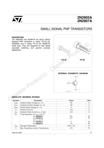
Application description1.3AN4449Application schematicsFigure 2 shows the description of STM32F334 Discovery kit hardware.Figure 2. Overview of STM32F334 Discovery kit dͲ /E WƵƐŚͲďƵƚƚŽŶƐ ϭhƐĞƌ dDϯϮ&ϯϯϰϴ ZD ŽƌƚĞdž Dϰ Ϯ ŝŐŶĂů ƐZĞƐĞƚ/E ƵĐŬͬ ŽŽƐƚ ͬ ŽŶǀĞƌƚĞƌKhd,ŝŐŚ ďƌŝŐŚƚŶĞƐƐ 06 9 1.4Application principles1.4.1OverviewThe STM32F334 Discovery embeds a buck-boost DC/DC converter that allows efficientconversion of a DC voltage from one level to another.The user can apply an input DC voltage from a range of 3 to 15 V maximum and use theconverter to get this voltage converted into a DC voltage ranging from 3 to 15 V maximum.The VOUT target is set prior with a target constant defined into the firmware.Due to the inductor size and the input/output varying conditions, the allowed output currentis given for 0.5 A typical. The input voltage can be converted to a lower voltage level using astep-down mode, or converted to a higher level using a step-up mode. These 2 modes aresupported with a single H-bridge converter using a non-inverting buck-boost topology.The STM32F334 microcontroller is interfaced to the power switches with a minimumhardware, some acting as level shifters especially to adapt the low-level voltage ofmicrocontroller supply to the power stages connected to the external source. The buckboost converter topology is sketched in Figure 3.6/34DocID025970 Rev 1
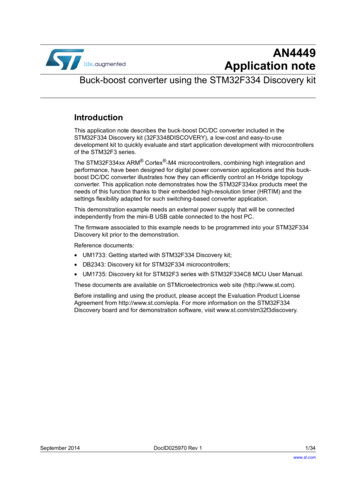
AN4449Application descriptionFigure 3. STM32F334 Discovery Buck/Boost converter topology s/EW,Ͳ dW s ,/&d ZE s ,/&d ZEd Ϯd ϭ E d ϭ,ŝŐŚͲƌĞƐŽůƵƚŝŽŶ d/D Z d Ϯ E 06 9 As shown above, the high-resolution timer controls the N and P MOS switches of H-bridgeconverter. The P-MOSFETs are not directly connected to the high-resolution timer butinterfaced with level shifters, while the logic level N-MOSFETs are directly controlled by theMCU. These level shifters are made up of a bipolar totem-pole driver. Please refer toUM1735 for further details on converter schematics.The buck-leg (left side of H-bridge) is driven by TA1 (for the PMOS) and TA2 (for the NMOS)signals from HRTIM (high-resolution timer) and the boost-leg (right side of H-bridge) isdriven by TB1 (for the NMOS) and TB2 (for the PMOS) signals from HRTIM. This converterstructure uses 4 MOSFET switches to allow synchronous rectification that improvesconverter efficiency and thermal performance. This consists to replace the rectificationdiodes commonly used in buck or boost converter stages by MOSFET transistors ensuringthe current rectification and providing better efficiency in low-output-voltage and highcurrent power supplies. The conduction losses in the freewheeling diodes can represent asignificant part of the power losses of switching converters.The internal HRTIM PWM switching frequency is 250 kHz. Both VIN and VOUT signals aresensed by the ADC peripheral and the varying error vs. the VOUT target is evaluated.This mode is called voltage mode control as the output regulation is based on voltagemeasurement. The PWM duty is then computed internally by a proportional integralcontroller (PI) based on ADC inputs.The input or output currents are not sensed by any hardware current sensing method(series sense resistor, MOSFET current sensing, current transformers, etc.) but evaluatedby a software solution described later in this document.Caution:For safety reasons, users must not modify the current design and must comply withfirmware operating limitations. Moreover, USB voltage source is not recommended as analternate power supply source for VIN as this can damage the board or the host USB PCport if a high current is forced in the converter.DocID025970 Rev 17/3433
Application description1.4.2AN4449Non-inverting buck/boost converter basicsStep-down operation (buck mode)This mode operates when VIN VOUT target and when the converter lowers the inputvoltage level.As shown in Figure 4, TA1 and TA2 are two PWM signals generated by the HRTIM and acttogether as complementary signals. As evidenced by the converter topology, two transistorsfrom a same leg cannot be switched at the same time (thus risking to create a short-circuiton the power line). Therefore Q1 and Q2 cannot be turned ON together and must bemanaged one by one with the HRTIM peripheral by inserting dead-time periods betweenconductions of Q1 and Q2 as shown in Figure 5. When Q1 is closed, the inductor chargephase is observed. When Q2 is closed at its turn, the inductor discharge phase can start. Onthe right side of the H-bridge, Q4 is maintained closed and Q3 open during all buckoperating phase.Note:In figures 4 and 5 the same color scheme has been used to indicate current flows.Figure 4. Step-down operation (buck mode)/ĐŚĂƌŐĞ sKhds/Ed ϭ YϰYϭ d ϮYϮ/ĚŝƐĐŚĂƌŐĞYϯ06 9 Figure 5. Step-down operation signals (buck mode)ĚĞĂĚͲƚŝŵĞĚĞĂĚͲƚŝŵĞƚWtDd ϭƚKEƚK&&ƚYϭ KEYϭ K&&YϮ K&&YϮ KEd Ϯƚ/ /ŽƵƚŵĂdž/ƌŝƉƉůĞŵŝŶƚ06 9 8/34DocID025970 Rev 1
AN4449Application descriptionDuring charge phase, Q1 is closed and the VIN voltage is applied to the inductor. Thecurrent flows through the inductor and the output capacitor is charged through the ground. Ifthe voltage across Q1 and Q4 are ignored (ideal switches), the relation between VIN, VOUT,L and the current IL flowing through L can be expressed by the formula below:Vin Vout LdiLdtDuring discharge phase, Q1 is open and the current continues to flow through Q2 (nowclosed) and through the inductor. In this condition and with Q2 and Q4 drop voltagesignored as well, the formula between the current, L and VOUT becomes: Vout LdiLdtIf the HRTIM PWM switching period is TPWM (in seconds) then the charge phase tON andthe discharge phase tOFF are linked together by the formula:tON tOFF TPWMThe PWM duty cycle is the ratio of time when Q1 is turned ON over the total TPWM period. Dis always included between 0 and 1. It can be expressed as:D tONTPWMWhen Q1 is turned OFF, the OFF time is equivalent to:tOFF (1 D) TPWMConsidering that the average voltage across the inductor L is zero during a whole PWMperiod and to prevent any saturation into the coil, the relation between VIN and VOUT for thestep-down converter (buck mode) is:D (Vin Vout ) (1 D) ( Vout ) 0D Vin D Vout Vout D Vout 0This sums up to:Vout DVinStep-up operation (boost mode)This mode operates when VIN VOUT target and when the converter raises the inputvoltage level. As shown in Figure 6, TB1 and TB2 are two PWM signals generated by theHRTIM and are working together as complementary signals. As it was the case in the buckmode, and for the same H-bridge leg, Q3 and Q4 cannot be turned ON at the same time, asshown in Figure 7. When Q3 is closed, the inductor charge phase takes place. When Q4 isclosed, the inductor discharge phase starts. On the left side of the H-bridge, Q1 ismaintained closed and Q2 open during all boost operating phase.DocID025970 Rev 19/3433
Application descriptionNote:AN4449In figures 6 and 7 the same color scheme has been used to indicate current flows.Figure 6. Step-up operation (boost mode)/ĚŝƐĐŚĂƌŐĞ sKhds/EYϭYϰ d Ϯ /ĐŚĂƌŐĞYϮYϯd ϭ06 9 Figure 7. Step-up operation signals (boost mode)ĚĞĂĚͲƚŝŵĞĚĞĂĚͲƚŝŵĞƚWtDd ϭƚKEƚK&&ƚYϯ KEYϯ K&&Yϰ K&&Yϰ KEd Ϯƚ/ /ŽƵƚŵĂdž/ƌŝƉƉůĞŵŝŶƚ06 9 During charge phase, Q3 is closed and the VIN voltage is applied on the inductor throughthe ground. If the voltages across Q1 and Q3 are ignored (ideal switches), the relationbetween VIN, L and the current IL flowing through L can be expressed by the formula below:Vin LdiLdtDuring discharge phase, Q3 is open and the current continues to flow through the inductorand Q4 (now closed) and finally through the output capacitor. In this condition and with Q1and Q4 drop voltages ignored as well, the formula between VIN, the current IL, L and VOUTbecomes:Vin Vout L10/34DocID025970 Rev 1diLdt
AN4449Application descriptionFor the charge phase tON and the discharge phase tOFF the same formula can be applied:tON tOFF TPWMThe PWM duty cycle is the ratio of time when Q3 is turned ON over the total TPWM period. Itcan be expressed with D always included between 0 and 1as:D tONTPWMWhen Q3 is turned OFF, the OFF time is equivalent to:tOFF (1 D) TPWMFor the boost mode, the following formula can be applied:D Vin (1 D) (Vin Vout) 0D Vin Vin Vout D Vin D Vout 0Vin Vout (1 D)That finally gives:Vout1 Vin 1 DBuck-boost operation (mixed mode)This mode occurs when VIN is near VOUT (VIN VOUT) and none of the buck or boostmodes can independently achieve VOUT target regulation. It uses both buck and boost sidesof the H-bridge converter and the 4 HRTIM outputs TA1, TA2, TB1 and TB2 generate PWMsignals where TA1 and TB1 are still complementary respectively to TA2 and TB2.In this application example, during buck-boost operation, the buck duty cycle is maintainedfixed while the boost duty cycle is variable according to VIN and VOUT conditions.Figure 8. Buck-boost operation (mixed mode) sKhds/Ed ϭ YϰYϭd Ϯ YϮd ϮYϯd ϭ06 9 In the buck-boost mode, both operations are cascaded. Considering the buck mode as atransfer function f1 with D1 as an input parameter and the boost mode as a transfer functionf2 with D2 as an input parameter, the equivalent scheme shown in Figure 9 can be applied:DocID025970 Rev 111/3433
Application descriptionAN4449Figure 9. Buck-boost cascaded transfer functionss/E h ;ĨϭͿ ϭd ϭd ϮsKhd ůŽĂĚ KK d ;ĨϮͿ ϮsϬd ϭd Ϯ06 9 Now applying the consecutive equations for buck and boost converters:V 0 f 1( D1) VinandVout f 2( D 2) V 0then the global transfer function f is:Vout f ( D1, D 2) f 1( D1) f 2( D 2)VinAs the transfer functions based on the converter duty cycles for buck and boost have beenmentioned above in this document, this finally gives for the buck-boost converter mode:1VoutD1 D1 Vin1 D2 1 D2As an example, setting D1 buck duty cycle to 0.8 (fixed), with a variation of D2 boost dutycycle between 0.05 and 0.45, allows to have a VOUT / VIN ratio varying from 0.85 to 1.45,thus covering the entire range of VOUT close to VIN.The purpose is to have 3 operating modes that are slightly overlapped between adjacentranges, as graphically shown in Figure 10.Figure 10. Operating modes according to VIN levels/E h h Ͳ KK d h Ͳ KK ddsKhd KK d06 9 12/34DocID025970 Rev 1
AN4449Application descriptionThis overlap prevents from sporadic switching from one mode to another especially whenthe converter operation is located at the threshold of the maximum or minimum operatingduty for the current mode. It acts like a hysteresis and improves application stability.Consequently, if a VOUT target is set, the converter can operate in the 3 areas, for the casesVIN VOUT, VIN VOUT, or VIN VOUT.Concerning the buck-boost operating signals, the buck operation is achieved with a fixedPWM waveform on TA1 (TA2 as complementary) and the boost one with a variable PWMduty cycle on TB1 (TB2 as complementary) as shown in Figure 11, where the same colorscheme of figures 4 to 7 has been used for currents.In this example, the PWM duty cycle D1 applied on buck side is fixed to 0.8 and the PWMduty cycle D2 applied on the boost side may vary from 0.05 up to 0.45. Theoretically, if VIN VOUT, D1 and D2 should be complementary, as for instance, if D1 is fixed to 0.8, then D2should be 0.2 referring to the relation between VIN, VOUT, D1 and D2 seen above. In realapplication case, D2 needs some margins to introduce more flexibility between theconversion modes and ensure a minimum hysteresis over operating ranges.The IL current waveform can be broken down into 3 regions, as shown in Figure 11.Figure 11. Buck-boost operation signals (mixed mode)The first phase is equivalent to the boost time when phases 2 and 3 correspond to the bucktime. This curve is represented when VIN is very close to VOUT due to the horizontal lineobserved in section 2. If VIN is slightly lower than VOUT, the line slope located in section 2DocID025970 Rev 113/3433
Application descriptionAN4449becomes negative and the current decreases through the inductor during this time slot. Onthe opposite, if VIN is slightly higher than VOUT, the line slope located in section 2 is positiveand the current through the inductor increases for this same time slot.Equations previously defined for buck and boost modes can be applied for the requiredperiod.1.4.3Sizing the inductor of the buck-boost converterObjectives of this buck-boost converter are to have an input voltage range from 3 VDC to15 VDC maximum and the same parameters for the output voltage. For the converter, thetypical output current is 500 mA. The HRTIM switching frequency is selected to have aPWM frequency of 250 kHz. A relevant estimation for the inductor ripple current is 30%typical of the output current value.For the buck mode, with a maximum of 15 VDC in input and a minimum of 3 VDC on theoutput, the value of theoretical duty D is 3/15 0.2.Based on these parameters and from the initial equation:VL LdiLdtThe inductor L estimation value can be calculated with the formula below:L min L min (Vin Vout )1 D FpwmIripple(15 3)1 0.2 64µH2500000.5 0.3For the boost mode, the input and output ranges are similar and the formula is now:L min Vin 2 (Vout Vin)1 2FpwmVoutIrippleThe chosen value is L 82 µH with a resistance rL of 460 mΩ typical, and typical saturationcurrent of 1.1 A.1.4.4Setting the STM32F334 High-resolution timerThis section describes how the STM32F334 high-resolution timer is set for this applicationexample. As described above, the N and P MOSFETs of the H-bridge converter are eachones assigned to one of the HRTIM outputs. For the buck right side, there are TA1 and TA2PWM waveforms connected to the buck-leg and for the boost left side, TB1 and TB2 PWMwaveforms connected to the boost-leg. TA1 and TA2, as well as TB1 and TB2 act ascomplementary signals.There are 4 modes that control the buck boost converter, as described in Table 1.14/34DocID025970 Rev 1
AN4449Application descriptionTable 1. HRTIM output signals through operating modesConverter MB/PWMBIDLE mode is a waiting mode when only timers A and B have been started but none of theoutputs has been set yet.As soon as outputs from Timer A or Timer B are controlled, there is one state configured forthe timer period event and another one configured for a compare event (or a few ones). ThePWM period is selected to 4µs (fPWM 250 kHz). Each 4 µs, the timer period event occurs.Since both timer A and timer B are synchronized together, the period event is common forthe 2 timers. To activate the related outputs to timer A and B, one (or more) compare eventsis (are) created, as shown in Table 2.Table 2. Event settings through operating modesConverter modeALLBUCKMIXEDPeriodCMP1CMP2CMP4CMP1Timer A4 µsDutyA-ADCtriggerDutyATimer B4 er--ADCtrigger-DutyB--Sliding ADC trigger eventSwitching converters generate noise on the power lines due to the fast switch of the powerMOSFETs. Nevertheless, the application has to measure regularly the values of VIN andVOUT voltages during operation and potentially during switching time periods.According to the different operating modes, buck, mixed and boost modes, there are variousswitching events on the timers outputs that can degrade the ADC measure when performedat a regular time without looking at conditions on HRTIM outputs. For instance, if the ADCmeasure is defined at the half of the PWM period while the duty cycle of an HRTIM outputsignal reaches 0.5, both ADC and switching event are performed at the same time. Toensure that the ADC measure is not polluted by the noise during a MOSFET transition, theADC trigger event has to be determined according to the current duty cycle value and alsodepending on the various switching events due to the considered mode.To improve VIN and VOUT ADC measurement accuracy and to carry out the sampling in anon-transition period, the ADC trigger event is adapted every time the duty cycle changes.DocID025970 Rev 115/3433
Application descriptionAN4449There are 2 conditions that are checked before applying the ADC trigger event time:1.Buck or Boost mode operation:In this case, only one group of complementary outputs is active (TAx or TBx). The timevalue of the ADC trigger event depends essentially on the value of the running dutycycle. The ADC trigger time is assigned on the opposite sector of the signal transitionand its event also slides with the value of the duty cycle. It depends upon tON or tOFFvalue, therefore the ADC trigger position varies with duty cycle as shown in Figure 12.2.Mixed (buck-boost) mode operation:In this case, both groups TAx and TBx are active (see Figure 11). As the buck mode isset with a fixed duty cycle of 0.8 and the boost mode duty cycle cannot exceed 0.45,therefore the ADC trigger time event is set to a fixed value corresponding to a freemeasuring window located in between. The value of ADC trigger time is typically 60%of the overall PWM period.Figure 12. ADC trigger event configuration in buck and boost modes ƚƌŝŐŐĞƌ ĞǀĞŶƚ с ƚKE ͬϮddžϭ ƚƌŝŐŐĞƌ ĞǀĞŶƚ с ƚWtD Ͳ ƚK&& ͬϮƚWtDƚKEddžϭƚWtDƚK&&ƚddžϮƚddžϮƚƚ ƵƚLJ ĐLJĐůĞ ф Ϭ͘ϱ ƵƚLJ ĐLJĐůĞ х Ϭ͘ϱ06 9 1.4.5Software overload protectionBuck-boost converters generally use different methods to evaluate the load current sourcedby the converter. There are several means but the most common method is to sense theload current with a current sense resistor inserted serially into the output circuitry. Thisallows controlling the maximum inductor current and to prevent any overload conditions.The drawback is to introduce power losses caused by the inserted resistor and resulting in alower converter efficiency. Even if there are lossless current-sensing methods, here adifferent approach has been used for this application example.As described above in step-up or step-down operations in buck-boost basics chapter, thetheoretical duty cycle is known for a given operating mode (buck, boost, etc.) and can becalculated by the VIN / VOUT ratio applied onto the converter. As for instance, a 10 VDC inputvoltage can be converted into 5 VDC output voltage with a duty cycle equal to 0.5 (buckmode). This basic assumption does not take into account the DC/DC converter efficiency fora given output load current. The relation for buck mode is actually where η is the efficiencyfactor:Vout η DVin16/34DocID025970 Rev 1
AN4449Application descriptionTherefore, the application cannot anticipate itself the approximate value of the outputcurrent based on the running mode and the duty cycle applied during operation.The idea isto have this information available and stored into the microcontroller memory by anticipatingthe efficiency based on the real case operation. For this purpose, the following configurationis set as in Figure 13.Figure 13. DC/DC converter characterization s/E ͬ ĐŽŶǀĞƌƚĞƌ /ŝŶĨϭ; ϭͿĨϮ; ϮͿ sKhd ůŽĂĚ/ŽƵƚ06 9 This DC/DC converter has been designed to have a typical current of 0.5 A for both Iin andIout.The idea is to characterize the application in the different operating modes according tovarious VIN / VOUT ratios: different (VIN, VOUT) pairs are applied to the converter, and twoammeters inserted on input and output lines. For each pair of voltage values, the variableZload impedance is adjusted so that Iin and Iout are always within the desired range.As an example, an input voltage of 10 VDC is applied on VIN, and VOUT target is set to5 VDC. The impedance load is tuned to obtain Iout 0.55 A. The duty cycle is recorded forthe operating point (VIN 10 V, VOUT 5 V). Similarly, for another (VIN, VOUT) pair, this timein boost mode, the impedance load is tuned to have Iin not exceeding 0.55 A. Thus, a rawtable containing duty cycles D1 or D2 is reported for each (VIN, VOUT) pair. This allowsdetermining the functional mapping for the different modes.The input range VIN is included between 3 to 15 VDC as well as for the output range. Foreach (VIN, VOUT) pair, the converter applies the function f1(D1) or f2(D2) or f(D1,D2) f1(D1) X f2(D2) according to the VIN / VOUT ratio and the selected operating mode (buck,boost or mixed).The results are represented graphically in Table 3, Table 4 and Table 5, related to the threeoperating modes. In each table, cells in green allow to easily identify the operating area forthe concerned mode (for readability purposes, duty cycles values have been removed). Inthese tables VIN and VOUT are both expressed in Volts.As an example, the duty cycles values Y0 to Y12 are obtained by f1 function:y 0 NA; y1 f 1(4,3); y 2 f 1(5,3); etc. y12 f 1(15,3)DocID025970 Rev 117/3433
Application descriptionAN4449Table 3. Collection table for b
Buck-boost converter using the STM32F334 Discovery kit Introduction This application note describes the buck-boost DC/DC converter included in the STM32F334 Discovery kit (32F3348DISCOVERY), a low-cost and easy-to-use development kit to quickly evaluate and start application development with microcontrollers of the STM32F3 series.