Transcription
Transaxle Type RS800PService and Repair Manual39008-DApr. 2019
Table of contents-Table of contents. .-Introduction -External Controls and functions .-Product identification . . . -Safety . .-Prelim. checks before tearing down the transmission .-Prelim. checks before re-installing the transmission . . .-Troubleshooting . -Transmission tear down . .-Repair procedures . -Exploded views. .-Notes . 2234455789 to 1819 to 2829IntroductionI- General Transmissions presentationWith 3 production sites, Mexico, China, France, and a policy of focusing on product quality andcontinuous innovation, General Transmissions became a world leader in the design andmanufacture of gearboxes and transaxles, for lawn and garden equipment.II- Manual introductionThe purpose of this manual is to provide service and repair information for the RS800P transaxle.Also included are exploded views, troubleshooting and repair procedures.III- RS800P transaxle general descriptionThe RS800P transaxle is designed to provide an infinitely variable speed range and reverseoperation through a single pedal control. This transaxle also offers an integrated differentialfunction.IV- How to use this manualGeneral Transmissions recommends, before tearing down the RS800P transaxle, to make surethat you have a clean and organized work area, as well as the required specific tools.General Transmissions also recommend to carefully read the general instructions provided in themanual (p.5), before starting any repair.After detecting the potential defective component, using the troubleshooting, follow the repairprocedures. It is necessary to complete the Preliminary operation, to be able to make theReplacement operation (see troubleshooting p.7).A defective component might cause premature wear or deterioration of other components.Make sure that all necessary kits have been replaced.For all service or repair operations, respect the shop and government safety rules.General Transmissions explicitly refuses any type of liability for accidents or damages caused byinformation provided in this document.2
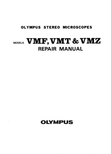
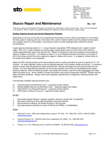
External Controls and FunctionsMain pulleyOutput shaftOutput shaftInversion/VariationcontrolBypass leverBrake leverSwitch3
Product identification-The product identification number is located on the top of the bar-code stickerand engraved on the left output shaft.SafetyPersonal SafetyTool SafetySafety precautions must be observedwhile servicing or repairing thetransmission. This section is to be used inconjunction with all other safety materialwhich may apply, such as:-Local and shop safety rules.-Government safety laws andregulations.Use the proper tools and equipmentfor the tasks.Servicing SafetyCertain procedures may require thevehicle to be disabled.Do not place speed above safety.Wear appropriate clothing. Loose orhanging clothing can be hazardous. Usethe appropriate safety equipment.4
General InstructionsPreliminary checks before tearing down the transmission- Clean up the transmission- Check all the controls between tractor and transmission (see owner manual)- Check the belt routing- In case of failures in cold conditions, check the transmission functionality aftera while in a dry place. The failure might come from a frozen control system.- Check the correct installation of the transmission (see view below)Screwing torque: 13 3 Nm(9.5 2 lb-ft)Preliminary checks before re-installing the transmission- Ensure that the variation belt is in the correct position.5
- Make sure that the inversion rod is properly seated in the inversion lever, and has its 2springs.Inversion leverSprings- Verify the presence of the 3 springs.- Ensure that both variation levers are in the correct position.6
TroubleshootingTroubleshooting checklistCustomercomplaintsloss oftraction:‘no drive’loss ofinversionfunction:‘tractorwon’t gointoreverse/forward’trouble toinverse:‘hard shift’PotentialItem to replacefailureGround drive Ground Drivebelt tensionbeltReconnect thePedal linkagerod to thedisconnectedtransmissionbroken driverDriver KitshaftbrokendrivenDriven Kitvariatorbrokencontrol cambrokenguidance rod Control Kitbrokencontrol rodsaxlebrokenvariationleverVariation Kitbrokenvariation rodloss ofHardware kitvariation cliploss ofcontrol rods Hardware kitclipvariator beltVariator erinversion Kitdisconnectedbrokeninversion rodInversion Kitbrokeninversion rodspringbrokeninversionControl Kitlever 2Debris underClean DriverDrivervariatorvariatorBrokenDriverDriver KitvariatorWhite leverout ofControl Kitpositionstop plateClean cam andstuck on thestop platecontrol caminversionInversionsecuritysecurity . 10OP1DriverPNp. 11OP2Drivenp. 12OP3ISSSp. 13OP4Coverp. 14OP5Variationp. 15OP6Brakep. 16OP7Controlp. 17OP8Bypassp. 18OP9Inversionp. XPPGT79186PRR Replacement operationPPRR/P Preliminary operation7
TroubleshootingTroubleshooting checklistPotentialItem tofailurereplaceDebris underClean DriverDrivervariatorvariatorTractor notPedal notVerify thatstopping inreturning to the pedal isneutralneutralfreepositionBrokenDriverDriver KitvariatorPedal linkagecheck andpulling thefree thebrake leverbrake leverin neutralLoss ofcontrol camrollingresistance not returning Control Kitin neutral to neutralposition broken brakespringBrake Kitbroken brakelevercheck thePedallinkage tolinkagethe brakedisconnectedleverLoss ofbrakebrokenfunctionaluminumBrake Kitbrake leverInternalTransmissionfailurebrokendrivenDriven Kitvariatorspringdriver shaftlowerDriver KitbearingLoss offailurespeed rangeloose nut onRetightencontrol /nutsvariation rodMisadjustmentAdjust speedof the speed(screw)brokenneutralVariation Kitspringbrokentrouble toneutralreturn topositionthe neutralspringpositionControl Kitbrokenneutralpositionlevercan'tdisable thebrokenbypass withbypass springthe brakepedalbypass Kitbroken brakeleverbrokenloss ofbypass leverbypassclean andfunctionPedal notfree thereturning topedal toneutralreturn toneutralCustomercomplaintsPNGT79452p. 10OP1Driverp. 11OP2Drivenp. 12OP3ISSSp. 12OP4Coverp. 13OP5Variationp. 14OP6Brakep. 15OP7Controlp. 18OP8Bypassp. 19OP9InversionPp. 9452RGT79256XGT79453RRGT79256RGT79257xR Replacement operation/P Preliminary operation8
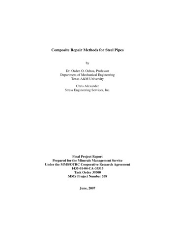
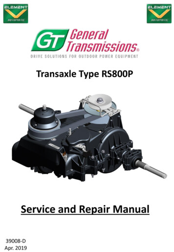
Transmission Tear Down-Remove cutting deck (see owner manual)Lift up the rear of the tractor, then remove both rear wheels.Disconnect the variation rod (1).Disconnect the switch (4).Disconnect the bypass rod (2).Disconnect the brake spring (3).Activate and lock the parking brake, to slacken the belt , and remove it from the mainpulley (5).Remove the mounting bolts, to separate the transmission from the frame.We recommend to keep 2 bolts partially unscrewed, to prevent the transmissionfrom falling.Lower the rear of the tractor until the transmission lightly touches the ground, thenremove the 2 last bolts.Lift up the rear of the tractor to release the transmission.512349
Repair ProceduresOP 1. Driver kit replacement (view p.24)- In case of speed down, the adjusting nut located on the variation rod allows to slightly increasethe speed.- Use a 10mm wrench.- Note: Over-adjustment of this screw can lead to thetractor creeping in Neutral! If this occurs, simply backout the screw until neutral is re-established.-Remove the 4 screws as shown below to liberate the driver kit, then the 2 screws to release thedebris shield.-At reassembly of the kit, make sure that:Both variation levers are properly seated.The belt is in the pulley.Screwing torque: 3.2 0.1 Nm(2,4 0.1 lb-ft)Variation levers position10
Repair ProceduresOP 2. Driven kit replacement (view p.25)-Remove the 3 screws to liberate the cover, press the aluminum ramp to compress the springand liberate the pin, then remove the aluminum ramp, spring and mobile flangeScrewing torque:2.2 0.1 Nm(1.6 0.1 lb-ft)-Unscrew the nut using the special tool P/N 79252 (see p.19), then remove the fixed flange.Screwing torque: 53,5 2 lb-ftMake sure not to lose the 8balls under the flangeWhen re-installing the components:-Make sure the 8 balls are present under the flange.-Respect the torques of the nut and screws.-Make sure the belt is properly positioned in the pulley.-Ensure that the spring is between the mobile flange and the aluminum ramp.11
Repair ProceduresOP 3. Inversion security system replacement (view p.28)-Remove the inversion security system.Make sure not to lose theballs under the flangeOP 4. Remove the protection coverScrewing torque: 3.2 0.1 Nm(2.4 0.1 lb-ft)12
Repair ProceduresOP 5. Variation kit replacement (view p.26)-Remove the e-clip to liberate the variation rod.E-clipWhen re-assembling the components, make sure that:-Both variation levers are correctly seated on the upper case.-The variation rod is properly positioned.Correct positionInformationNeutral spring is no longer neededand is not available in any kitIncorrect positionVariation levers13
Repair ProceduresOP 6. Brake kit replacement (view p.27)-Disconnect the brake spring, then remove the screws, to liberate the aluminum lever.Screwing torque: 3.2 0.2 Nm(2.4 0.1 lb-ft)-As the aluminum leverhas a conical shape, itmight be hard to remove.When re-installing the components:-Verify the presence of the O-ring-Gap between both lever is normal.-Respect screwing torque.Once you connect the spring to the brake lever, make sure there is notension between the spring and the lever in neutral position.14
Repair ProceduresOP 7. Controls kit replacement (view p.29)-Remove the e-clip to liberate the neutral spring and the variation control.-Remove the M8 screw, the control cam and the inversion lever (white).-Remove the screw to liberate the 2nd inversion lever.-Remove both control and variation rods.-Remove the 2 screws to liberate the neutral position lever and its spring.E-clipVariationcontrolNeutral springControl camInformationNeutral spring is no longer neededand is not available in any kitVariation rodNeutral position leverControl rod15
Repair ProceduresOP 7. Controls kit replacementWhen re-installing the components:-Verify the position of the neutral position lever.-Insert the inversion rod in the inversion lever before putting it on the upper case.-Insert both control and variation rods on the upper case.Variation rodControl rodNeutral positionleverScrewing torque3.2 0.2 Nm(2.4 0.1 lb-ft)Inversion rod-The cam and the inversion lever must be installed at the same time.-This assembly must be positioned at the same time on the pivot cam, inversion pivot leverand rods (5 points at the same time).-Verify the position of the variation control and its spring.16
Repair ProceduresOP 7. Controls kit replacement-The neutral position lever must be maintained to properly positioned the cam.Stopping plateScrewing torque: 6 1Nm(4.4 .1 lb-ft)- Respect the tightening torque.-As the variation control has not been attached, the cam should rotate freely.-The stopping plate must be free in rotation on the control cam.-Verify the position of the variation control.Correct positionIncorrect position17
Repair ProceduresOP 8. Bypass kit replacement (view p.30)-Separate and hold the 2 strips of the lever, to release the two studs and allow the leverremoval.- Remove bypass lever and its spring.- Correct position of the bypass lever and spring.18
Repair ProceduresOP 9. Inversion kit replacement (View p.31)- The inversion kit is located in front of the transmission.Screwing torque: 3.2 0.2 Nm(2.4 0.1 lb-ft)-Remove the inversion lever- Remove the nut to release thesprings and rod.- When re-install the kit, respect the adjustment.19
Repair ProceduresOP 10. Driver Variator CleaningPlease clean this areaClean particularly in thoseareasCheck if theflange set canmove freely.20
Repair ProceduresOP 10. Driver Variator CleaningPut the bearing Ø (red) in thelevers hole (yellow)Place the belt between theflanges for the both pulleysMake sure that both variation leversare well seated on the housing21
Repair ProceduresOP 10. Driver Variator CleaningAdd loctite 454 on the 4 screws :Screwing torque: 3.2 0.1 Nm(2,4 0.1 lb-ft)When you turn the pulley,the belt should not move.22
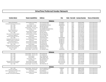
Exploded ViewItem123456789101112131423GT 2DesignationAnti-debris kit (including shield)BeltSecondary pulleyInversion Security SystemCoverControl kitRotating camVariation kitBrake kitBypass kitSealsInversion kitHardware kitDriven toolGT79252-Special tool is necessary to removethe Secondary pulleyGT79253.-Refer to the troubleshooting page7, to know when Secondary pulleymust be removed.
Anti-debris kitGT7945224
Secondary pulleyGT7925325
Variation KitGT7945326
Brake KitGT7925527
Inversion security setGT7918628
Exploded Controls KitGT79256Rotating camGT3801229
Exploded Bypass KitGT7925730
Exploded Inversion KitGT7925831
Hardware kitGT793231 bypass spring1 Neutral position spring1 brake spring3 screws 4x16 P/N:436212 washers P/N:426198 screws 5x16 P/N:43622CoverGT38800322 e-clips P/N:423212 screws 4x16 P/N:42623
Notes 33
General TransmissionsGeneral Transmissions inc.BP 317 – ZI du Bois Joly Sud2, Rue Johannes Gutemberg85503 Les Herbiers CedexFrance27351 Spectrum WayOak Ridge North, TX 77385USAGeneral Transmissions ChinaGeneral Transmissions de MexicoGeneral Transmissions (Suzhou)82 Ping Sheng Lu, SIPSuzhou, 215126P.R.ChinaAve. Uniones 90 - Zona IndustrialMatamoros, Tam. CP 87325MexicoAfter Sales Service transmissions.com
- Remove the mounting bolts, to separate the transmission from the frame. We recommend to keep 2 bolts partially unscrewed, to prevent the transmission from falling. - Lower the rear of the tractor until the transmission lightly touches the ground, then remove the 2 last bolts. - Lift up the rear of the tractor to release the transmission. 9 1 .