Transcription
Wire Ampacity andCalculations according tothe NECCopyright 1999-2020 Dan Dudley
Ampacity.The MAXIMUMCurrent in amperes, that a conductorcan carry continuously under theconditions of use without exceeding itstemperature ratingCopyright 1999-2020 Dan Dudley
310.15(A)(3) Temp. Limitations of ConductorsNo conductor shall be used in such amanner that its operating temperature willexceed that designated for the type ofinsulated conductor involved.FPN talks about ‘Serious Degradation’.Copyright 1999-2020 Dan Dudley
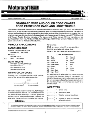
Insulation isHard,brown, andbrittleCopyright 1999-2020 Dan Dudley
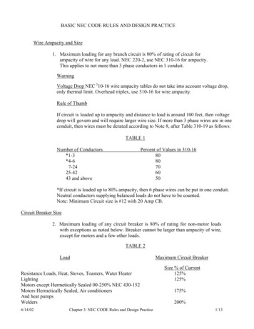
Romex – NM, NMC, NMS90º forDERATINGCopyright 1999-2020 Dan Dudley
NEC 2014 Article 110.14(C) Temperature Limitations. The temperaturerating associated with the ampacity of a conductor shallbe selected and coordinated so as not to exceed thelowest temperature rating of any connected termination,conductor, or device. Conductors with temperatureratings higher than specified for terminations shall bepermitted to be used for ampacity adjustment,correction, or both.Copyright 1999-2020 Dan Dudley
NEC 2014 Article 110.14(1) Equipment Provisions. The determination of termination provisions of equipment shall be based on110.14(C)(1) (a) or (C)(1)(b). Unless the equipment is listed and marked otherwise, conductor ampacities usedin determining equipmenttermination provisions shall be based on Table 310.15(B)(16) as appropriately modified by 310.15(B)(7).(a) Termination provisions of equipment for circuits rated 100 amperes or less, or marked for 14 AWGthrough 1 AWG conductors, shall be used only for one of the following:(1) Conductors rated 60 C (140 F).(2) Conductors with higher temperature ratings, provided the ampacity of such conductors is determined basedon the 60 C (140 F) ampacity of the conductor size used.(3) Conductors with higher temperature ratings if the equipment is listed and identified for use with suchconductors.(4) For motors marked with design letters B, C, or D, conductors having an insulation rating of 75 C (167 F) orhigher shall be permitted to be used, provided the ampacityof such conductors does not exceed the 75 C (167 F) ampacity.Copyright 1999-2020 Dan Dudley
NEC 2014 Article 110.14(b) Termination provisions of equipment for circuits rated over 100 amperes,or marked for conductors larger than 1 AWG, shall be used only for one of thefollowing:(1) Conductors rated 75 C (167 F)(2) Conductors with higher temperature ratings, provided the ampacity of suchconductors does not exceed the 75 C (167 F) ampacity of the conductor sizeused, or up to their ampacity if the equipment is listed and identified for use withsuch conductorsCopyright 1999-2020 Dan Dudley
110.14 (c) (1), & (2) Temperature Limitations of Conductors– #14 thru #1 or 100 amps or less Shall use the ampacity from the 60 C Column– Larger than #1 or over 100 amps Shall use the ampacity from the 75 C Column– The 90 C ampacity can be used for corrections only. Ambient Temperature Number of ConductorsCopyright 1999-2020 Dan Dudley
Copyright 1999-2020 Dan Dudley
Copyright 1999-2020 Dan Dudley
6350Copyright 1999-2020 Dan Dudley
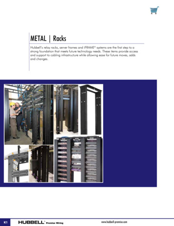
Table 310.15(B)(16) Parameters Not more than 3 current-carryingconductors Ambient temperature not exceeding 30 Centigrade or 86 FarenheightCopyright 1999-2020 Dan Dudley
T. 310.15(B)(16) Corrections Ambient Temperature– Above 30 C– Below 30 C Number of Conductors– More than 3 current carrying conductorsCopyright 1999-2020 Dan Dudley
Neutral Conductor Grounded Conductor– Carries unbalanced load– Is not counted if it only carries theunbalanced load.– Must be counted as a current carryingconductor if load consists of flourescentlighting or other harmonic loads.Copyright 1999-2020 Dan Dudley
Ampacity Calculations #1What is the Maximum allowed ampacity fora single #2 THHN Conductor installed in acircuit.Step 1. 110.14(c) (#14 thru #1)Step 2. Table 310.15(B)(16) (60 C Column)Step 3. Read Ampacity95 AmpsCopyright 1999-2020 Dan Dudley
Ampacity Calculations #2What is the Maximum allowed ampacity fora single #2 THHN Conductor not installed ina circuit.Step 1.Table 310.15(B)(16) (90 C Column)Step 3.Read Ampacity130 AmpsCopyright 1999-2020 Dan Dudley
Ampacity Calculations #3What is the Maximum allowed ampacity for asingle # 500 Kcmil THHN Conductor installedin a circuit with both 75 and 90 lugs.Step 1.110.14(c) (Larger than #1)Step 2.Table 310.15(B)(16) (75 C Column)Step 3.Read Ampacity380 AmpsCopyright 1999-2020 Dan Dudley
Copyright 1999-2020 Dan Dudley
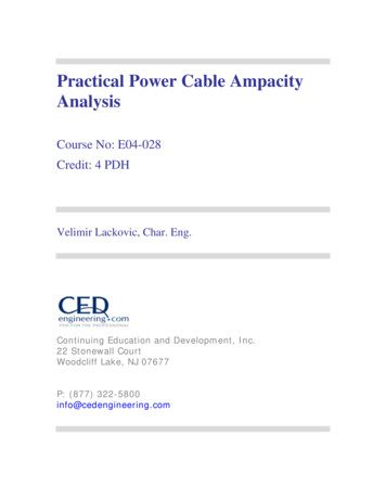
Adjustment FactorsCopyright 1999-2020 Dan Dudley
310.4in2020Copyright 1999-2020 Dan Dudley
310.4in2020Copyright 1999-2020 Dan Dudley
Ampacity Calculations #4What is the Maximum allowed ampacityfor a single # 500 Kcmil THHN Conductorin a 56 C environment and terminated ?Step 1. 110.14(c) (Larger than #1)Step 2. Table 310.15(B)(16) (90 C Column)Step 3. 430 Amps X .71 Correction Factor 305.3 AmpsStep 4. Look at 75 C column (Cannot exceed 380A)305 AmpsCopyright 1999-2020 Dan Dudley
Ampacity Calculations #5What is the Maximum allowed ampacity for asix # 4/0 Kcmil THW Conductors in a 143 Fenvironment ?Step 1. 110.14(c) (Larger than #1)Step 2. Table 310.15(B)(16) (75 C Column) (THW insulation)Step 3. 230 Amps X .47 (T) Step 4. 108.1 Amps X .80 (# Cond.) 108.1 Amps86.48 Amps86 AmpsCopyright 1999-2020 Dan Dudley
Ampacity Calculations #6What is the minimum size THHN conductor required forthe branch circuit conductors for a circuit of 120 volts,with a 10,000 watt load operating for 3.5 hours , locatedin a 68 C environment with 3 ungrounded conductors,1 grounded conductor, and 1 grounding conductor inconduit, connected to 75 C terminations and devices ?Existing load is fluorescent lightingCopyright 1999-2020 Dan Dudley
Keywords in questionWhat is the minimum size THHN conductor required forthe branch circuit conductors for a circuit of 120 volts,with a 10,000 watt load operating for 3.5 hours , locatedin a 68 C environment with 3 ungrounded conductors,1 grounded conductor, and 1 grounding conductor inconduit, connected to 75 C terminations and devices ?Existing load is fluorescent lightingCopyright 1999-2020 Dan Dudley
Solution to Question #6§Step 1: Get Current watts / volts 10,000/120 83.3 amps§Step 2: Continuous 125% 83.3 X 125% 104.125 Amps§ Definition of Continuous and Article 210.19§Step 3: Get Multiplier .80 X .58 .464§ T.310.15(b)(2)(a) .80 (4-6 conductors)§ T.310.15(B)(16) .58 (68 degrees C, 90 C Column)§Step 4: Get Wire Ampacity 104.125 / .464 224.407 amps§ Minimum Ampacity Required§Step 5: Select Wire (310.15(B)(16) & 110.14) #4/0 THHN (75 C)– Since all connections are stated at 75 degrees C#4/0 THHNCopyright 1999-2020 Dan Dudley
Ampacity Test Questions30 MinutesCopyright 1999-2020 Dan Dudley
NEC 2014 Article 110.14 (C) Temperature Limitations. The temperature rating associated with the ampacity of a conductor shall be selected and coordinated so as not to exceed the lowest temperature rating of any connected termination, conductor, or device. Conductors with temperature ratings higher than specified for terminations shall be